User Manual Installation Industrial Cellular Router - OWL LPWAN - UM Installation OWL LPWAN Release 02 02/2020 - Hirschmann ...
←
→
Page content transcription
If your browser does not render page correctly, please read the page content below
User Manual

Installation
Industrial Cellular Router
OWL LPWAN

UM Installation OWL LPWAN                      Technical support
Release 02 - 02/2020         https://hirschmann-support.belden.com
The naming of copyrighted trademarks in this manual, even when not specially indicated,
should not be taken to mean that these names may be considered as free in the sense of the
trademark and tradename protection law and hence that they may be freely used by anyone.

c 2020 Hirschmann Automation and Control GmbH

Manuals and software are protected by copyright. All rights reserved. The copying, repro-
duction, translation, conversion into any electronic medium or machine scannable form is not
permitted, either in whole or in part. An exception is the preparation of a backup copy of the
software for your own use.

The performance features described here are binding only if they have been expressly agreed
when the contract was made. This document was produced by Hirschmann Automation and
Control GmbH according to the best of the company’s knowledge. Hirschmann reserves the
right to change the contents of this document without prior notice. Hirschmann can give no
guarantee in respect of the correctness or accuracy of the information in this document.

Hirschmann can accept no responsibility for damages, resulting from the use of the network
components or the associated operating software. In addition, we refer to the conditions of use
specified in the license contract.

You can get the latest version of this manual on the Internet at the Hirschmann product site
(http://www.hirschmann.com).

Hirschmann Automation and Control GmbH
Stuttgarter Str. 45-51
72654 Neckartenzlingen
Germany

UM Installation OWL LPWAN                                                          2020-02-05
Contents
1 Safety Instructions                                                                                                                            8

2 FCC note                                                                                                                                      11

3 About this Manual                                                                                                                             12

4 Router Description                                                                                                                            13
   4.1 Usage of the Router . . . . . . . . . . . . . . . . . . . . . . . . . . . . . . . . . .                                                  14

5 Contents of Package                                                                                                                           17

6 Router Design                                                                                                                                 18
   6.1 Router Versions . . . . . . . . . . . . . . . . . . . . . .                  .   .   .   .   .   .   .   .   .   .   .   .   .   .   .   18
   6.2 Order Codes . . . . . . . . . . . . . . . . . . . . . . .                    .   .   .   .   .   .   .   .   .   .   .   .   .   .   .   19
   6.3 Basic Dimensions of the Router Box (specified in mm)                         .   .   .   .   .   .   .   .   .   .   .   .   .   .   .   20
   6.4 Mounting Recommendations . . . . . . . . . . . . . .                         .   .   .   .   .   .   .   .   .   .   .   .   .   .   .   21
   6.5 Removing from the DIN Rail . . . . . . . . . . . . . . .                     .   .   .   .   .   .   .   .   .   .   .   .   .   .   .   22
   6.6 Description of the Front Panel . . . . . . . . . . . . . .                   .   .   .   .   .   .   .   .   .   .   .   .   .   .   .   23
       6.6.1 Status Indication . . . . . . . . . . . . . . . . .                    .   .   .   .   .   .   .   .   .   .   .   .   .   .   .   24
       6.6.2 Power Connector PWR . . . . . . . . . . . . .                          .   .   .   .   .   .   .   .   .   .   .   .   .   .   .   25
       6.6.3 Ethernet Port ETH0 and ETH1 . . . . . . . . .                          .   .   .   .   .   .   .   .   .   .   .   .   .   .   .   26
       6.6.4 Antenna Connector ANT . . . . . . . . . . . . .                        .   .   .   .   .   .   .   .   .   .   .   .   .   .   .   27
       6.6.5 Reset Button . . . . . . . . . . . . . . . . . . .                     .   .   .   .   .   .   .   .   .   .   .   .   .   .   .   28
   6.7 Description of the Left Panel . . . . . . . . . . . . . . .                  .   .   .   .   .   .   .   .   .   .   .   .   .   .   .   30
       6.7.1 SIM Card Reader . . . . . . . . . . . . . . . . .                      .   .   .   .   .   .   .   .   .   .   .   .   .   .   .   31
       6.7.2 Serial Interfaces and I/O Port . . . . . . . . . .                     .   .   .   .   .   .   .   .   .   .   .   .   .   .   .   32

7 First Use                                                                                                                                     34
   7.1 Connecting the Router Before First Use . .           .   .   .   .   .   .   .   .   .   .   .   .   .   .   .   .   .   .   .   .   .   34
   7.2 Start . . . . . . . . . . . . . . . . . . . . . .    .   .   .   .   .   .   .   .   .   .   .   .   .   .   .   .   .   .   .   .   .   34
   7.3 Configuration . . . . . . . . . . . . . . . . .      .   .   .   .   .   .   .   .   .   .   .   .   .   .   .   .   .   .   .   .   .   34
       7.3.1 Configuration using a Web Browser              .   .   .   .   .   .   .   .   .   .   .   .   .   .   .   .   .   .   .   .   .   34

8 Maintenance and Service                                                                                                                       36

9 Technical Parameters                                                                                                                          37
   9.1   Basic Parameters . . . . . . . . . . . . . .   .   .   .   .   .   .   .   .   .   .   .   .   .   .   .   .   .   .   .   .   .   .   37
   9.2   Standards and Regulations . . . . . . . .      .   .   .   .   .   .   .   .   .   .   .   .   .   .   .   .   .   .   .   .   .   .   38
   9.3   Type Tests and Environmental Conditions        .   .   .   .   .   .   .   .   .   .   .   .   .   .   .   .   .   .   .   .   .   .   39
   9.4   Technical Parameters of Cellular Module .      .   .   .   .   .   .   .   .   .   .   .   .   .   .   .   .   .   .   .   .   .   .   40
   9.5   Other Technical Parameters . . . . . . . .     .   .   .   .   .   .   .   .   .   .   .   .   .   .   .   .   .   .   .   .   .   .   41

10 Related Documents                                                                                                                            42

UM Installation OWL LPWAN
Release 02 - 02/2020                                                                                                                             3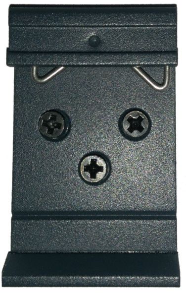
11 Further Support                            43

                     UM Installation OWL LPWAN
4                            Release 02 - 02/2020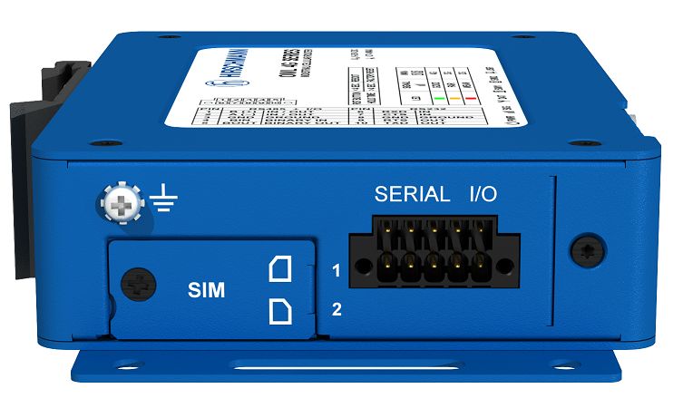
List of Figures
   1    Access to the Internet from LAN . . . . .        .   .   .   .   .   .   .   .   .   .   .   .   .   .   .   .   .   .   .   .   .   .   14
   2    Backed up access to the Internet . . . . .       .   .   .   .   .   .   .   .   .   .   .   .   .   .   .   .   .   .   .   .   .   .   15
   3    Using VPN tunnel . . . . . . . . . . . . .       .   .   .   .   .   .   .   .   .   .   .   .   .   .   .   .   .   .   .   .   .   .   15
   4    Serial Gateway . . . . . . . . . . . . . . .     .   .   .   .   .   .   .   .   .   .   .   .   .   .   .   .   .   .   .   .   .   .   16
   5    OWL LPWAN . . . . . . . . . . . . . . . .        .   .   .   .   .   .   .   .   .   .   .   .   .   .   .   .   .   .   .   .   .   .   18
   6    Basic dimensions of the router box . . . .       .   .   .   .   .   .   .   .   .   .   .   .   .   .   .   .   .   .   .   .   .   .   20
   7    Basic dimensions of the router box . . . .       .   .   .   .   .   .   .   .   .   .   .   .   .   .   .   .   .   .   .   .   .   .   20
   8    Default position of DIN rail clip . . . . . .    .   .   .   .   .   .   .   .   .   .   .   .   .   .   .   .   .   .   .   .   .   .   22
   9    Removing from the DIN rail . . . . . . . .       .   .   .   .   .   .   .   .   .   .   .   .   .   .   .   .   .   .   .   .   .   .   22
   10   The front panel of the router . . . . . . . .    .   .   .   .   .   .   .   .   .   .   .   .   .   .   .   .   .   .   .   .   .   .   23
   11   Power connector . . . . . . . . . . . . . .      .   .   .   .   .   .   .   .   .   .   .   .   .   .   .   .   .   .   .   .   .   .   25
   12   Connection of power supply . . . . . . . .       .   .   .   .   .   .   .   .   .   .   .   .   .   .   .   .   .   .   .   .   .   .   25
   13   Ethernet connector . . . . . . . . . . . . .     .   .   .   .   .   .   .   .   .   .   .   .   .   .   .   .   .   .   .   .   .   .   26
   14   Connection of Ethernet cables . . . . . .        .   .   .   .   .   .   .   .   .   .   .   .   .   .   .   .   .   .   .   .   .   .   26
   15   Connecting the antenna . . . . . . . . . .       .   .   .   .   .   .   .   .   .   .   .   .   .   .   .   .   .   .   .   .   .   .   27
   16   Router reset . . . . . . . . . . . . . . . . .   .   .   .   .   .   .   .   .   .   .   .   .   .   .   .   .   .   .   .   .   .   .   28
   17   The left panel of the router . . . . . . . . .   .   .   .   .   .   .   .   .   .   .   .   .   .   .   .   .   .   .   .   .   .   .   30
   18   SIM card reader . . . . . . . . . . . . . .      .   .   .   .   .   .   .   .   .   .   .   .   .   .   .   .   .   .   .   .   .   .   31
   19   Serial + I/O connector . . . . . . . . . . .     .   .   .   .   .   .   .   .   .   .   .   .   .   .   .   .   .   .   .   .   .   .   32
   20   Functional scheme of the binary interface        .   .   .   .   .   .   .   .   .   .   .   .   .   .   .   .   .   .   .   .   .   .   33

UM Installation OWL LPWAN
Release 02 - 02/2020                                                                                                                              5
List of Tables
    1    Contents of package . . . . . . . . . . .     .   .   .   .   .   .   .   .   .   .   .   .   .   .   .   .   .   .   .   .   .   .   .   17
    2    Router versions . . . . . . . . . . . . . .   .   .   .   .   .   .   .   .   .   .   .   .   .   .   .   .   .   .   .   .   .   .   .   18
    3    Order Codes Overview . . . . . . . . . .      .   .   .   .   .   .   .   .   .   .   .   .   .   .   .   .   .   .   .   .   .   .   .   19
    4    Description of the front panel . . . . . .    .   .   .   .   .   .   .   .   .   .   .   .   .   .   .   .   .   .   .   .   .   .   .   23
    5    Status indication . . . . . . . . . . . . .   .   .   .   .   .   .   .   .   .   .   .   .   .   .   .   .   .   .   .   .   .   .   .   24
    6    Connection of power connector . . . . .       .   .   .   .   .   .   .   .   .   .   .   .   .   .   .   .   .   .   .   .   .   .   .   25
    7    Connection of Ethernet connector . . . .      .   .   .   .   .   .   .   .   .   .   .   .   .   .   .   .   .   .   .   .   .   .   .   26
    8    Overview of router reboot and reset . . .     .   .   .   .   .   .   .   .   .   .   .   .   .   .   .   .   .   .   .   .   .   .   .   29
    9    Description of the left panel . . . . . . .   .   .   .   .   .   .   .   .   .   .   .   .   .   .   .   .   .   .   .   .   .   .   .   30
    10   Connection of RS485 . . . . . . . . . .       .   .   .   .   .   .   .   .   .   .   .   .   .   .   .   .   .   .   .   .   .   .   .   32
    11   Connection of I/O . . . . . . . . . . . . .   .   .   .   .   .   .   .   .   .   .   .   .   .   .   .   .   .   .   .   .   .   .   .   32
    12   Connection of RS232 . . . . . . . . . .       .   .   .   .   .   .   .   .   .   .   .   .   .   .   .   .   .   .   .   .   .   .   .   32
    13   Basic parameters . . . . . . . . . . . . .    .   .   .   .   .   .   .   .   .   .   .   .   .   .   .   .   .   .   .   .   .   .   .   37
    14   Standards and regulations . . . . . . . .     .   .   .   .   .   .   .   .   .   .   .   .   .   .   .   .   .   .   .   .   .   .   .   38
    15   Type tests and environmental conditions       .   .   .   .   .   .   .   .   .   .   .   .   .   .   .   .   .   .   .   .   .   .   .   39
    16   Technical parameters of cellular module       .   .   .   .   .   .   .   .   .   .   .   .   .   .   .   .   .   .   .   .   .   .   .   40
    17   Other technical parameters . . . . . . .      .   .   .   .   .   .   .   .   .   .   .   .   .   .   .   .   .   .   .   .   .   .   .   41

                                                                                       UM Installation OWL LPWAN
6                                                                                                              Release 02 - 02/2020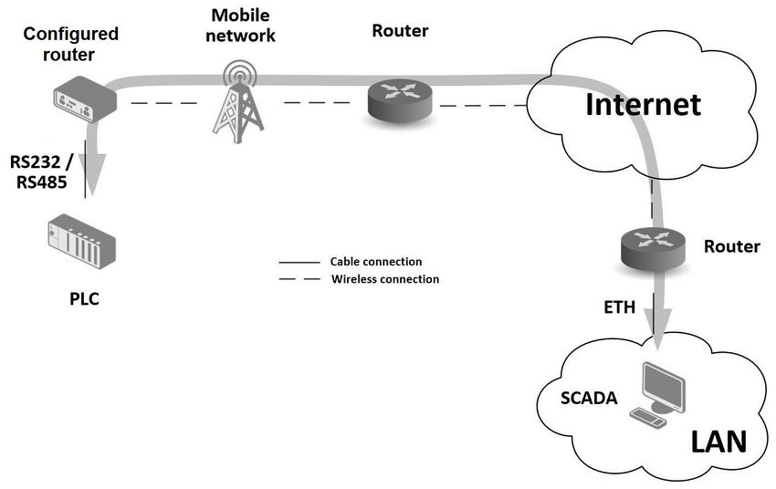
Used Symbols
      Danger – Information regarding user safety.

      Note – Problems that can arise in specific situations.

      Information – Useful tips or information of special interest.

      Example – Example of function, command or script.

UM Installation OWL LPWAN
Release 02 - 02/2020                                                  7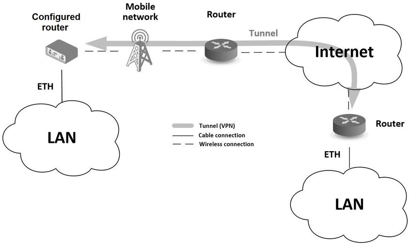
1 Safety Instructions

                                           WARNING
    UNCONTROLLED MACHINE ACTIONS
    To avoid uncontrolled machine actions caused by data loss, configure all the data transmis-
    sion devices individually.
    Before you start any machine which is controlled via data transmission, be sure to complete
    the configuration of all the data transmission devices.

    Failure to follow these instructions can result in death, serious injury, or equipment
    damage.

     • General safety instructions
        You operate this device with electricity. Improper usage of the device entails the risk
        of physical injury or significant property damage. The proper and safe operation of this
        device depends on proper handling during transportation, proper storage and installation,
        and careful operation and maintenance procedures.
          X Before connecting any cable, read this document, and the safety instructions and
            warnings.
          X Operate the device with undamaged components exclusively.
          X The device is free of any service components. In case of a damaged or malfunc-
            tioning device, turn off the supply voltage and return the device to Hirschmann for
            inspection.
          X Only routers with appropriate certification and labelling should be used in locations
            where flammable and explosive materials are present, including gas stations, chem-
            ical plants, or locations in which explosives are used. We remind users of the duty
            to observe the restrictions concerning the utilization of radio devices at such places.
          X Switch off the router when travelling by plane. Utilization of the router on a plane
            may endanger the operation of the plane or interfere with the mobile telephone net-
            work, and may be unlawful. Failure to observe these instructions may result in the
            suspension or cancellation of telephone services for the respective client and/or may
            result in legal sanctions.

     • Certified usage
          X Use the product only for the application cases described in the Hirschmann product
            information, including this manual.
          X Operate the product only according to the technical specifications. See "Technical
            Parameters".
          X Connect to the product only components suitable for the requirements of the specific
            application case.

                                                                    UM Installation OWL LPWAN
8                                                                             Release 02 - 02/2020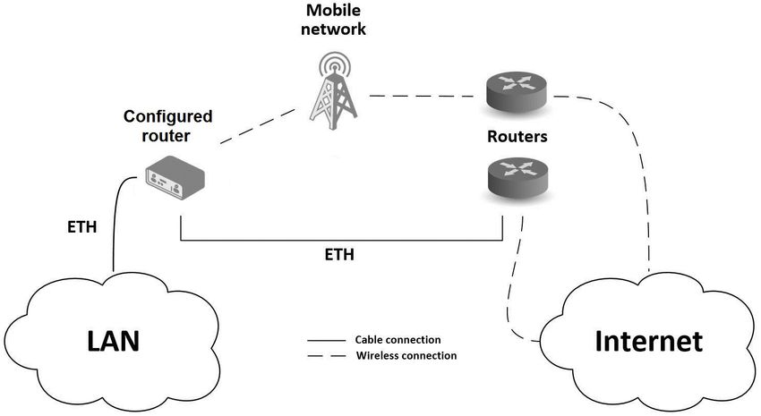
• Installation site requirements
       X When you are selecting the installation location, make sure you observe the climatic
         threshold values specified in the technical data.
       X Operate the device at the specified ambient temperature (temperature of the ambient
         air at a distance of 2 in (5 cm)).
       X Use the device in an environment with a maximum pollution degree that complies
         with the specifications in the technical data.
       X Turn off the router and disconnect it from power supply before handling the SIM card.
       X Caution! The SIM card could be swallowed by small children.
       X Power supply must not exceed 60 V DC max.
       X When using the router in close proximity to personal medical devices, such as car-
         diac pacemakers or hearing aids, you must proceed with heightened caution.
       X The router may cause interference when used in close proximity to TV sets, radio
         receivers or personal computers.

   • Device casing
     Only technicians authorized by the manufacturer are permitted to open the casing.
       X Never insert sharp objects (narrow screwdrivers, wires, etc.) into the contacts for
         electric conductors and do not touch the contacts.

   • Qualification requirements for personnel
       X Only allow qualified personnel to work on the device.
     Qualified personnel have the following characteristics:
       X Qualified personnel are properly trained. Training as well as practical knowledge
         and experience make up their qualifications. This is the prerequisite for grounding
         and labeling circuits, devices, and systems in accordance with current standards in
         safety technology.
       X Qualified personnel are aware of the dangers that exist in their work.
       X Qualified personnel are familiar with appropriate measures against these hazards in
         order to reduce the risk for themselves and others.
       X Qualified personnel receive training on a regular basis.

   • National and international safety regulations
       X Verify that the electrical installation meets local or nationally applicable safety regu-
         lations.
       X When installing antennas, observe the regulations of the country in which you are
         operating the WLAN device with regard to the general operating permission and the
         maximum emission levels.
       X Install and operate this equipment with a minimum distance of 7.9 in (20 cm) between
         the antenna and your body.

   • Recycling note
     After usage, this device must be disposed of properly as electronic waste, in accordance
     with the current disposal regulations of your county, state, and country.

UM Installation OWL LPWAN
Release 02 - 02/2020                                                                            9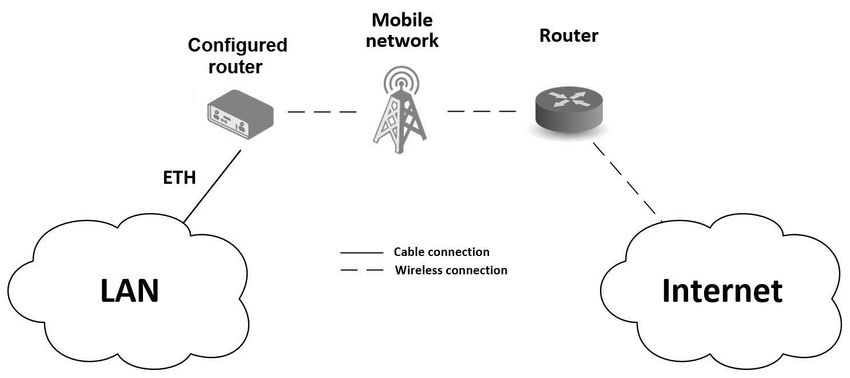
• Grounding the device
       The device is grounded via the grounding screw.
        X Shielding ground
          The shielding ground of the connectable twisted pair cable is connected to the
          grounding connector as a conductor.
        X Beware of possible short circuits when connecting a cable section with conductive
          shielding braiding.

     • Data backup
        X It is recommended that you create an appropriate copy or backup of all important
          settings that are stored in the memory of the device.

                                                              UM Installation OWL LPWAN
10                                                                      Release 02 - 02/2020
2 FCC note
Supplier’s Declaration of Conformity
47 CFR § 2.1077 Compliance Information
OWL 4G LPWAN
U.S. Contact Information
Belden – St. Louis
1 N. Brentwood Blvd. 15th Floor
St. Louis, Missouri 63105, United States
Phone: 314.854.8000
This device complies with part 15 of the FCC rules.
Operation is subject to the following two conditions:
• This device may not cause harmful interference, and
• This device must accept any interference received, including interference that may cause
undesired operation.
This equipment has been tested and found to comply with the limits for a Class B digital
device, pursuant to part 15 of the FCC Rules. These limits are designed to provide reasonable
protection against harmful interference in a residential installation. This equipment generates,
uses and can radiate radio frequency energy and, if not installed and used in accordance with
the instructions, may cause harmful interference to radio communications. However, there is
no guarantee that interference will not occur in a particular installation. If this equipment does
cause harmful interference to radio or television reception, which can be determined by turning
the equipment off and on, the user is encouraged to try to correct the interference by one or
more of the following measures:
• Reposition the receiver antenna or change the angle of the receiver antenna.
• Increase the separation between the device and the receiver.
• Connect the device to a different outlet on a different power supply cable from that to
which the receiver is connected.
• Consult a specialist retailer or an electronic systems engineer for help.
Changes or modifications not expressly approved by the holder of the certificate could void
the user’s authority to operate this equipment.
Contains Transmitter Module
FCC ID: XMR201808EC25AF
IC ID: 10224A-2018EC25AF
UM Installation OWL LPWAN
Release 02 - 02/2020 113 About this Manual
The "Instalation" user manual contains a device description, safety instructions, a description
of the display, and the other information that you need to install the device.
Documentation mentioned in the "User Manual Installation" that is not supplied with your
device as a printout can be found as PDF files for downloading on the Internet at:
https://www.doc.hirschmann.com/.
UM Installation OWL LPWAN
12 Release 02 - 02/20204 Router Description OWL LPWAN is an industrial cellular router intended for the North American market (NAM). This router is designed for wireless communication in the mobile networks that make use of traditional cellular technologies. The primary purpose of this router is its use in the Category M1 (Cat M1) services on the cellular LTE network. LTE Cat M1 is a new cellular technology specifically designed for the needs of applications targeting the Internet of Things (IoT) or machine-to-machine (M2M) communications. LTE Cat M1 is a low-power wide-area (LPWA) air interface that lets you connect IoT and M2M devices with medium data rate requirements (375 kbps upload and download speeds in half duplex mode). The standard configuration includes two Ethernet 10/100 ports, serial line RS232, RS485, one binary input and one output. The device also has two readers for 3 V and 1.8 V SIM cards, which are located on the left panel of the router. The router can be provided only in a metal casing. The OWL LPWAN router is equipped with a power backup feature. It is a short-term power backup (maximum 15 seconds - depending on technology) which is used to complete the run- ning operation or to send the required data immediately after failure of power supply. Configuration of the router may be done via a password-protected Web interface. Web in- terface provides detailed statistics about the router’s activities, signal strength, detailed system log etc. The router supports the creation of VPN tunnels using IPSec, OpenVPN and L2TP to ensure safe communication. DHCP, NAT, NAT-T, DynDNS, NTP, VRRP, control by SMS, backup primary connection and many other functions are supported. The router provides diagnostic functions which include automatically monitoring the PPP connection, automatic restart in case of connection losses, and a hardware watchdog that monitors the router status. The user may insert Linux scripts which are started on various actions. It is possible to create up to four different configurations for the same router. These configurations can be switched whenever necessary via Web interface, SMS or binary input status. The router can automatically upgrade its configuration and firmware from your central server. This allows for mass reconfiguration of numerous routers at the same time. UM Installation OWL LPWAN Release 02 - 02/2020 13
Examples of possible applications

       •   mobile office                            • telemetric
       •   fleet management                         • remote monitoring
       •   security system                          • vending and dispatcher machines
       •   telematic

4.1 Usage of the Router
  The router is primarily intended for these four basic situations:

     I. Access to the Internet from LAN

                              Figure 1: Access to the Internet from LAN

                                                                      UM Installation OWL LPWAN
14                                                                            Release 02 - 02/2020
II. Backed up access to the Internet (from LAN)
Figure 2: Backed up access to the Internet
III. Secure networks interconnection or using VPN
Figure 3: Using VPN tunnel
UM Installation OWL LPWAN
Release 02 - 02/2020 15IV. Serial Gateway
Figure 4: Serial Gateway
UM Installation OWL LPWAN
16 Release 02 - 02/20205 Contents of Package
The standard set of router includes items listed in following table:
Item# Description Figure Q’ty
1 Router 1 pcs
DIN holder
2 1 pcs
(screwed on the router)
Wing on wall mounting
3 2 pcs
(screwed on the router)
2-pin terminal block for power supply
4 1 pcs
(deployed on the router)
10-pin terminal block for RS232,
5 RS485 and I/O 1 pcs
(deployed on the router)
6 Printed "General Safety Instructions" 1 pcs
Printed "Open Source Information
7 1 pcs
OWL Family"
Table 1: Contents of package
UM Installation OWL LPWAN
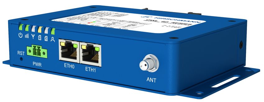
Release 02 - 02/2020 176 Router Design
6.1 Router Versions
OWL LPWAN router is supplied in the following versions (see table below). All versions are
available in a metal box.
RS232
RS485
BOUT
ETH
SIM
BIN
Router versions
OWL LPWAN 2x 1x 1x 2x 1x 1x
Table 2: Router versions
Figure 5: OWL LPWAN
UM Installation OWL LPWAN
18 Release 02 - 02/20206.2 Order Codes
Order codes overview is shown in the table below.
Product type Product name Order code Features – interfaces
OWL 4G OWL LPWAN 942 286-001 LTE module for NAM, 2x ETH, 1x BI, 1x BO,
1x RS232, 1x RS485, 2x SIM reader
Table 3: Order Codes Overview
UM Installation OWL LPWAN
Release 02 - 02/2020 196.3 Basic Dimensions of the Router Box (specified in mm)
Figure 6: Basic dimensions of the router box
Figure 7: Basic dimensions of the router box
UM Installation OWL LPWAN
20 Release 02 - 02/20206.4 Mounting Recommendations Router can be placed: • on a flat surface, • on a wall (or other surface) using the side wings, • on a DIN rail EN 60715 with the included metal DIN rail clip. If the negative pole of the router is grounded, there is no protection against reversed polarity! The only protection left is the fuse inside the device. Only the service center can restore the router’s functionality. UM Installation OWL LPWAN Release 02 - 02/2020 21
6.5 Removing from the DIN Rail
The DIN rail clip is suitable for a DIN rail according to EN 60715 standard only. The default
position of metal rail clip, which is used for mounting the router on a DIN rail, is shown in the
following figure. Its position can be changed on some models (back or bottom). When changing
the position of the DIN rail clip, tighten the screws with max. 0.4 Nm torque.
Figure 8: Default position of DIN rail clip
To remove the router from the DIN rail it is necessary to lightly push down the router so that
the bottom part of the DIN rail clip hitched to the DIN rail get out of this rail and then fold out the
bottom part of the router away from the DIN rail.
Figure 9: Removing from the DIN rail
UM Installation OWL LPWAN
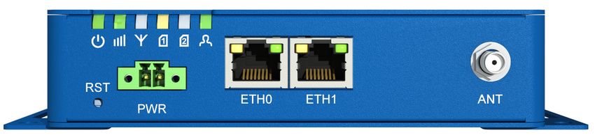
22 Release 02 - 02/20206.6 Description of the Front Panel
On the front panel of the router, there are located:
Caption Connector Description
RST — RST button used to restore the default configuration and re-
boot the router
PWR 2-pin Terminal block for the power supply
ETH0 RJ45 Ethernet connection to the computer network
ETH1 RJ45 Ethernet connection to the computer network
ANT SMA Connector for main antenna
Table 4: Description of the front panel
Figure 10: The front panel of the router
UM Installation OWL LPWAN
Release 02 - 02/2020 236.6.1 Status Indication
There are six LED indicators on the front panel to provide router status information. Each
ETH port has two additional LEDs that provide information about the port status.
Caption Color State Description
PWR Green On Starting of the router
Green Blinking Router is ready
Green Fast blinking Updating firmware
SIG Green On Good signal
Orange On Fair signal
Red On Poor signal
DAT Green Blinking Communication in progress on radio channel
SIM1 Green Blinking SIM is selected, router waits for data connection
Green On 4G technology
Red On 2G technology
Red Fast blinking SIM card problem (missing SIM card or PIN code not
entered)
SIM2 Green Blinking SIM is selected, router waits for data connection
Green On 4G technology
Red On 2G technology
Red Fast blinking SIM card problem (missing SIM card or PIN code not
entered)
USR Green On / Blinking / Function of this LED diode can be selected by user
Fast blinking
ETH0 Green On Selected 100 Mbps
ETH1 Green Off Selected 10 Mbps
ETH0 Yellow On The network cable is connected
ETH1 Yellow Blinking Data transmission
Yellow Off The network cable is not connected
Table 5: Status indication
UM Installation OWL LPWAN
24 Release 02 - 02/20206.6.2 Power Connector PWR
Terminal block 3.5 mm.
Pin number Signal mark Description
1 VCC(+) Positive pole of DC supply voltage (+9 to +36 V DC)
2 GND(-) Negative pole of DC supply voltage
Table 6: Connection of power connector
Figure 11: Power connector
Power supply for router is required between +9 V to +36 V DC supply. Protection against
reversed polarity without signaling is built into the router.
If the negative pole of the router is grounded, there is no protection against reversed
polarity! The only protection left is the fuse inside the device. Only the service center can
restore the router’s functionality.
For correct operation it is necessary that the power source is able to supply a peak current
of 1.2 A.
Unit has to be supplied by a power supply specified as a Limited Power Source (LPS) or
CEC/NEC Class 2 source of supply.
In applications requiring low power consumption (such as solar power - not 7/24 mode) is
strictly recommended to use "LPM" mode prior to powering down the entire router.
Circuit example:
Figure 12: Connection of power supply
All metal parts, including the box, are connected together with the negative pole of power supply
(common pole). To ground the router can be used the grounding screw located on the left panel.
UM Installation OWL LPWAN
Release 02 - 02/2020 256.6.3 Ethernet Port ETH0 and ETH1
The panel socket of RJ45 is used for this interface. The insulation strength of Ethernet ports
from each other and from the rest of the router (grounding) is 1500 V.
Pin Signal mark Description Data flow direction
1 TXD+ Transmit Data – positive pole Input/Output
2 TXD- Transmit Data – negative pole Input/Output
3 RXD+ Receive Data – positive pole Input/Output
4 — —
5 — —
6 RXD- Receive Data – negative pole Input/Output
7 — —
8 — —
Table 7: Connection of Ethernet connector
Figure 13: Ethernet connector
The Ethernet cable plugs into the RJ45 connectors labeled as ETH0 and ETH1 (see the
figure below).
Figure 14: Connection of Ethernet cables
UM Installation OWL LPWAN
26 Release 02 - 02/20206.6.4 Antenna Connector ANT
The ANT connector is used to connect the main antenna to the router.
The router can not operate without a main antenna connected through the port marked as
ANT.
The SMA connector is used for the connection of the antenna. Recommended tightening mo-
ment for screwing the antenna to SMA connectors is 0.9 Nm.
Figure 15: Connecting the antenna
UM Installation OWL LPWAN
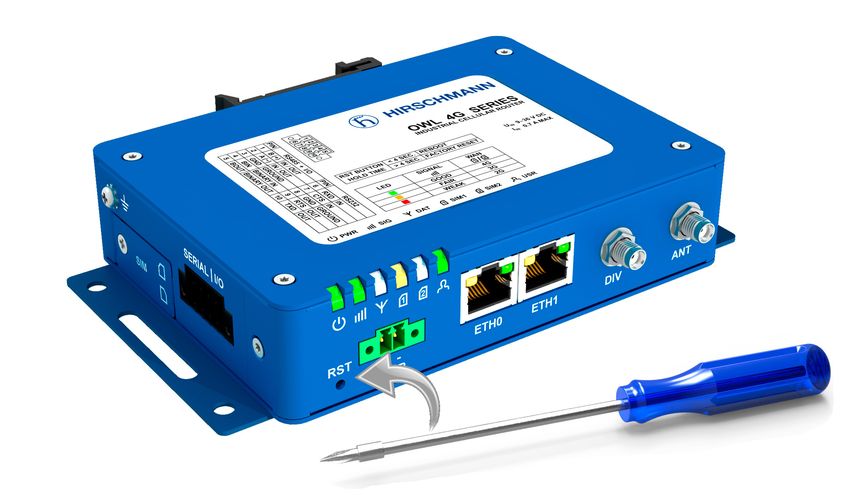
Release 02 - 02/2020 276.6.5 Reset Button
The RST button on the front panel has three functions on OWL 4G routers:
• Reboot the router:
Hold the RST button for less than 4 seconds, the router will be restarted.
• Factory reset – restore the default configuration:
Hold the RST button for more than 4 seconds. The PWR LED turns off and on again.
We recommend holding down the RST button for 1 second after turning on the PWR LED
on the front panel.
• Factory reset – restore the default configuration when unable to boot:
If the router is unable to boot due to a bad configuration, turn off the router (power
supply). Push and hold the RST button, turn on the router and hold the RST button for at
least 10 seconds. This will return the router to default configuration.
Before performing the factory reset of the router, it is recommended to back up the router
configuration settings (see "Configuration OWL 4G Family" user manual) because reset
of the router will return all configuration settings to their default states.
You can download the "Configuration OWL 4G Family" user manual on the Internet
at: https://www.doc.hirschmann.com/.
In order to press the RST button it is necessary to use a narrow screwdriver or any other small
tool.
Figure 16: Router reset
UM Installation OWL LPWAN
28 Release 02 - 02/2020Action Router behavior Trigger events – options
Reboot Turns off and then
turns on the router
• Disconnect and reconnect the power
• Send text reboot via SMS to SIM card number
put in your router (your phone number has to be
authorized – see the Configuration Manual for
OWL 4G routers)
• Press the Reboot menu item in the Web interface
• Press the RST button, hold less than 4 seconds
Reset Restores the default
(factory) configuration and
• Hold the RST button for more than 4 seconds
reboots the router
• If it does not help (router does not start at all),
turn off the router (power supply). Push and hold
the RST button, then turn on the router and hold
the RST button for more than 10 seconds.
Table 8: Overview of router reboot and reset
UM Installation OWL LPWAN
Release 02 - 02/2020 296.7 Description of the Left Panel
Interfaces located on the left panel are described in the table below.
Caption Connector Description
Grounding screw M3 screw Grounding screw (M3x6L) is connected to the ground of
the board and to the negative pole of the power source.
SIM cards 2FF size Unscrew the SIM cards cover to access the SIM1 and
SIM2 slots.
SERIAL | I/O 10-pin This connector has the RS232 and RS485 serial inter-
faces, one binary input and one binary output. The con-
nector pinout is printed on the top label.
Table 9: Description of the left panel
Figure 17: The left panel of the router
UM Installation OWL LPWAN
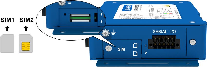
30 Release 02 - 02/20206.7.1 SIM Card Reader
Two SIM card readers for 3 V and 1.8 V SIM cards are located on the left panel of the
router. In order for the router to function, it is necessary to insert an activated SIM card with
an unblocked PIN code, or you can enter the PIN code in the router web interface. The SIM
cards may have different adjusted APNs (Access Point Names).
Type of SIM cards: Mini SIM (2FF) 25.0 x 15.0 x 0.76 mm.
Changing the SIM card:
• Always disconnect the router from power supply before handling the SIM card!
• Unscrew the SIM card cover.
• Using a plastic opening tool, or your fingernail, press the SIM card slightly into its
slot until you hear a click.
• After hearing this click, release the card and it will pop out of its slot.
• Remove the SIM card and push any other SIM card into the slot until it clicks into
place.
Figure 18: SIM card reader
For Verizon Wireless network, SMS messages will be transmitted successfully only if both
of the end devices are equipped with an LTE Cat-M cellular module.
UM Installation OWL LPWAN
Release 02 - 02/2020 316.7.2 Serial Interfaces and I/O Port
The RS232 and RS485 serial interfaces together with the I/O interface are physically con-
nected to the 10-pin panel socket. All three interfaces are not isolated from the router. The
pinout of this conector is described in the tables below.
Figure 19: Serial + I/O connector
Pin Signal mark Description
1 B (+) IN/OUT
2 A (-) IN/OUT
3 GND GROUND
Table 10: Connection of RS485
Pin Signal mark Description
4 BIN BINARY IN
5 BOUT BINARY OUT
Table 11: Connection of I/O
Pin Signal mark Description
6 RXD IN
7 CTS IN
8 GND GROUND
9 RTS OUT
10 TXD OUT
Table 12: Connection of RS232
The I/O user interface is designed for binary input processing and binary output control. By
default, the binary output is open, so it is not grounded. The maximum binary output load is
36 V at 500 mA. The constant current supplied by the binary input is 3 mA.
UM Installation OWL LPWAN
32 Release 02 - 02/2020The functional scheme of connection for the binary input and binary output is drawn on the
picture below.
Figure 20: Functional scheme of the binary interface
UM Installation OWL LPWAN
Release 02 - 02/2020 337 First Use
7.1 Connecting the Router Before First Use
Before putting the router into operation it is necessary to connect all of the components that
are required to run your applications. Don’t forget to insert a SIM card.
The router can not operate without a connected antenna, SIM card and power supply. If
the antenna is not connected, the router may be damaged.
Be very careful when tightening the antenna. If you over tighten the antenna, then you can
twist the antenna connector off of the circuit board.
7.2 Start
The router will start when a power supply is connected to the router. By default, the router will
automatically start to log on to the default APN. The DHCP server will start to assign addresses
for devices connected through the Ethernet port ETH0. Router’s behavior can be changed via
the web interface. This is described in detail in the "Configuration OWL 4G Family" user manual
that you can download at: https://www.doc.hirschmann.com/.
7.3 Configuration
If no SIM card is inserted in the router, it is not possible for the router to operate. Any
inserted SIM card must have active data transmission.
7.3.1 Configuration using a Web Browser
For status monitoring, configuration and administration of the router a web interface is avail-
able which can be accessed by entering the IP address of the router into the web browser. The
default IP address of the router is 192.168.1.1 netmask 255.255.255.0.
Use the HTTPS protocol to help maintain secure communication.
Applies to devices that are delivered without unique default password
• The default settings allow only the user “admin” with the default password “private” to
configure the router.
• After successfully entering the login information a user has access to the router using the
Internet browser.
UM Installation OWL LPWAN
34 Release 02 - 02/2020Applies to devices that are delivered with an unique default password that is located
on a label on the device
Perform the following steps:
1. Open the web interface the first time you log on to the device.
2. Type in the user name “admin”.
3. Type in the unique default password that is located on a label (“Def. password”) on the
device.
4. Click the “Login” button. After successfully entering the login information you have access
to the router using the Internet browser.
5. To help maintain the security of your network, change the unique default password
of the router.
Some features may be disabled until you change the unique default password.
The unique default password will be applied again if you reset the router by the “Reset” button.
You find a detailed description of the router settings in the Web interface in the "User Manual
Configuration OWL 4G Family".You can download the PDF on the Internet at: https://www.
doc.hirschmann.com/.
UM Installation OWL LPWAN
Release 02 - 02/2020 358 Maintenance and Service
• When designing this device, Hirschmann largely avoided using high-wear parts. The parts
subject to wear and tear are dimensioned to last longer than the lifetime of the product
when it is operated normally. Operate this device according to the specifications.
• Relays are subject to natural wear. This wear depends on the frequency of the switching
operations. Check the resistance of the closed relay contacts and the switching function
depending on the frequency of the switching operations.
• Hirschmann is continually working on improving and developing their software. Check
regularly whether there is an updated version of the software that provides you with addi-
tional benefits. You find information and software downloads on the Hirschmann product
pages on the Internet (https://hirschmann.com).
Note: You find information on settling complaints on the Internet at
http://www.beldensolutions.com/en/Service/Repairs/index.phtml.
UM Installation OWL LPWAN
36 Release 02 - 02/20209 Technical Parameters
9.1 Basic Parameters
Router parameters
Temperature range Operating -40 ◦ C to +65 ◦ C
Storage -40 ◦ C to +85 ◦ C
Humidity Operating 0 to 95 % relative humidity non condensing
Storage 0 to 95 % relative humidity non condensing
Altitude Operating 2000 m / 70 kPa
Degree of protection IP30
Supply voltage 9 to 36 V DC
Battery for RTC CR1225
Consumption Idle 2.5 W
Average 4W
Peak 11 W
Sleep mode 0.085 W
Dimensions of device 31.2 x 94 x 129 mm
DIN rail clip dimensions DIN 35 mm, EN 60715
Weight Metal box 477 g
Antenna connectors 1x SMA for LTE – 50 Ω
User interface 2x ETH Ethernet RJ-45 (10/100 Mbit/s)
SERIAL | I/O 10-pin panel socket Terminal Block
(for RS232, RS485 and I/O)
Table 13: Basic parameters
UM Installation OWL LPWAN
Release 02 - 02/2020 379.2 Standards and Regulations
The router complies with the following standards and regulations:
Standards and regulations
Radio PTCRB
EMC FCC 15.107 Class B, FCC 15.109 Class B, IC
Transportation EN 45545-2
Carrier approvals Verizon, AT&T
National FCC, IC
Environmental REACH, RoHS3 and WEEE compliant
Table 14: Standards and regulations
UM Installation OWL LPWAN
38 Release 02 - 02/20209.3 Type Tests and Environmental Conditions
Phenomena Test Description Test levels
ESD EN 61000-4-2 Enclosure contact ± 6 kV (crit. A)
Enclosure air ± 8 kV (crit. A)
RF field AM EN 61000-4-3 Enclosure 10 V/m (crit. A)
modulated (80 – 2700 MHz)
3 V/m (crit. A)
(2700 – 6000 MHz)
Fast transient EN 61000-4-4 Signal ports ± 1 kV (crit. A)
Power ports ± 2 kV (crit. A)
Ethernet ports ± 1 kV (crit. A)
Surge EN 61000-4-5 Ethernet ports ± 1 kV (crit. A), shielded cab.
Power ports ± 0.5 kV (crit. A)
RF conducted EN 61000-4-6 All ports 10 V/m (crit. A)
(0.15 – 80 MHz)
Radiated emission EN 55032 Enclosure Class B
Conducted EN 55032 DC power ports Class B
emission Ethernet ports Class B
Dry heat EN 60068-2-2 +65 ◦ C *, 40 % rel. humidity
Cold EN 60068-2-1 -40 ◦ C *
Dump heat EN 60068-2-78 95 % rel. humidity (+40 ◦ C)
Vibration EN 60068-2-64 ed. 2 Vibration spectrum Category 1 (3 axis, 8 hours
A.3 (rolling stock) per axis)
Shock EN 60068-2-27 ed. 2 half-sine, 50 g peak, 11 ms
Table 15: Type tests and environmental conditions
UM Installation OWL LPWAN
Release 02 - 02/2020 399.4 Technical Parameters of Cellular Module
Technical parameters of cellular module
LTE parameters LTE: Cat.M1
FDD frequencies: B12, B13, B28 (700 MHz), B20 (800 MHz),
B5, B18, B19, B26 (850 MHz), B8 (900 MHz), B4 (1700 MHz), B3
(1800 MHz), B2 (1900 MHz), B1 (2100 MHz)
TDD frequencies: B39 (1900 MHz)
LTE bit rates: 375 Kbps (DL) / 375 Kbps (UL)
EDGE parameters Supported frequencies: 850 MHz, 900 MHz, 1800 MHz,
1900 MHz
EDGE bit rates: 296 Kbps (DL) / 236.8 Kbps (UL)
GPRS parameters Supported frequencies: 850 MHz, 900 MHz, 1800 MHz,
1900 MHz
GPRS bit rates: 107 Kbps (DL) / 85.6 Kbps (UL)
Table 16: Technical parameters of cellular module
Antenna Requirements
• VSWR:9.5 Other Technical Parameters
Other technical parameters
CPU power 2 DMIPS per MHz
Flash memory Available memory space 1862 MB
• 2x 256 MB – FW
• 512 MB – User data storage
• 838 MB – Space for User Modules
RAM 512 MB
Table 17: Other technical parameters
UM Installation OWL LPWAN
Release 02 - 02/2020 4110 Related Documents
The “Configuration” user manual, Application Notes, and documentation of several OWL user
modules can be found as PDF files for downloading on the Internet at:
https://www.doc.hirschmann.com/.
UM Installation OWL LPWAN
42 Release 02 - 02/202011 Further Support
Technical questions
For technical questions, please contact any Hirschmann dealer in your area or Hirschmann
directly.
You find the addresses of our partners on the Internet at http://www.hirschmann.com.
A list of local telephone numbers and email addresses for technical support directly from
Hirschmann is available at https://hirschmann-support.belden.com.
This site also includes a free of charge knowledge base and a software download section.
Hirschmann Competence Center
The Hirschmann Competence Center is ahead of its competitors on three counts with its com-
plete range of innovative services:
• Consulting incorporates comprehensive technical advice, from system evaluation through
network planning to project planning.
• Training offers you an introduction to the basics, product briefing and user training with
certification. You find the training courses on technology and products currently available
at http://www.hicomcenter.com.
• Support ranges from the first installation through the standby service to maintenance
concepts.
With the Hirschmann Competence Center, you decided against making any compromises. Our
client-customized package leaves you free to choose the service components you want to use.
Internet:
http://www.hicomcenter.com
UM Installation OWL LPWAN
Release 02 - 02/2020 43You can also read