The Hook-On-Device - Subsystems for the UAS intergration into the airspace - Aerobits
←
→
Page content transcription
If your browser does not render page correctly, please read the page content below
Subsystems for the
                           UAS intergration into
                                   the airspace

The Hook-On-Device

Data sheet & User manual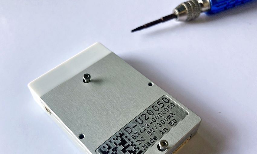
1 | The Hook-On-Device Datasheet
The Hook-On-Device
Introduction
The HookOnDevice (HOD) for UAS and other aircraft (such as helicopters) to transmit their own position data.
Thanks to its low weight, the HOD can be attached to any aircraft.
It contains an LTE modem and a SIM card. The device transmits its current GNSS position via LTE to the UAS
Traffic Management (UTM) system. The device is capable of receiving FLARM and ADSB from surrounding air
traffic and sending this data additionally to its own position to the UTM system. The UAS operator receives the UAS
own position and the position data of other relevant air traffic in the vicinity via the web based UTM tracker. At the
same time, the HOD transmits its position via FLARM (flight alarm). In this way, the aircraft also becomes visible to
other airspace users in the vicinity who use FLARM.
For more information please contact: support@aerobits.pl.
Revision: 28-July-2021 Document Number: 07052021
This document is subject to change without notice. For technical questions, contact: support@aerobits.pl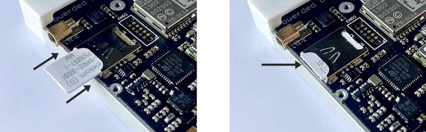
2 | The Hook-On-Device Datasheet
Contents
1 Technical parameters 4
1.1 Basic technical information . . . . . . . . . . . . . . . . . . . . . . . . . . . . . . . . . . . . . . . . 4
1.2 Main features . . . . . . . . . . . . . . . . . . . . . . . . . . . . . . . . . . . . . . . . . . . . . . . . . 4
2 Electrical specification 5
2.1 Basic electrical parameters . . . . . . . . . . . . . . . . . . . . . . . . . . . . . . . . . . . . . . . . 5
2.2 PIN definition . . . . . . . . . . . . . . . . . . . . . . . . . . . . . . . . . . . . . . . . . . . . . . . . . 5
2.3 LED indicators . . . . . . . . . . . . . . . . . . . . . . . . . . . . . . . . . . . . . . . . . . . . . . . . 6
3 Mechanical specification 7
3.1 Mechanical parameters . . . . . . . . . . . . . . . . . . . . . . . . . . . . . . . . . . . . . . . . . . 7
3.2 Dimensions . . . . . . . . . . . . . . . . . . . . . . . . . . . . . . . . . . . . . . . . . . . . . . . . . . 7
3.3 Connectors . . . . . . . . . . . . . . . . . . . . . . . . . . . . . . . . . . . . . . . . . . . . . . . . . . 7
4 Principle of operation 8
4.1 States of operation . . . . . . . . . . . . . . . . . . . . . . . . . . . . . . . . . . . . . . . . . . . . . 8
4.1.1 BOOTLOADER state . . . . . . . . . . . . . . . . . . . . . . . . . . . . . . . . . . . . . . . . 8
4.1.2 RUN state . . . . . . . . . . . . . . . . . . . . . . . . . . . . . . . . . . . . . . . . . . . . . . . 8
4.1.3 CONFIGURATION state . . . . . . . . . . . . . . . . . . . . . . . . . . . . . . . . . . . . . . . 8
4.2 Transitions between states . . . . . . . . . . . . . . . . . . . . . . . . . . . . . . . . . . . . . . . . 8
4.2.1 BOOTLOADER to RUN transition . . . . . . . . . . . . . . . . . . . . . . . . . . . . . . . . 8
4.2.2 RUN to CONFIGURATION transition . . . . . . . . . . . . . . . . . . . . . . . . . . . . . . . 9
4.2.3 CONFIGURATION to RUN transition . . . . . . . . . . . . . . . . . . . . . . . . . . . . . . . 9
4.2.4 CONFIGURATION to BOOTLOADER transition . . . . . . . . . . . . . . . . . . . . . . . . 9
5 UART configuration 10
6 Settings 11
6.1 Write settings . . . . . . . . . . . . . . . . . . . . . . . . . . . . . . . . . . . . . . . . . . . . . . . . 11
6.2 Read settings . . . . . . . . . . . . . . . . . . . . . . . . . . . . . . . . . . . . . . . . . . . . . . . . 11
6.3 Settings description . . . . . . . . . . . . . . . . . . . . . . . . . . . . . . . . . . . . . . . . . . . . 11
6.4 Errors . . . . . . . . . . . . . . . . . . . . . . . . . . . . . . . . . . . . . . . . . . . . . . . . . . . . . . 11
6.5 Command endings . . . . . . . . . . . . . . . . . . . . . . . . . . . . . . . . . . . . . . . . . . . . . 11
6.6 Uppercase and lowercase . . . . . . . . . . . . . . . . . . . . . . . . . . . . . . . . . . . . . . . . 12
6.7 Available settings . . . . . . . . . . . . . . . . . . . . . . . . . . . . . . . . . . . . . . . . . . . . . . 13
6.8 Example . . . . . . . . . . . . . . . . . . . . . . . . . . . . . . . . . . . . . . . . . . . . . . . . . . . . 14
7 Commands 15
7.1 Commands in BOOTLOADER and CONFIGURATION state . . . . . . . . . . . . . . . . . . . . . 15
7.1.1 AT+LOCK . . . . . . . . . . . . . . . . . . . . . . . . . . . . . . . . . . . . . . . . . . . . . . . 15
7.1.2 AT+BOOT . . . . . . . . . . . . . . . . . . . . . . . . . . . . . . . . . . . . . . . . . . . . . . . 15
7.2 Commands in CONFIGURATION state . . . . . . . . . . . . . . . . . . . . . . . . . . . . . . . . . 15
7.2.1 AT+CONFIG . . . . . . . . . . . . . . . . . . . . . . . . . . . . . . . . . . . . . . . . . . . . . . 15
7.2.2 AT+SETTINGS? . . . . . . . . . . . . . . . . . . . . . . . . . . . . . . . . . . . . . . . . . . . 15
7.2.3 AT+HELP . . . . . . . . . . . . . . . . . . . . . . . . . . . . . . . . . . . . . . . . . . . . . . . 15
7.2.4 AT+SETTINGS_DEFAULT . . . . . . . . . . . . . . . . . . . . . . . . . . . . . . . . . . . . . 16
7.2.5 AT+SERIAL_NUMBER . . . . . . . . . . . . . . . . . . . . . . . . . . . . . . . . . . . . . . . 16
7.2.6 AT+FIRMWARE_VERSION . . . . . . . . . . . . . . . . . . . . . . . . . . . . . . . . . . . . . 16
7.2.7 AT+REBOOT . . . . . . . . . . . . . . . . . . . . . . . . . . . . . . . . . . . . . . . . . . . . . 16
7.2.8 AT+REBOOT_BOOTLOADER . . . . . . . . . . . . . . . . . . . . . . . . . . . . . . . . . . . 16
7.3 Commands in RUN state . . . . . . . . . . . . . . . . . . . . . . . . . . . . . . . . . . . . . . . . . . 16
8 Protocols 17
8.1 Network communication modes . . . . . . . . . . . . . . . . . . . . . . . . . . . . . . . . . . . . 17
8.2 JSON Protocol . . . . . . . . . . . . . . . . . . . . . . . . . . . . . . . . . . . . . . . . . . . . . . . . 17
8.2.1 Status section . . . . . . . . . . . . . . . . . . . . . . . . . . . . . . . . . . . . . . . . . . . . 18
Revision: 28-July-2021 Document Number: 07052021
This document is subject to change without notice. For technical questions, contact: support@aerobits.pl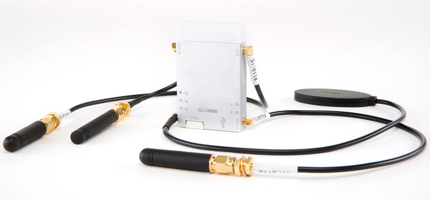
3       |                                                                                                             The Hook-On-Device                                          Datasheet

         8.2.2 GNSS section . . . . . . . .       .   .   .   .   .   .   .   .   .   .   .   .   .   .   .   .   .   .   .   .   .   .   .   .   .   .   .   .   .   .   .   .   .   .   .   .    19
         8.2.3 Sensor section . . . . . . .       .   .   .   .   .   .   .   .   .   .   .   .   .   .   .   .   .   .   .   .   .   .   .   .   .   .   .   .   .   .   .   .   .   .   .   .   20
         8.2.4 Raw ADS-B section . . . . .        .   .   .   .   .   .   .   .   .   .   .   .   .   .   .   .   .   .   .   .   .   .   .   .   .   .   .   .   .   .   .   .   .   .   .   .    21
         8.2.5 Processed ADS-B reports            .   .   .   .   .   .   .   .   .   .   .   .   .   .   .   .   .   .   .   .   .   .   .   .   .   .   .   .   .   .   .   .   .   .   .   .   22
         8.2.6 Processed FLARM reports            .   .   .   .   .   .   .   .   .   .   .   .   .   .   .   .   .   .   .   .   .   .   .   .   .   .   .   .   .   .   .   .   .   .   .   .   24
     8.3 MAVLink protocol . . . . . . . . . .     .   .   .   .   .   .   .   .   .   .   .   .   .   .   .   .   .   .   .   .   .   .   .   .   .   .   .   .   .   .   .   .   .   .   .   .   26
         8.3.1 ADS-B Aircraft message .           .   .   .   .   .   .   .   .   .   .   .   .   .   .   .   .   .   .   .   .   .   .   .   .   .   .   .   .   .   .   .   .   .   .   .   .   26
         8.3.2 FLARM Aircraft message .           .   .   .   .   .   .   .   .   .   .   .   .   .   .   .   .   .   .   .   .   .   .   .   .   .   .   .   .   .   .   .   .   .   .   .   .   26
         8.3.3 FLARM Collision message .          .   .   .   .   .   .   .   .   .   .   .   .   .   .   .   .   .   .   .   .   .   .   .   .   .   .   .   .   .   .   .   .   .   .   .   .   27

9 Quick start                                                                                                                                                                                     28
  9.1 Specification of used anntena . . . . . . . . . . .                             .   .   .   .   .   .   .   .   .   .   .   .   .   .   .   .   .   .   .   .   .   .   .   .   .   .   .   28
  9.2 Scope of delivery . . . . . . . . . . . . . . . . . . .                         .   .   .   .   .   .   .   .   .   .   .   .   .   .   .   .   .   .   .   .   .   .   .   .   .   .   .   28
  9.3 Inserting a SIM/chip card . . . . . . . . . . . . . . .                         .   .   .   .   .   .   .   .   .   .   .   .   .   .   .   .   .   .   .   .   .   .   .   .   .   .   .   29
  9.4 Installation . . . . . . . . . . . . . . . . . . . . . . . .                    .   .   .   .   .   .   .   .   .   .   .   .   .   .   .   .   .   .   .   .   .   .   .   .   .   .   .   30
      9.4.1 Recharging of batteries . . . . . . . . . . .                             .   .   .   .   .   .   .   .   .   .   .   .   .   .   .   .   .   .   .   .   .   .   .   .   .   .   .   30
      9.4.2 Usage of the Hook-On-Device Version 2                                     .   .   .   .   .   .   .   .   .   .   .   .   .   .   .   .   .   .   .   .   .   .   .   .   .   .   .   30
      9.4.3 Installation process . . . . . . . . . . . . . .                          .   .   .   .   .   .   .   .   .   .   .   .   .   .   .   .   .   .   .   .   .   .   .   .   .   .   .    31
      9.4.4 Important notices during installation . . .                               .   .   .   .   .   .   .   .   .   .   .   .   .   .   .   .   .   .   .   .   .   .   .   .   .   .   .    31

10 General information                                                                                             32
   10.1 Important safety notes . . . . . . . . . . . . . . . . . . . . . . . . . . . . . . . . . . . . . . . . . . 32

11 Revision history                                                                                                                                                                               33

Revision: 28-July-2021                                                                                                Document Number: 07052021
    This document is subject to change without notice. For technical questions, contact: support@aerobits.pl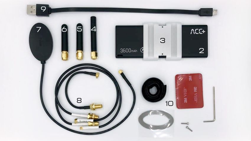
4 | The Hook-On-Device Datasheet
1 Technical parameters
1.1 Basic technical information
Parameter Description Typ. Unit
FLARM frequencies transmitter and receiver 868 MHz
highly dependent on antenna installation
FLARM range
(also at other airspace users)
ADSB frequency receiver 1090 MHz
can be reduced by the
ADSB range 250 km
user to limit data usage
GNSS oriented upwards (writing ”Pulse” facing up)
Antenna orientation
LTE / FLARM / ADSB oriented downwards
Dimension 58 x 38 x 9.5 mm
without antennas 35
with antennas 84
Weight grams
with USB and antennas 89
with all antennas and power bank 149
Table 1: General technical parameters.
1.2 Main features
• Connectivity: 4G LTE Cat1, GNSS, ADSB, FLARM wide band/multiconstellation/1090 MHZ/868MHz
• LTE modem to track aircraft via LTE
• Internal antennas: Builtin LTE antenna can be activated optionally
• External antennas: LTE, GNSS, FLARM and ADSB antennas
• Compatible with all FLARM systems in aircraft and UAS
• Licensed FLARM transceiver (0.025 Watt output power) broadcasting its own position
• Barometric sensor on board
• Programming via AT commands
• Simple plug&play integration
Revision: 28-July-2021 Document Number: 07052021
This document is subject to change without notice. For technical questions, contact: support@aerobits.pl5 | The Hook-On-Device Datasheet
2 Electrical specification
2.1 Basic electrical parameters
Parameter Value
6 pin JST (power and data) or mirco USB
External (power) connector
(power and data), MMCX (antennas)
5 V (external power supply, such as a power
Power supply
bank or aircraft’s power supply)
Power consumption < 400 mA
Table 2: General electrical parameters.
Figure 1: Appendant drawing of The HookOnDevice bottom.
2.2 PIN definition
PIN Color Name Function
1 GND Ground
2 NC Not connected
3 NC Not connected
4 TX MAVLink, AERO TXD
5 RX MAVLink, AERO RXD
6 +5 V Power supply (5 V/ 70 mA)
Table 3: Pin definition.
Revision: 28-July-2021 Document Number: 07052021
This document is subject to change without notice. For technical questions, contact: support@aerobits.pl6 | The Hook-On-Device Datasheet
2.3 LED indicators
LED Color Function
A (ADSB) White Flashing – reception of 1090 MHz avionics frame (ADSB)
F (FLARM) White Flashing – reception of valid FLARM frame (868 MHz)
Flashing – LTE communication initialized
Constant light – LTE communication in progress
L (LTE) White
Off – No mobil network, wait or change position
for better network coverage
Flashing – GNSS fixed
G (GNSS) White Off – No GNSS fix, wait or change position
for better satellite coverage
Constant light Power supply presence
P (Power) Green
Off – No power, connect or recharge power source
Table 4: LED indicators.
Revision: 28-July-2021 Document Number: 07052021
This document is subject to change without notice. For technical questions, contact: support@aerobits.pl7 | The Hook-On-Device Datasheet
3 Mechanical specification
3.1 Mechanical parameters
Parameter Value
Dimensions 58 mm x 38 mm x 9.5 mm
Weight 35 g
Table 5: Mechanical parameters of The HookOnDevice
3.2 Dimensions
Figure 2: Dimensions of The HookOnDevice
3.3 Connectors
Connector Type Example
Main Installed on board MOLEX, 473461001
Mating connector Common micro USB B connector
Antenna Installed on board MOLEX, 734150961
Mating connector ASMK025X174S11
Table 6: Connectors
Revision: 28-July-2021 Document Number: 07052021
This document is subject to change without notice. For technical questions, contact: support@aerobits.pl8 | The Hook-On-Device Datasheet
4 Principle of operation
During work module goes through multiple states. In each state operation of the module is different. Each state and
each transition is described in paragraphs below.
Figure 3: State machine of The HookOnDevice
4.1 States of operation
4.1.1 BOOTLOADER state
This is an initial state of The HookOnDevice after restart. Firmware update is possible here. Typically module
transits automatically to RUN state. It is possible to lock module in this state (prevent transition to RUN state) using
one of BOOTLOADER triggers. UART baud is constant and is set to 115200bps. After powering up module, it
stays in this state for up to 3 seconds. If no BOOTLOADER trigger is present, module will transit to RUN state.
Firmware upgrade is possible using Micro ADSB App software. For automated firmware upgrading scenarios,
aerobits_updater software is available. To acquire this program please contact: support@aerobits.pl.
4.1.2 RUN state
In this state module is working and receiving the data from aircrafts. It uses selected protocol to transmit received
and decoded data to the host system. In this state of operation module settings are loaded from nonvolatile internal
memory, including main UART interface’s baud.
4.1.3 CONFIGURATION state
In this mode change of stored settings is possible. Operation of the module is stopped and baud is set to fixed
115200bps. Change of settings is done by using ATcommands. Changes to settings are stored in nonvolatile
memory on exiting this state. Additional set of commands is also available in this state, allowing to e.g. reboot
module into BOOTLOADER state, check serial number and firmware version. It is possible to lock module in this
state (similarly to BOOTLOADER) using suitable command.
4.2 Transitions between states
For each of state transitions, different conditions must be met, which are described below. Generally, the only stable
state is RUN. Module always tends to transit into this state. Moving to other states requires host to take some action.
4.2.1 BOOTLOADER to RUN transition
BOOTLOADER state is semistable: the module requires additional action to stay in BOOTLOADER state. The
transition to RUN state will occur automatically after short period of time if no action will be taken. To prevent
transition from BOOTLOADER state, one of following actions must be processed:
• Send AT+LOCK=1 command while device is in BOOTLOADER state (always after power on for up to 3s)
• Send AT+REBOOT_BOOTLOADER command in CONFIGURATION state. This will move to BOOTLOADER
state and will lock module in this state.
Revision: 28-July-2021 Document Number: 07052021
This document is subject to change without notice. For technical questions, contact: support@aerobits.pl9 | The Hook-On-Device Datasheet
If none of above conditions are met, the module will try to transit into RUN state. Firstly it will check firmware integrity.
When firmware integrity is confirmed, module will transit into RUN state, if not, it will stay in BOOTLOADER state.
To transit into RUN state:
• If module is locked, send AT+LOCK=0 command
When module enters RUN mode it will send AT+RUN_START command.
4.2.2 RUN to CONFIGURATION transition
To transit from RUN into CONFIGURATION state, host should do one of the following:
• Send AT+CONFIG=1 (using current baud).
When module leaves RUN state it sends AT+RUN_END message, then AT+CONFIG_START message on entering
CONFIGURATION state. The former is sent using baud from settings, the latter always uses 115200bps baud.
4.2.3 CONFIGURATION to RUN transition
To transit from CONFIGURATION into RUN state, host should do one of the following:
• Send AT+CONFIG=0 command.
When module leaves CONFIGURATION state it sends AT+CONFIG_END message, then AT+RUN_START message
on entering RUN state. The former is always sent using 115200bps baud, the latter uses baud from settings.
4.2.4 CONFIGURATION to BOOTLOADER transition
To transit from CONFIGURATION into BOOTLOADER state, host should do one of the following:
• Send AT+REBOOT_BOOTLOADER command.
• Send AT+REBOOT and when module enters BOOTLOADER state, prevent transition to RUN state.
When entering the bootloader state, the module sends AT+BOOTLOADER_START .
Revision: 28-July-2021 Document Number: 07052021
This document is subject to change without notice. For technical questions, contact: support@aerobits.pl10 | The Hook-On-Device Datasheet
5 UART configuration
Communication between module and host device is done using UART interface.
The UART interface uses settings as described in table 7.
UART Settings
Parameter Min. Typ. Max Unit
Baud 115200 bps
Stop Bits Number 1
Flow Control None
Parity Bit None
Table 7: UART settings.
Revision: 28-July-2021 Document Number: 07052021
This document is subject to change without notice. For technical questions, contact: support@aerobits.pl11 | The Hook-On-Device Datasheet
6 Settings
In RUN state, operation of the module is determined based on stored settings. Settings can be changed in CON
FIGURATION state using ATcommands. Settings can be written and read.
NOTE: New values of settings are saved in nonvolatile memory when transitioning from CONFIGURATION
to RUN state.
Settings are restored from nonvolatile memory during transition from BOOT do RUN state. If settings become
corrupted due to memory fault, power loss during save, or any other kind of failure, the settings restoration will fail,
loading default values and displaying the AT+ERROR (Settings missing, loaded default) message as a
result. This behavior will occur for each device boot until new settings are written by the user.
6.1 Write settings
After writing a new valid value to a setting, an AT+OK response is always sent.
AT+SETTING=VALUE
For example AT+PROTOCOL=1
Response: AT+OK
6.2 Read settings
AT+SETTING?
For example: AT+PROTOCOL?
Response: AT+PROTOCOL=1
6.3 Settings description
AT+SETTING=?
For example: AT+PROTOCOL=?
Response:
Setting: PROTOCOL
Description: Selected protocol (0: NONE, 2: CSV, 3: MAVLINK)
Type: Integer decimal
Range (min.): 0
Range (max.): 5
Is preserved: 1
Is restart needed: 0
6.4 Errors
Errors are reported using following structure:
AT+ERROR (DESCRIPTION)
DESCRIPTION is optional and contains information about error.
6.5 Command endings
Every command must be ended with one of the following character sequences: “\n”, “\r” or “\r\n”. Commands without
suitable ending will be ignored.
Revision: 28-July-2021 Document Number: 07052021
This document is subject to change without notice. For technical questions, contact: support@aerobits.pl12 | The Hook-On-Device Datasheet
6.6 Uppercase and lowercase
All characters (except preceding AT+) used in command can be both uppercase and lowercase, so following com
mands are equal:
AT+PROTOCOL?
AT+pRoToCoL?
NOTE: This statement is true in configuration state, not in bootloader state. in bootloader state all letters
must be uppercase.
Revision: 28-July-2021 Document Number: 07052021
This document is subject to change without notice. For technical questions, contact: support@aerobits.pl13 | The Hook-On-Device Datasheet
6.7 Available settings
Setting Min Max Def Comment
BAUDRATE 0 2 0 Baudrate in RUN state
0 115200bps
1 921600bps
2 3000000bps
GNSS_LOG 0 2 0 GNSS NMEA forwarding
0 No forwarding
1 RMC Messages only
2 All
FLARM_LOG 0 2 0 FLARM debugging (1 basic, 2 detailed)
FLARM_TX 0 1 1 Flarm TX enabled
FLARM_RX 0 1 1 Flarm RX enabled
FLARM_LOG 0 2 0 Flarm debugging (1 basic, 2 detailed)
FLARM_AIRCRAFT_TYPE 0 15 0 Flarm aircraft type (0 UNKNOWN, 1 GLIDER, 2 TOW
PLANE, 3 HELICOPTER, 4 PARACHUTE, 5 DROPPLANE,
6 FIXED_HG, 7 SOFT_HG, 8 ENGINE, 9 JET, 10 UFO,
11 BALLOON, 12 AIRSHIP, 13 UAV, 15 STATIC)
IMU_LOG 0 1 0 Show inertial measrurement unit log
TT_LOG 0 1 0 Show TT log
LTE_LOG 0 1 0 Show LTE log
LTE_EXTERNAL_ANTENNA 0 1 0 Enable external LTE ANTENA
UAS_REGISTRATION_PREFIX UAS registration identity
UAS_SERIAL_NO UAS registration number
UAS_TYPE 0 3 0 Specification of the type of UAS
UAS_FLIGHT_TYPE 0 4 0 Flight type of UAS
UAS_MISSION_TYPE 0 14 0 Mission type of UAS
UAS_FLIGHT_STATUS 0 5 0 Flight status of UAS
UAS_FAILURE_STATUS 0 10 0 Failure status of UAS
APN_NAME LTE APN name
APN_USER LTE APN user name
APN_PASSWORD LTE APN user password
APN_TYPE 0 5 0 Type of APN (0 auto, 1 GSM, 2 CDMA, 3 WCDMA, 4
EVDO, 5 LTE)
APN_LTE_BANDS 80005 LTE frequency bands
MQTT_LOG 0 1 0 Show MQTT log
MQTT_TLS 0 1 0 Enables TLS in MQTT
MQTT_BROKER_ADDRESS MQTT broker address
MQTT_BROKER_PORT 0 065535 0 MQTT broker port
MQTT_USER MQTT user name
MQTT_PASS MQTT broker password
MQTT_CLIENT_ID MQTT client ID, left blank to use IMSI
MQTT_KEEPALIVE 60 3600 60 MQTT keepalive interval
MQTT_WEBSOCKET 0 1 0 Use websocket when connecting to broker (0 disable, 1 en
able)
FILTER_DISTANCE 0 25000 25000 Range of distance filter (Meters) (0 Disabled)
GNSS_SYSTEMS FFFF GNSS systems bitmask (GPS / SBAS / GALILEO / BEIDOU /
IMES / QZSS / GLONASS)
CSV_EMITTER_CAT 0 13 13 Device’s emitter category displayed in CSV protocol
GBSAS_OWNPOS_ENABLE 0 1 0 Enable GBSAS own position reporting
CSV_TOPIC CSV plot MQTT topic
ADSB_TOPIC ADSB plot MQTT topic
FLARM_TOPIC FLARM plot MQTT topic
TELEMETRY_TOPIC JSON Telemetry plot MQTT topic
MLAT_TOPIC MLAT plot MQTT topic
AUX_DATA_TOPIC Topic for transmitting data received by aux port
PRESSURE_LOG 0 1 0 Show barometer log
SETTINGS_DEFAULT Load default settings
Table 8: Settings
Revision: 28-July-2021 Document Number: 07052021
This document is subject to change without notice. For technical questions, contact: support@aerobits.pl14 | The Hook-On-Device Datasheet 6.8 Example As an example, to switch The HookOnDevice module to CSV protocol, one should send following commands. “” is a response. > AT+OK\r\n > AT+OK\r\n >> AT+OK\r\n
15 | The Hook-On-Device Datasheet
7 Commands
Apart from settings, module supports set of additional commands. Format of this commands are similar to those
used for settings, but they do not affect operation of module in RUN state.
7.1 Commands in BOOTLOADER and CONFIGURATION state
7.1.1 AT+LOCK
AT+LOCK=1 Set lock to enforce staying in BOOTLOADER or CONFIGURATION state
AT+LOCK=0 Remove lock
AT+LOCK? Check if lock is set
7.1.2 AT+BOOT
AT+BOOT? Check if module is in BOOTLOADER state
Response:
AT+BOOT=0 module in CONFIGURATION state
AT+BOOT=1 module in BOOTLOADER state
7.2 Commands in CONFIGURATION state
7.2.1 AT+CONFIG
AT+CONFIG=0 Transition to RUN state.
AT+CONFIG? Check if module is in CONFIGURATION state.
Response:
AT+CONFIG=0 module in RUN state
AT+CONFIG=1 module in CONFIGURATION state
7.2.2 AT+SETTINGS?
AT+SETTINGS? List all settings. Example output:
AT+PROTOCOL=2
AT+SUBPROTOCOL=0
AT+BAUDRATE=0
7.2.3 AT+HELP
AT+HELP Show all settings and commands with descriptions. Example output:
SETTINGS:
AT+PROTOCOL=2 [Selected protocol (0: NONE, 2: CSV, 3: MAVLINK)]
AT+SUBPROTOCOL=0 [Subprotocol of selected protocol]
COMMANDS:
AT+HELP [Show this help]
AT+TEST [Responds "AT+OK"]
AT+SETTINGS_DEFAULT [Load default settings]
AT+REBOOT [Reboot system]
Revision: 28-July-2021 Document Number: 07052021
This document is subject to change without notice. For technical questions, contact: support@aerobits.pl16 | The Hook-On-Device Datasheet
7.2.4 AT+SETTINGS_DEFAULT
AT+SETTINGS_DEFAULT Set all settings to their default value.
7.2.5 AT+SERIAL_NUMBER
AT+SERIAL_NUMBER? Read serial number of module.
Response:
AT+SERIAL_NUMBER=070001337
7.2.6 AT+FIRMWARE_VERSION
AT+FIRMWARE_VERSION? Read firmware version of module.
Response:
AT+FIRMWARE_VERSION=10101017(May 11 2018)
7.2.7 AT+REBOOT
AT+REBOOT Restart module.
7.2.8 AT+REBOOT_BOOTLOADER
AT+REBOOT_BOOTLOADER Restart module to BOOTLOADER state.
NOTE: This command also sets lock.
7.3 Commands in RUN state
AT+CONFIG=1 transition to CONFIGURATION state.
NOTE: This command also sets lock.
Revision: 28-July-2021 Document Number: 07052021
This document is subject to change without notice. For technical questions, contact: support@aerobits.pl17 | The Hook-On-Device Datasheet
8 Protocols
8.1 Network communication modes
HOD communicates through the network using MQTT 3.1 protocol. Connection can be configured to use username
and password authentication, as well as TLS encryption. All data is transmitted into single MQTT topic.
8.2 JSON Protocol
HOD uses JSON compliant with RFC 8259 to transmit its messages. Each message is encoded as separate JSON
object, without any excess whitespace, consisting of fields described in table 9. If multiple objects are sent in same
message, they are concatenated without any delimiter.
Name Description Value type
{
"src": "230000001", HOD’s serial number. String
"ts": 69061337, Timestamp in milliseconds, relative to last UTC Unsigned integer
midnight. Value 69061337 encodes 19:11:01.337.
"ver": 1, JSON protocol version. See details below. Unsigned integer
"gnss": {...} One of the data fields, described in subchapters Object or array
below.
}
Table 9: Description of main JSON fields.
NOTE: The order of JSON object fields in any part of message may vary between firmware revisions and
messages.
Some JSON objects have fields, of which values may sometimes be unknown. In this case, they are skipped in
JSON output. In following chapters, each of those fields are explicitly marked as ommitable.
NOTE: In case of JSON objects consisting of only ommitable fields, if none of them are set, the whole object
is omitted.
The "ver" field indicates JSON protocol version. Future ICD versions may introduce additional fields without chang
ing the version number. If a breaking change occurs in HOD JSON specification, the version number is guaranteed
to be incremented.
NOTE: The version number of JSON protocol described in this document is 1.
Revision: 28-July-2021 Document Number: 07052021
This document is subject to change without notice. For technical questions, contact: support@aerobits.pl18 | The Hook-On-Device Datasheet
8.2.1 Status section
The "status" section contains status information related to HOD itself. The example JSON message with "status"
section fields described, is shown in table 10.
JSON field Description Value type
{
"src": "230000001",
"ts": 69061337, see table 9.
"ver": 1,
"status": {
"fw": "30903679(Jan 15 2021)", String
Firmware version, with same syntax as
AT+FIRMWARE_VERSION command.
Value 30903679 is version 3.9.3.679.
"lte": { LTE connection information.
"rssnr": 11, Reference Signal Signal to Noise Unsigned integer
Ratio, in dB. Omitted if unknown.
"rsrp": 90.0, Reference Signal Received Power, Floating point
in dBm. Omitted if unknown.
"rsrq": 12.4, Reference Signal Received Quality, Floating point
in dBm. Omitted if unknown.
"cid": 4327240 Cell id. Omitted if unknown. Unsigned integer
}
}
}
Table 10: Descriptions of JSON Status section fields.
Revision: 28-July-2021 Document Number: 07052021
This document is subject to change without notice. For technical questions, contact: support@aerobits.pl19 | The Hook-On-Device Datasheet
8.2.2 GNSS section
The "gnss" section contains basic GNSS information. This message is sent once per second. The example JSON
message with "gnss" section fields described, is shown in table 11.
JSON field Description Value type
{
"src": "230000001",
"ts": 69061337, see table 9.
"ver": 1,
"gnss": {
"fix": 1, Set to 1 if onboard GNSS currently has fix, otherwise Unsigned integer
0.
Last known latitude.
"lat": 53.428544, Omitted if there was no GNSS fix since device boot. Floating point
Last known longitude.
"lon": 14.552812, Omitted if there was no GNSS fix since device boot. Floating point
Last known WGS84 Altitude, in meters.
"alt": 499.6, Omitted if there was no GNSS fix since device boot. Floating point
Geoid separation: local height of mean sea level
"mslHeight": 48.0, above ellipsoid. Omitted if unknown. Floating Point
"track": 127.3, Track angle, 0°..360°. Omitted if unknown. Floating point
"hVelo": 10.5, Horizontal velocity, in knots. Omitted if unknown. Floating point
"acc": {
"lat": 5.2, Accuracy of latitude, in meters. Omitted if unknown. Floating point
"lon": 2.1, Accuracy of longitude, in meters. Omitted if unknown. Floating point
"alt": 3.6 Accuracy of altitude, in meters. Omitted if unknown. Floating point
}
}
}
Table 11: Descriptions of JSON GNSS section fields.
Revision: 28-July-2021 Document Number: 07052021
This document is subject to change without notice. For technical questions, contact: support@aerobits.pl20 | The Hook-On-Device Datasheet
8.2.3 Sensor section
The "sensor" section contains values acquired from miscellaneous sensors present in HOD hardware and consists
of fields shown in table 12. This message is sent once per second. All fields are optional they are sent only if
apropriate sensor is enabled.
JSON field Description Value type
{
"src": "230000001",
"ts": 69061337, see table 9.
"ver": 1,
"sensor": {
"pressure": 1013.25, Current pressure sensor value, in hPa. Floating point
"temp": 20.5, Current temperature sensor value, in degrees Celsius. Floating point
"acc": [
11.2, 0.31, 0.5 Accelerometer readings for each axis, in g. Floating point
],
"gyro": [
11.2, 0.31, 0.5 Gyroscope readings for each axis, in deg/s. Floating point
],
"mag": [
11.2, 0.31, 0.5 Magnetometer readings for each axis, in µT. Floating point
]
}
}
Table 12: Descriptions of JSON sensor section fields.
Revision: 28-July-2021 Document Number: 07052021
This document is subject to change without notice. For technical questions, contact: support@aerobits.pl21 | The Hook-On-Device Datasheet
8.2.4 Raw ADS-B section
The "raw" section contains raw, unprocessed and unfiltered ADSB frames gathered by HOD, which can be used
e.g. for multilateration and other lowlevel analysis. Raw messages are encoded as JSON array with at least one
entry. Each array entry is a separate array containing values as described in table 13
JSON field Description Value type
{
"src": "230000001",
"ts": 69061337, see table 9.
"ver": 1,
"raw": [
[
"18A9725A4C842D", Raw frame bytes, formatted as uppercase String
hexadecimal. Short ModeS frames encode 7
bytes, long frames contain 14 bytes.
696, Signal strength, in mV. Unsigned integer
68, Signal quality, in mV. Unsigned integer
"295CAB573A77" UTCcalibrated time of reception, formatted as String
uppercase hexadecimal, in nanoseconds. Example
translates to 12:37:57.988350583
]
]
}
Table 13: Descriptions of JSON raw ADSB section fields.
NOTE: Due to constrained throughput of HOD communication, transmission of some raw frames may be
skipped in heavy aircraft traffic situations.
Revision: 28-July-2021 Document Number: 07052021
This document is subject to change without notice. For technical questions, contact: support@aerobits.pl22 | The Hook-On-Device Datasheet
8.2.5 Processed ADS-B reports
The "adsb" section contains aircraft information determined by HOD’s internal ADSB processing engine. The
messages are encoded as JSON array with at least one entry. Each entry is an object consisting of fields denoted
in table 14. Reports for each ADSB aircraft are updated once every second.
JSON field Description Value type
{
"src": "230000001",
"ts": 69061337, see table 9.
"ver": 1,
"adsb": [
{
"icao": "DABABE", ICAO address, 24bit value encoded in uppercase String
hexadecimal, with leading zeros.
"sigStr": 696, Signal strength. Unsigned integer
"sigQ": 68, Signal quality. Unsigned integer
"fps": 5, Number of raw ModeS frames received from Unsigned integer
aircraft during last second.
"lat": 53.428544, Latitude. Omitted if position is unknown. Floating point
"lon": 14.552812, Longitude. Omitted if position is unknown. Floating point
"baroAlt": 1725, Barometric altitude, in feet. Omitted if unknown. Signed integer
"geoAlt": 1712, Geometric altitude, in feet. Omitted if unknown. Signed integer
"track": 72.18, Track angle, 180°..180°. Omitted if unknown. Floating point
"hVelo": 10.5, Horizontal velocity, in knots. Omitted if unknown. Floating point
"vVelo": 50, Vertical velocity, in ft/min, positive value is upwards. Signed integer
Omitted if unknown.
"ident": "TEST8", Callsign, up to 8 chars. Omitted if unknown. String
"squawk": "7232", Squawk, 8 octal digits. Omitted if unknown. String
"ecat": 13, Emitter category code, see table 15. Omitted if Unsigned integer
unknown.
NACP value, as described in ED102A.
"nacp": 3, Omitted if value is 0 (unknown). Unsigned integer
NACV value, as described in ED102A.
"nacv": 1, Omitted if value is 0 (unknown). Unsigned integer
NICBARO value, as described in ED102A.
"nicBaro": 1, Omitted if value is 0. Unsigned integer
NIC value, as described in ED102A.
"nic": 2, Omitted if value is 0 (unknown). Unsigned integer
Set to 1 if plane is on earth surface.
"surf": 1 Omitted if plane is in air or unknown. Unsigned integer
}
]
}
Table 14: Descriptions of JSON ADSB section fields.
The emitter category values returned in "ecat" field is shown in table 15.
Revision: 28-July-2021 Document Number: 07052021
This document is subject to change without notice. For technical questions, contact: support@aerobits.pl23 | The Hook-On-Device Datasheet
"ecat" value Description
0 Unknown.
1 Light (below 15500 lbs.).
2 Small (15500 75000 lbs.).
3 Large (75000 300000 lbs.).
4 HighVortex Large (aircraft such as B757).
5 Heavy (above 300000 lbs.).
6 High performance (above 5g acceleration and above 400 knots).
7 Rotorcraft.
8 Reserved.
9 Glider, Sailplane.
10 LighterThanAir.
11 Parachutist, Skydiver.
12 Ultralight, hangglider, paraglider.
13 Reserved.
14 Unmanned Aerial Vehicle.
15 Space, Transatmospheric Vehicle.
16 Reserved.
17 Surface Vehicle Emergency Vehicle.
18 Surface Vehicle Service Vehicle.
19 Point Obstacle (includes Tethered Ballons).
20 Cluster obstacle.
21 Line obstacle.
Table 15: ADSB emitter category values in JSON protocol.
Revision: 28-July-2021 Document Number: 07052021
This document is subject to change without notice. For technical questions, contact: support@aerobits.pl24 | The Hook-On-Device Datasheet
8.2.6 Processed FLARM reports
The "flarm" section contains aircraft information determined by HOD’s internal FLARM processing engine. The
messages are encoded as JSON array with at least one entry. Each entry is an object consisting of fields denoted
in table 16. Reports for each FLARM aircraft are updated once every second.
JSON field Description Value type
{
"src": "230000001",
"ts": 69061337, see table 9.
"ver": 1,
"flarm": [
{
Aircraft id type.
"idType": 1, 0: randomized, 1: ICAO, 2: FLARM. Unsigned integer
"id": "DABABE", Aircraft id, 32bit value encoded in uppercase string
hexadecimal, with leading zeros.
"type": 13, Aircraft type, see table 17. Unsigned integer
"danger": 1, Danger level (13). Omitted if 0 (no danger) Unsigned integer
"lat": 53.428544, Latitude. Floating point
"lon": 14.552812, Longitude. Floating point
"alt": 525, Barometric altitude, in meters. Signed integer
"hVelo": 50, Horizontal velocity, in m/s. Unsigned integer
"vVelo": 200, Vertical velocity, in cm/s. Unsigned integer
"movMode": 5, Unsigned integer
Movement mode.
1: stationary, 4: circling right, 5: flying, 7: circling left.
"stealth": 1, Set to 1 if target has Stealth flag set, otherwise Unsigned integer
omitted.
"notrack": 1 Set to 1 if target has Notrack flag set, otherwise Unsigned integer
omitted.
}
]
}
Table 16: Descriptions of JSON FLARM section fields.
The list of possible FLARM “Aircraft type” values returned in "type" field is shown in table 17.
Revision: 28-July-2021 Document Number: 07052021
This document is subject to change without notice. For technical questions, contact: support@aerobits.pl25 | The Hook-On-Device Datasheet
"type" value Description
0 Reserved.
1 Glider, Motor glider.
2 Tow plane, tug plane.
3 Helicopter, gyrocopter, rotocraft.
4 Skydiver, parachute.
5 Drop plane for skydivers.
6 Hang glider (hard).
7 Hang glider (soft).
8 Aircraft with reciprocating engine.
9 Aircraft with jet / turboprop engine.
10 Reserved.
11 Balloon (hot, gas, weather, static).
12 Airship, blimp, zeppelin.
13 Unmanned Aerial Vehicle (UAV).
14 Reserved.
15 Static obstacle.
Table 17: FLARM Aircraft type values in JSON protocol.
Revision: 28-July-2021 Document Number: 07052021
This document is subject to change without notice. For technical questions, contact: support@aerobits.pl26 | The Hook-On-Device Datasheet
8.3 MAVLink protocol
The HookOnDevice can be switched to use MAVLink protocol. This can be achieved by altering PROTOCOL
setting. When MAVLink protocol is used, module is sending list of aircrafts every second. MAVLink messages have
standarized format, which is well described on official protocol webpage (mavlink.io/en/messages).
8.3.1 ADS-B Aircraft message
Aircrafts are encoded using ADSB_VEHICLE message (mavlink.io/en/messages/common.html#ADSB_VEHICLE).
MAVLink message contains several data fields which are described below.
Field Name Type Description
ICAO_address uint32_t ICAO address
lat int32_t Latitude, expressed as degrees * 1E7
lon int32_t Longitude, expressed as degrees * 1E7
altitude_type uint8_t Type from ADSB_ALTITUDE_TYPE enum
altitude int32_t Barometric/Geometric Altitude (ASL), in millimeters
heading uint16_t Course over ground in centidegrees
hor_velocity uint16_t The horizontal velocity in centimeters/second
ver_velocity uint16_t The vertical velocity in centimeters/second, positive is up
callsign char[9] The callsign, 8 chars + NULL
emitter_type uint8_t Type from ADSB_EMITTER_TYPE enum
tslc uint8_t Time since last communication in seconds
flags uint16_t Flags to indicate various statuses including valid data fields
squawk uint16_t Squawk code
Table 18: MAVLink ADSB_VEHICLE message description
The ADSB vehicle may transmit barometric, as well as geometric altitude. The SUBPROTOCOL setting allows for
toggling altitude transmit priority:
• When set to 0, altitude field will be filled with geometric altitude first. If not available, barometric altitude will be
used.
• When set to 1, barometric altitude wil be preferred.
8.3.2 FLARM Aircraft message
Aircrafts reported by FLARM use ADSB_VEHICLE message in same format as described in ADSB Aircraft message
section, with following restrictions:
• The FLARM “Aircraft Type” field is translated to MAVLink “Emitter Category” field as shown in table 19.
• ICAO field contains FLARM id value.
Revision: 28-July-2021 Document Number: 07052021
This document is subject to change without notice. For technical questions, contact: support@aerobits.pl27 | The Hook-On-Device Datasheet
Aircraft Emitter
Type Aircraft Type description Category Emitter Category description
index index
0 Reserved 0 No information
1 Glider, Motor glider 9 Glider
2 Tow plane, tug plane 1 Light
3 Helicopter, gyrocopter, rotocraft 7 Rotorcraft
4 Skydiver, parachute 11 Parachute
5 Drop plane for skydivers 1 Light
6 Hang glider (hard) 12 Ultra light
7 Hang glider (soft) 12 Ultra light
8 Aircraft with reciprocating engine 1 Light
9 Aircraft with jet / turboprop engine 3 Large
10 Reserved 0 No information
11 Balloon (hot, gas, weather, static) 10 Lighter than air
12 Airship, blimp, zeppelin. 10 Lighter than air
13 Unmanned Aerial Vehicle (UAV) 14 UAV
14 Reserved 0 No information
15 Static obstacle 0 No information
Table 19: FLARM Aircraft Type to Emitter Category translation table
8.3.3 FLARM Collision message
Apart from ADSB messages, FLARM subsystem emits COLLISION messages (mavlink.io/en/messages/common.html#COLLISI
Detailed information about given aircraft can be obtained from ADSB_VEHICLE message directly preceding given
COLLISION message.
NOTE: The Mavlink protocol is sent via the JST connector.
Revision: 28-July-2021 Document Number: 07052021
This document is subject to change without notice. For technical questions, contact: support@aerobits.pl28 | The Hook-On-Device Datasheet
9 Quick start
Figure 4: Combination overview
9.1 Specification of used anntena
Connector Part number Connector type
ADSB DELTA1A/X/SMAM/S/S/11 GSM/GPRS, 3G and Ism Stubby Antenna SMA Male
GNSS PulseLarsen Antennas GNSSCGMSMA GPS Antenna SMA Male
FLARM TG.22.0111 GSM/GPRS Antenna SMA Male
LTE TG.22.0111 GSM/GPRS Antenna SMA Male
Table 20: Description of commonly used anntena
9.2 Scope of delivery
1. HookOnDevice
2. Power bank 3600mAh
3. Mounting bracket for HOD and power bank on drone
4. ADSB antenna (GSM/GPRS, 3G and Ism Stubby Antenna SMA Male)
5. FLARM antenna (GSM/GPRS Antenna SMA Male)
6. LTE antenna (GSM/GPRS Antenna SMA Male)
7. GNSS antenna (GPS/LTE Antenna MMCX)
8. 2x MMCX > SMA cable (250mm), 1 x MMCX > SMA cable (100mm)
9. USB cable
10. 2 x Hook&loop, 2 x mounting tapes, 2 x M1.6 screws and allen key
Revision: 28-July-2021 Document Number: 07052021
This document is subject to change without notice. For technical questions, contact: support@aerobits.pl29 | The Hook-On-Device Datasheet
Figure 5: HOD equipment kit
NOTE: LTE and FLARM antennas are identical and can be used interchangeably.
9.3 Inserting a SIM/chip card
To work properly the HOD V2 needs a valid SIM card. Recommended way to change/insert SIM card is described
below.
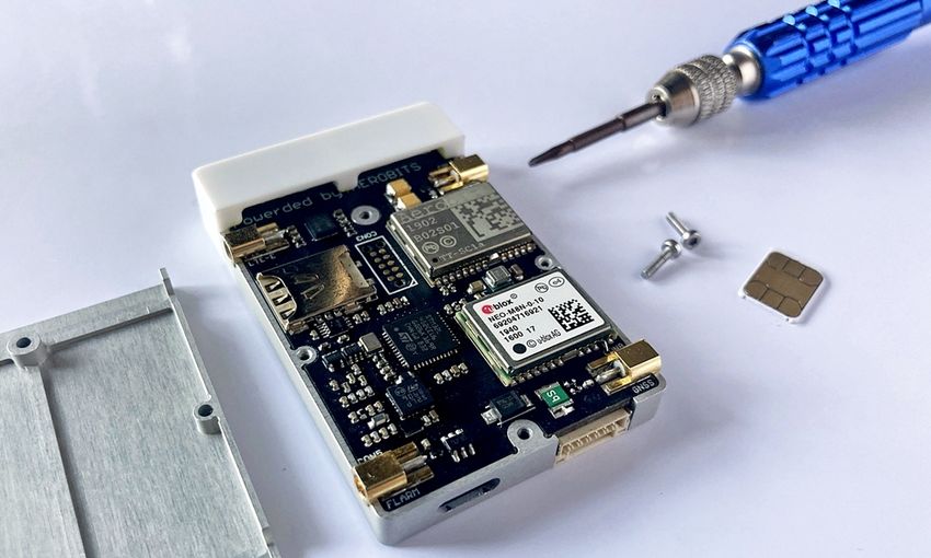
1. Disconnect module and unmount cover.
Revision: 28-July-2021 Document Number: 07052021
This document is subject to change without notice. For technical questions, contact: support@aerobits.pl30 | The Hook-On-Device Datasheet
Ensure that you have HOD disconnected and take off module cover. To unmount cover you will need a asterisk
screwdriver.
2. Find SIM card slot and insert SIM card.
Insert SIM card into slot visible on the picture above. A simple way to do it is to grab SIM with tweezers and push it
carefully directly into slot.
9.4 Installation
9.4.1 Recharging of batteries
The HOD V2 uses an external power source (such as the supplied power bank), which can be recharged with the
enclosed USB cable.
9.4.2 Usage of the Hook-On-Device Version 2
• Can be used for UAVs
• Can be used for all other air traffic such as helicopters, airplanes, gliders, etc.
Revision: 28-July-2021 Document Number: 07052021
This document is subject to change without notice. For technical questions, contact: support@aerobits.pl31 | The Hook-On-Device Datasheet
9.4.3 Installation process
1. Click the antennas into their respective slots on the device
2. Connect the device to a power supply (via USB or JST connector)
3. Secure the device and the antennas to the UAV or the aircraft and consider the important notices for the
installation given below. Securing all parts can be done with e.g. adhesive tape, table ties, Velcro tape,
specially designed mounts etc. and is unique to every vehicle. Always ensure a secure mount of all parts
before taking off.
4. The UAV or aircraft is ready to fly
NOTE: Once powered up, the device communicates its status via the LED descriptions mentioned in section
above.
9.4.4 Important notices during installation
• Keep separation between antennas and do not cross over antenna cables.
• GNSS antenna should be directed to the sky for optimal satellite signal reception.
• The external LTE antenna should be placed underneath the vehicle ideally in a vertical orientation facing
towards the ground.
NOTE: The device has an additional internal LTE antenna, which can be used instead of the external
one, if the signal strength in the vicinity is sufficient. To switch from external to internal or vice versa
the respective setting has to be changed in the software parameters via the downloadable Droniq HOD
V1 software. Settings are: External LTE antenna = 1 for external use or External LTE antenna = 0 for
internal.
• FLARM antenna should be placed in such a way to potentially “see” all other air traffic in the vicinity of the
vehicle (e.g. mounted facing in the main direction of flight of the vehicle).
• ADSB antenna like FLARM antenna (
NOTE: Since the typical ADSB signal strength is far greater than the one of FLARM the antenna mount
ing position is less crucial in comparison to FLARM and can be compromised in FLARMs favor).
• It is necessary to protect the device against vibrations of the vehicle as good as possible.
• The device is not secured against water, hence using it during rain or in wet conditions is not permitted.
Revision: 28-July-2021 Document Number: 07052021
This document is subject to change without notice. For technical questions, contact: support@aerobits.pl32 | The Hook-On-Device Datasheet
10 General information
10.1 Important safety notes
NOTE: When using the HookOnDevice Version 2 the following safety notes must be followed to reduce
injuries, accidents and short circuit to a minimum.
1. The manual must be read carefully.
2. All instructions must be followed.
3. Medical equipment (such as hearing aids, pace makers, etc.) which are not shielded properly, can be affected
in their functions. Please inform your doctor if this could be the case.
4. The device is operating with a voltage 5V.
5. Do not open the device, there are no parts that can be serviced by the user. Opening the device leads to the
loss of warranty and infringes the general terms and conditions.
6. The user is solely responsible for the risk while using this device. Droniq and the manufacturer are not respon
sible for any injuries or accidents that are a result of improper use.
Revision: 28-July-2021 Document Number: 07052021
This document is subject to change without notice. For technical questions, contact: support@aerobits.pl33 | The Hook-On-Device Datasheet
11 Revision history
Date Revision Changes
05May2021 1 Initial release.
28July2021 2 Available settings and protocols updated.
Table 21: Revision history.
Revision: 28-July-2021 Document Number: 07052021
This document is subject to change without notice. For technical questions, contact: support@aerobits.pl34 | The Hook-On-Device Datasheet
Please read carefully
Information contained in this document is provided solely in connection with Aerobits products. Aerobits reserves the
right to make changes, corrections, modifications or improvements to this document, and to products and services
described herein at any time, without notice. All Aerobits products are sold pursuant to our own terms and conditions
of sale. Buyers are solely responsible for the choice, selection and use of the Aerobits products and services
described herein, and Aerobits assumes no liability whatsoever, related to the choice, selection or use of Aerobits
products and services described herein. No license, express or implied, by estoppel or otherwise, to any intellectual
property rights is granted under this document. If any part of this document refers to any third party products or
services, it shall not be deemed a license granted by Aerobits for use of such third party products or services, or
any intellectual property contained therein or considered as a warranty covering use, in any manner whatsoever, of
such third party products or services or any intellectual property contained therein.
UNLESS OTHERWISE SET FORTH IN AEROBITS TERMS AND CONDITIONS OF SALE, AEROBITS DISCLAIMS
ANY EXPRESS OR IMPLIED WARRANTY WITH RESPECT TO USE AND/OR SALE OF AEROBITS PRODUCTS
INCLUDING, WITHOUT LIMITATION, IMPLIED WARRANTIES OF MERCHANTABILITY, FITNESS FOR A PAR
TICULAR PURPOSE (AND THEIR EQUIVALENTS UNDER THE LAWS OF ANY JURISDICTION), OR INFRINGE
MENT OF ANY PATENT, COPYRIGHT OR OTHER INTELLECTUAL PROPERTY RIGHT. UNLESS EXPRESSLY
APPROVED IN WRITING BY AN AUTHORIZED AEROBITS REPRESENTATIVE, AEROBITS PRODUCTS ARE
NOT RECOMMENDED, AUTHORIZED OR WARRAN
TED FOR USE IN LIFE SAVING, OR LIFE SUSTAINING APPLICATIONS, NOR IN PRODUCTS OR SYSTEMS
WHERE FAILURE OR MALFUNCTION MAY RESULT IN PERSONAL INJURY, DEATH, OR SEVERE PROPERTY
OR ENVIRONMENTAL DAMAGE.
Information in this document supersedes and replaces all previously supplied information.
© 2021 Aerobits All rights reserved
Revision: 28-July-2021 Document Number: 07052021
This document is subject to change without notice. For technical questions, contact: support@aerobits.plYou can also read