Caltrans structural control for bridges in high-seismic zones
←
→
Page content transcription
If your browser does not render page correctly, please read the page content below
EARTHQUAKE ENGINEERING AND STRUCTURAL DYNAMICS
Earthquake Engng Struct. Dyn. 2005; 34:449–470
Published online 14 January 2005 in Wiley InterScience (www.interscience.wiley.com). DOI: 10.1002/eqe.439

  Caltrans structural control for bridges in high-seismic zones

                                          James E. Roberts∗; †; ‡
               Consulting Bridge Engineer; 1960 Tudor Court; Carmichael CA 95608; U.S.A.

                                                 SUMMARY
The California Department of Transportation has nearly completed a $5:5 billion seismic retrot program
to retrot strengthen over 2200 bridges on the state highway systems so they conform to the latest
seismic hazard and performance criteria. Various unique solutions were developed and implemented to
achieve the goals of the program. These techniques included the use of conventional steel and reinforced
concrete jackets on bridge columns, advanced berglass and carbon ber composite jackets, seismic
isolation bearings and dampers, and seismic isolation silos. All of these techniques were designed to
control the performance of a bridge by modifying or tuning its structural characteristics. This is much
easier to achieve on a new bridge than on the retrot of an existing bridge. Ideally a bridge should be
designed with no deck joints and no bearings, with monolithic columns to superstructure framing, and
with all columns the same length. While this ideal design is not achievable on many bridges, there are
modications that can reduce the vulnerability to damage during an earthquake.
   The structural control techniques illustrated are: hinge restrainer cables and extenders; fewer deck
joints; column and foundation design to control the location of plastic hinge zones; conservative shear
key design; pier rocking; steel jackets and carbon shells for external connements; seismic isolation
silos; shock transmission dampers; rubber–lead core isolation bearings; and inverted pendulum isolation
bearings. Copyright ? 2005 John Wiley & Sons, Ltd.

KEY WORDS:         bridges; design ductility; Caltrans practice

                                              INTRODUCTION

The California Department of Transportation has nearly completed a $5:5 billion seismic
retrot program to retrot strengthen over 2200 bridges on the state highway system so they
conform to the latest seismic hazard and performance criteria. In addition, the bridge seismic
design specications and design details have been updated considerably to provide for dra-
matically improved performance in seismic events. While many researchers are concentrating

∗ Correspondence   to: James E. Roberts, Consulting Bridge Engineer, 1960 Tudor Court, Carmichael CA 95608,
  U.S.A.
† E-mail: jroberts@imbsen.com
‡ Retired Chief Bridge Engineer, California Department of Transportation.

                                                                                Received 3 February 2004
                                                                                    Revised 15 June 2004
Copyright ? 2005 John Wiley & Sons, Ltd.                                        Accepted 5 October 2004
450                                        J. E. ROBERTS

their work on structural control by use of mechanical and electronic devices, much can be
achieved through improved design details. This is the area that has been developed and im-
proved in California: structural control through design details. Various unique solutions were
developed and implemented to achieve the goals of the program. These techniques range from
simple joint restrainer cables to prevent separation of adjacent units during an earthquake to
the massive and complex seismic isolation bearings used on long-span trusses. All of these
techniques were designed to control the performance of a bridge by modifying or tuning its
structural characteristics. This is much easier to achieve on a new bridge than on the retrot
of an existing bridge. Ideally a new bridge should be designed with no deck joints and no
bearings, with monolithic column to superstructure framing, and with all columns the same
length. While this ideal design is not achievable on many bridges, there are alternative design
strategies that can reduce the vulnerability to damage during an earthquake. These strategies
or schemes include the use of conventional steel and reinforced concrete jackets on bridge
columns, advanced berglass and carbon ber composite jackets, seismic isolation bearings
and dampers, and seismic isolation silos.
   While we have learned something new from nearly every earthquake in California and
other locations throughout the world, the major causes of bridge damage and collapse have
not changed since the 1971 San Fernando event in California; they are merely repeated again
and again. And they will continue to be repeated until the older bridges are seismically
retrotted to current seismic safety standards. It is important to compare bridge failures from
the 1971 San Fernando event with those of the most recent events in Northridge, California
(1994), Kobe, Japan (1995), Taiwan (1999), and Turkey (1999). The major causes of bridge
failures in 1971 were:
  1. Collapse of superstructures from too narrow support seats (Figure 1).
  2. Separation of thermal expansion joints in bridge deck systems, resulting in the loss of
     support for suspended sections (Figure 2).
  3. Loss of bond between column reinforcing steel and footing concrete, causing pullout of
     the column reinforcing and column collapse (Figures 2 and 10).
  4. Horizontal shear failure of supporting columns due to insucient connement reinforcing
     steel (Figure 16).
The most prevalent damage in 1971 was caused by drop o from supports and separation of
bridge deck thermal expansion joints (Figures 1 and 2). This type of failure has also occurred
in most earthquakes around the world since 1971. This is also one of the failure modes that
is the easiest to prevent by some form of ties or restrainers across the expansion joints.

                            STRUCTURAL CONTROL TECHNOLOGY

Hinge restrainer cables
Analysis of damage after the 1971 San Fernando earthquake convinced the engineers that
intermediate joints with short seat lengths were the major cause of damage. It was also one
of the easiest aws to remedy. Laboratory testing of various hinge restrainer details was
conducted to insure their performance. Figure 3 shows the rst restrainer detail, for use on
hollow box girder bridges.

Copyright ? 2005 John Wiley & Sons, Ltd.              Earthquake Engng Struct. Dyn. 2005; 34:449–470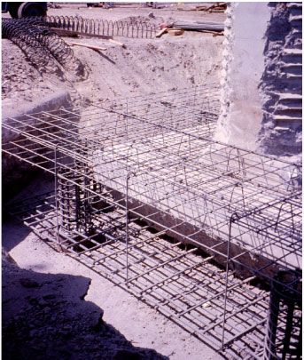
CALTRANS STRUCTURAL CONTROL FOR BRIDGES                                  451

                   Figure 1. Span drop o from support-seats that are too narrow.

                        Figure 2. Separation of deck thermal expansion joints.

Copyright ? 2005 John Wiley & Sons, Ltd.                Earthquake Engng Struct. Dyn. 2005; 34:449–470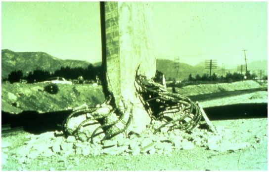
452                                        J. E. ROBERTS

                                Figure 3. Early hinge restrainer detail.

                              Figure 4. Improved hinge restrainer detail.

   Experience in subsequent earthquakes showed that the cables in this design were of insuf-
cient length to allow for some elastic performance and many of them merely failed as the
cables snapped. The hinge restrainer detail was improved after the Loma Prieta earthquake
of 1989 by extending the length to allow for some elastic movement and energy absorption
but still controlling the total joint opening shown in Figure 4.
   Another problem at deck hinge joints is caused by the combination of short columns in
the end spans, rigid diaphragm abutments, and the extreme skew which caused the decks
to rotate and come o the supporting end of the hinge. As the rotation was not considered
in the original restrainer design, and because drilling holes through and normal to the hinge
diaphragms of a highly skewed bridge is dicult, the restrainer cables were installed parallel

Copyright ? 2005 John Wiley & Sons, Ltd.                 Earthquake Engng Struct. Dyn. 2005; 34:449–470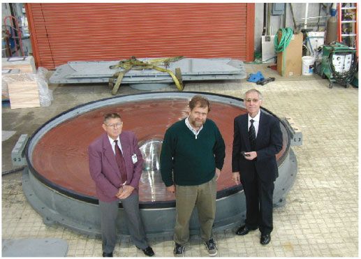
CALTRANS STRUCTURAL CONTROL FOR BRIDGES                                   453

                        Figure 5. Damage due to rotation at deck hinge joint.

                                    Figure 6. Hinge extender detail.

to the girder lines. Also, installing restrainers normal to the expansion joint of a skewed bridge
inhibits thermal movements. Since the hinge restrainer cables were not installed normal to the
hinge joint, they bent and rotated slightly and allowed the deck to come o the support,
and the cables failed due to unanticipated overload (Figure 5). In this detail today we use
steel pipe hinge extenders to keep the joint aligned. The hinge seat extender also is designed
to carry both vertical and horizontal loads due to seismic forces, therefore preventing the
supported portion of the bridge from dropping even if it slides o its bearing seat (Figure 6).
   Included in this phase of the retrot design was the installation of devices to fasten the
superstructure elements to the substructure in order to prevent those superstructure elements

Copyright ? 2005 John Wiley & Sons, Ltd.                 Earthquake Engng Struct. Dyn. 2005; 34:449–470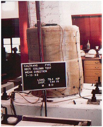
454                                         J. E. ROBERTS

                         Figure 7. Restrainer cables to prevent girder fall o.

                    Figure 8. Continuous bridge with no intermediate deck joints.

from falling o their supports. These joint restrainer details are very eective and, more
important, they are inexpensive to install relative to other seismic details. Figure 7 shows a
typical installation of these restrainer cables.

Fewer deck joints
With the computer technology available today it is possible to design new bridges with fewer
deck joints. This minimizes the maintenance problems associated with deck joints and also
eliminates the potential for failure during an earthquake. There are fewer joints to maintain
but the joints must have the capability to allow for much larger movements. The modular joint
seals currently being used have not been totally satisfactory. Figure 8 shows a reconstructed
bridge after the 1994 Northridge earthquake. There are no longer intermediate joints in the
deck, as compared with the replaced bridge. Joints are provided only at the abutments includ-
ing seat lengths that are designed to accommodate 2 m of movement during an earthquake.

Copyright ? 2005 John Wiley & Sons, Ltd.                 Earthquake Engng Struct. Dyn. 2005; 34:449–470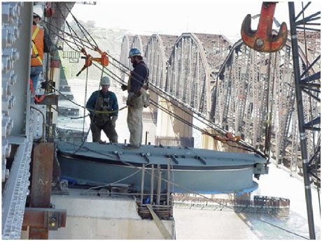
CALTRANS STRUCTURAL CONTROL FOR BRIDGES                                 455

                                Figure 9. Large movement deck joint.

Other bridges with tall columns have been designed with joints up to 700 m apart. The bridge
in Figure 9 has a deck joint that is designed to allow 2 m of longitudinal movement in an
earthquake.

Column and foundation design to control the location of plastic hinge zones
The most important structural control technology which has been developed in recent years
is the reinforcing steel detailing to control the location of the plastic hinge zone in bridge
superstructures and substructures. Figure 10 is a typical failure during the 1971 San Fernando
earthquake where the lack of adequate connement and joint shear reinforcement in the footing
contributed to the cause of the columns pulling out of the footings and collapsing.
   Investigation of damage at the Cypress Street Viaduct in Oakland, California, subsequent to
the 1989 Loma Prieta event revealed a deciency in many pre-1972 designed bridge footings.
Some of these footings suered joint shear failures, which caused structure settlement. These
footings were typically designed for vertical loads and only a 0:06g (60 gal) lateral force.
Investigation and research revealed a potential for failures due to lack of reinforcing steel in
the top of the footing to resist lateral moments. Analysis and laboratory tests did show a need
for a top mat of reinforcing steel in footings, which substantiated retrot details implemented
in designs prior to the Loma Prieta event. Figure 11 shows the damage pattern for footings
with no top mat. Figure 12 shows the retrotted footing reinforcement details.
   It is important to control the location of plastic hinge zones so they can be inspected quickly
after an earthquake without excavating the footings. It is also much easier to repair the zone
if it is above ground. It is California practice to locate the plastic hinge zone just below the
sot of the superstructure on multiple column bents with hinges at the top of the footing.
On single column bents the plastic hinge will form primarily at the base of the column for
transverse moments and both the top and bottom of the column for longitudinal moments.
Figure 13 illustrates the results of a seismic test for a bridge column. Note the plastic hinge
at the top of the column.

Copyright ? 2005 John Wiley & Sons, Ltd.               Earthquake Engng Struct. Dyn. 2005; 34:449–470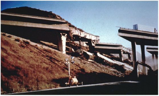
456                                        J. E. ROBERTS

                Figure 10. Pullout of column reinforcement—inadequate connement.

                           Figure 11. Footing=column model in testing lab.

Conservative shear key design
Shear keys are an important element of structural control which are dicult to inspect and
repair after an earthquake. On the other hand, they are a relatively inexpensive detail and
should be designed with much conservatism to prevent failure at intermediate expansion joints.

Copyright ? 2005 John Wiley & Sons, Ltd.               Earthquake Engng Struct. Dyn. 2005; 34:449–470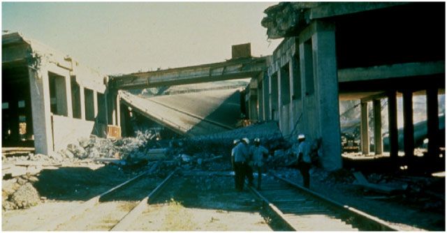
CALTRANS STRUCTURAL CONTROL FOR BRIDGES                                 457

            Figure 12. Additional reinforcing being added to existing column and footing.

                      Figure 13. Plastic hinge zone formation at top of column.

Copyright ? 2005 John Wiley & Sons, Ltd.               Earthquake Engng Struct. Dyn. 2005; 34:449–470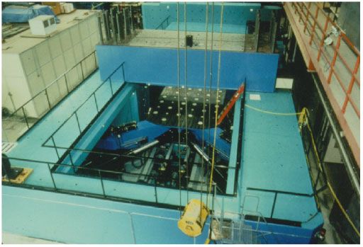
458                                        J. E. ROBERTS

                                     Figure 14. Failed shear keys.

In California the standard practice is to allow fusing at the abutments to reduce the numbers
of piles required. Figure 14 shows a failed shear key from the Bolu Viaduct after the 1999
Turkey earthquake. On this long viaduct nearly all the shear keys failed from what appears
to be a lack of reinforcing steel in the keys.

Pier rocking
This is a technique that has been applied on several bridges throughout the world. The most
famous example is the South Rangatikei River railroad bridge in New Zealand (Figure 15).
Vertical restrainer cables are used at the base of the columns or piers to control the rocking so
the structure will maintain equilibrium while it dissipates the energy imposed by the earthquake
motions. As the piers rock the superstructure is ghting its own dead weight which helps
dissipate energy. A related concept allows pile caps to rock or footings to rock on supporting
sub-grade.

Steel jackets and carbon shells for external connement
The second most important failure mode in recent earthquakes is the failure of bridge columns
due to inadequate horizontal or connement reinforcement as shown in Figure 16. The greatest
number of large-scale tests have been conducted to conrm the calculated ductile performance
of older, non-ductile bridge columns that have been strengthened by application of structural
steel plate, pre-stressed strand or epoxy-berglass and carbon ber composite jackets to pro-
vide the connement necessary to insure ductile performance. Since the Spring of 1987 the
researchers at UC San Diego have completed over 100 sets of tests on bridge column models.
   Work at the University of California at San Diego consisted of half-scale model testing of
the various single column bent retrot techniques. Theoretical calculations and research work
previously conducted in New Zealand by Dr Nigel Priestley showed that enclosing the columns
in steel casings could signicantly increase their shear strength and ductility by providing the
additional connement at the plastic hinge areas. A series of tests have been completed on
both round and rectangular columns with outstanding results. Both series of tests include
models of the prototype columns with the pre-1971 reinforcing details without retrotting,
retrotted columns using the steel shell connement and a post-damage retrotted column
using the steel shell to determine whether a non-retrotted damaged column can be salvaged

Copyright ? 2005 John Wiley & Sons, Ltd.                Earthquake Engng Struct. Dyn. 2005; 34:449–470
CALTRANS STRUCTURAL CONTROL FOR BRIDGES 459
Figure 15. Rangatikei River rocking bridge.
Figure 16. Column shear failure.
Copyright ? 2005 John Wiley & Sons, Ltd. Earthquake Engng Struct. Dyn. 2005; 34:449–470460 J. E. ROBERTS
Figure 17. Test of steel jacket in laboratory.
after an earthquake. Tests have also been completed on epoxy impregnated berglass fabric
connement, using both wet sheets applied at the site and pre-molded epoxy-berglass shells
which are produced in a plant, heat cured, and delivered to the site for installation. Carbon
ber lament wrapping techniques have also been tested and approved for eld installation.
Typical displacement ductility factors on retrotted undamaged columns of 6 to 8 have been
achieved. Achieved ductility factors have been limited by the test equipment in many cases.
We feel that ductility factors of 10 can be achieved without signicant force reduction. On
the post-damage retrotted column ductility factors of 2 to 4 were achieved; this would allow
post-seismic event repair, with moderate risk. Even though displacement ductility factors of
6 to 8 have been common in these rst tests, our analysis strategy is based on limiting
moment and displacement ductility demand to no greater than 4. Figure 17 is an example
of the column testing. Figure 18 is a typical eld installation of a steel jacket. Figure 19 is
an example of laboratory tests of composite jackets. Figure 20 is the eld installation of a
carbon ber jacket. Figure 21 is a completed eld installation of a carbon ber jacket.
Seismic isolation silos
On longer bridges which have variable column heights there have been several failures because
the shorter and stier columns close to the abutments attract most of the seismic force and fail.
Figure 22 is an example of that type of failure during the Northridge, California Earthquake
Copyright ? 2005 John Wiley & Sons, Ltd. Earthquake Engng Struct. Dyn. 2005; 34:449–470CALTRANS STRUCTURAL CONTROL FOR BRIDGES 461
Figure 18. Typical eld installation of steel jacket.
Figure 19. Test of composite jacket.
Copyright ? 2005 John Wiley & Sons, Ltd. Earthquake Engng Struct. Dyn. 2005; 34:449–470462 J. E. ROBERTS
Figure 20. Machine wrapping of composite jacket.
Figure 21. Completed carbon ber jacket eld installation.
Copyright ? 2005 John Wiley & Sons, Ltd. Earthquake Engng Struct. Dyn. 2005; 34:449–470CALTRANS STRUCTURAL CONTROL FOR BRIDGES 463
Figure 22. Collapse due to short column failure near abutment.
Figure 23. Seismic isolation silo.
of 17 January 1994. The short column under the bridge below the car in the foreground failed
and caused this collapse.
A solution to this problem is the seismic isolation silo, a steel shell which provides an
annular space around the column and extends the necessary depth (from 3 to 15 m) below
ground to extend the elastic length of the shorter columns. This detail can make all columns
in the same frame of nearly equal length and stiness so they all share equally in resisting
lateral forces. This detail is shown in Figure 23.
Shock transmission lock-up devices and viscous dampers
Shock transmission lock-up devices are used on large bridges to provide for thermal expansion
and contraction but are designed to lock-up during a seismic event. Provision for dissipating
Copyright ? 2005 John Wiley & Sons, Ltd. Earthquake Engng Struct. Dyn. 2005; 34:449–470464 J. E. ROBERTS
Figure 24. Shock transmission lock-up device.
Figure 25. Shock transmission lock-up device in place.
the seismic forces is provided by other devices and yielding structural members. The shock
transmission devices are designed with small orices so the uids cannot ow rapidly and
thus the devices lock up and transmit the seismic shock waves to other parts of the structure.
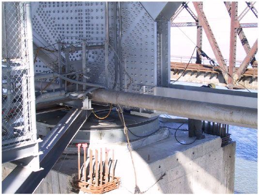
Figure 24 is a close-up of a typical large shock transmission lock-up device. Figure 25 is a
view of the unit in place on the lower cord of a large steel truss on the Carquinez bridge in
Northern California.
Various types of viscous dampers have been used on the Terminal Island Suspension Bridge
in the Los Angeles harbor and on the San Francisco–Oakland Bay Bridge. These dampers are
designed to absorb energy and assist in resisting seismic forces. Figure 26 is a typical viscous
damper on a box girder freeway bridge.
Copyright ? 2005 John Wiley & Sons, Ltd. Earthquake Engng Struct. Dyn. 2005; 34:449–470CALTRANS STRUCTURAL CONTROL FOR BRIDGES 465
Figure 26. Viscous damper in place.
Figure 27. Rubber–lead core seismic isolation bearing.
Rubber–lead core isolation bearings
These devices have been used on many bridges with short or medium spans, requiring reason-
ably small displacements during an earthquake. The devices are made up of alternating layers
of neoprene or natural rubber and thin steel plates and contain a 100 to 150 mm diameter
lead core. During seismic activity the pad is designed to displace up to 100% of its rub-
ber thickness without failure. The lead core heats up and dissipates energy during the event.
Figure 27 is an example of a rubber–lead core seismic isolation bearing. Many of these
have been used to replace the older rocker bearings in seismic retrot programs.
Copyright ? 2005 John Wiley & Sons, Ltd. Earthquake Engng Struct. Dyn. 2005; 34:449–470466 J. E. ROBERTS
Figure 28. Benicia–Martinez Bridge. The largest inverted pendulum bearings are installed on this
bridge, which is on a lifeline route.
Figure 29. Large testing machine for seismic isolation bearings.
Inverted pendulum isolation bearings
Inverted pendulum bearings have been used extensively to isolate large buildings from the
foundations and reduce the seismic forces that will be applied to the main building elements.
Copyright ? 2005 John Wiley & Sons, Ltd. Earthquake Engng Struct. Dyn. 2005; 34:449–470CALTRANS STRUCTURAL CONTROL FOR BRIDGES 467
Figure 30. Large diameter bearing after test.
Several manufacturers produce these bearings and a couple of University researchers have
developed testing facilities to test the bearings. Most of these bearings are around 3 feet in
diameter and must sustain vertical loads and displacements far smaller than what is required
for a long-span bridge. For large trusses on long-span bridges it has been necessary to develop
super-large inverted pendulum isolation bearings in order to accommodate the vertical dead
loads and large movements during an earthquake. There are only four locations where the
bearings can be placed on these trusses, one at each corner of the span. They are being used
on the Benicia–Martinez, San Diego–Coronado, and San Francisco–Oakland Bay Bridges in
California and the I-40 Mississippi River Bridge at Memphis, Tennessee. Figure 28 shows the
Benicia–Martinez Bridge in Northern California, which carries I-680 over the Carquinez straits.
The spans have all been isolated from the substructure by large inverted pendulum bearings
from 4 feet to 12 feet in diameter. These bearings are so large that a new testing machine
had to be constructed at UC San Diego to handle the 6000 ton vertical loads, allow for up to
44 inches of lateral movement in each direction, and be able to sustain the seismic motions
for 60 s. This required a reservoir capacity of 5000 gallons under 5000 psi hydraulic pressure.
Figure 29 is an overview of the testing machine. All prototype bearings were tested before
the nal design was approved. Each bearing was also proof tested prior to installation on
the bridge. Current specications also require that a sample bearing be removed from service
after each 5 year period to test for environmental degradation. This is done by retaining a
spare bearing to install on the bridge and retesting the bearing that has been in the bridge
under the environmental exposure at the site. Figure 30 shows one of the large bearings after
removal from the testing machine. Figures 31 to 34 illustrate the eld installation of the
largest inverted pendulum bearing; it is 12 feet in diameter.
Copyright ? 2005 John Wiley & Sons, Ltd. Earthquake Engng Struct. Dyn. 2005; 34:449–470468 J. E. ROBERTS
Figure 31. The 12 foot diameter bearings on barge.
Figure 32. Bearing being hoisted into place.
Copyright ? 2005 John Wiley & Sons, Ltd. Earthquake Engng Struct. Dyn. 2005; 34:449–470CALTRANS STRUCTURAL CONTROL FOR BRIDGES 469
Figure 33. Bearing being moved laterally into place.
Figure 34. The 12 foot bearing in nal position.
Copyright ? 2005 John Wiley & Sons, Ltd. Earthquake Engng Struct. Dyn. 2005; 34:449–470470 J. E. ROBERTS
CONCLUSION
The use of various structural control strategies during the design stage has been a major
element in the seismic retrot strengthening of over 2200 bridges on the California state
highway system. In addition, more than 500 local city and county bridges have been retrotted
using many of the same strategies and details. It has been estimated that most of these state
and local bridges have been retrot strengthened for between 10% and 20% of replacement
cost, providing a tremendous saving to the taxpayers. For the major structures in the San
Francisco Bay, the Los Angeles Harbor and San Diego Bay the retrot costs have been
substantially greater because of the deep water foundations and bay mud layers. These costs
have ranged from 50% to 100% of replacement cost. Caltrans adopted a policy in the retrot
program to consider replacement rather than retrot when costs of retrot exceeded 50% of
replacement cost. The process for prioritizing bridges for retrot is too complex to discuss at
length in this paper. It involves consideration of 18 variable factors including site, trac, age,
soil conditions, which were included in an algorithm for prioritizing. The most critical bridges
in this process were retrotted rst. Most of these structural control strategies were executed
while trac continued to use the system. Although good laboratory test results give us great
optimism for excellent performance in a major earthquake, these strategies were eld tested
in the Northridge earthquake of 1994, generally with excellent results. Calculated demands
are based on assumed ground motions, which may or may not be close to reality. There
are still broad dierences of opinion regarding magnitude and application of vertical ground
accelerations.
California has also implemented an aggressive seismic monitoring system to record and
evaluate the performance of these bridges during future earthquakes. Over 100 bridges have
been instrumented through the Division of Mines and Geology’s ‘Strong Motion Instrumen-
tation Program’ and many of the latest installations are remotely monitored.
Copyright ? 2005 John Wiley & Sons, Ltd. Earthquake Engng Struct. Dyn. 2005; 34:449–470You can also read