Digital Voice Interface Application Note
←
→
Page content transcription
If your browser does not render page correctly, please read the page content below
Digital Voice Interface
      Application Note
                 80000NT11246A
              Rev. 9 – 2021-01-27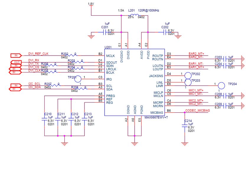
80000NT11246A - Digital Voice Interface                                           Introduction
                                                                                        Scope

SPECIFICATIONS ARE SUBJECT TO CHANGE WITHOUT NOTICE

NOTICE
While reasonable efforts have been made to assure the accuracy of this document, Telit
assumes no liability resulting from any inaccuracies or omissions in this document, or from
use of the information obtained herein. The information in this document has been carefully
checked and is believed to be reliable. However, no responsibility is assumed for
inaccuracies or omissions. Telit reserves the right to make changes to any products
described herein and reserves the right to revise this document and to make changes from
time to time in content hereof with no obligation to notify any person of revisions or changes.
Telit does not assume any liability arising out of the application or use of any product,
software, or circuit described herein; neither does it convey license under its patent rights
or the rights of others.
It is possible that this publication may contain references to, or information about Telit
products (machines and programs), programming, or services that are not announced in
your country. Such references or information must not be construed to mean that Telit
intends to announce such Telit products, programming, or services in your country.

COPYRIGHTS
This instruction manual and the Telit products described in this instruction manual may be,
include or describe copyrighted Telit material, such as computer programs stored in
semiconductor memories or other media. Laws in the Italy and other countries preserve for
Telit and its licensors certain exclusive rights for copyrighted material, including the
exclusive right to copy, reproduce in any form, distribute and make derivative works of the
copyrighted material. Accordingly, any copyrighted material of Telit and its licensors
contained herein or in the Telit products described in this instruction manual may not be
copied, reproduced, distributed, merged or modified in any manner without the express
written permission of Telit. Furthermore, the purchase of Telit products shall not be deemed
to grant either directly or by implication, estoppel, or otherwise, any license under the
copyrights, patents or patent applications of Telit, as arises by operation of law in the sale
of a product.

COMPUTER SOFTWARE COPYRIGHTS
The Telit and 3rd Party supplied Software (SW) products described in this instruction
manual may include copyrighted Telit and other 3rd Party supplied computer programs
stored in semiconductor memories or other media. Laws in the Italy and other countries
preserve for Telit and other 3rd Party supplied SW certain exclusive rights for copyrighted
computer programs, including the exclusive right to copy or reproduce in any form the
copyrighted computer program. Accordingly, any copyrighted Telit or other 3rd Party
supplied SW computer programs contained in the Telit products described in this instruction
manual may not be copied (reverse engineered) or reproduced in any manner without the
express written permission of Telit or the 3rd Party SW supplier. Furthermore, the purchase
of Telit products shall not be deemed to grant either directly or by implication, estoppel, or
otherwise, any license under the copyrights, patents or patent applications of Telit or other
3rd Party supplied SW, except for the normal non-exclusive, royalty free license to use that
arises by operation of law in the sale of a product.

Rev. 9                                    Page 2 of 34                            2021-01-27
80000NT11246A - Digital Voice Interface                                           Introduction
                                                                                        Scope

USAGE AND DISCLOSURE RESTRICTIONS
I. License Agreements
The software described in this document is the property of Telit and its licensors. It is
furnished by express license agreement only and may be used only in accordance with the
terms of such an agreement.

II. Copyrighted Materials
Software and documentation are copyrighted materials. Making unauthorized copies is
prohibited by law. No part of the software or documentation may be reproduced,
transmitted, transcribed, stored in a retrieval system, or translated into any language or
computer language, in any form or by any means, without prior written permission of Telit

III. High Risk Materials
Components, units, or third-party products used in the product described herein are NOT
fault-tolerant and are NOT designed, manufactured, or intended for use as on-line control
equipment in the following hazardous environments requiring fail-safe controls: the
operation of Nuclear Facilities, Aircraft Navigation or Aircraft Communication Systems, Air
Traffic Control, Life Support, or Weapons Systems (High Risk Activities"). Telit and its
supplier(s) specifically disclaim any expressed or implied warranty of fitness for such High
Risk Activities.

IV. Trademarks
TELIT and the Stylized T Logo are registered in Trademark Office. All other product or
service names are the property of their respective owners.

V. Third Party Rights
The software may include Third Party Right software. In this case you agree to comply with
all terms and conditions imposed on you in respect of such separate software. In addition
to Third Party Terms, the disclaimer of warranty and limitation of liability provisions in this
License shall apply to the Third Party Right software.
TELIT HEREBY DISCLAIMS ANY AND ALL WARRANTIES EXPRESS OR IMPLIED
FROM ANY THIRD PARTIES REGARDING ANY SEPARATE FILES, ANY THIRD PARTY
MATERIALS INCLUDED IN THE SOFTWARE, ANY THIRD PARTY MATERIALS FROM
WHICH THE SOFTWARE IS DERIVED (COLLECTIVELY “OTHER CODE”), AND THE
USE OF ANY OR ALL THE OTHER CODE IN CONNECTION WITH THE SOFTWARE,
INCLUDING (WITHOUT LIMITATION) ANY WARRANTIES OF SATISFACTORY
QUALITY OR FITNESS FOR A PARTICULAR PURPOSE.
NO THIRD PARTY LICENSORS OF OTHER CODE SHALL HAVE ANY LIABILITY FOR
ANY DIRECT, INDIRECT, INCIDENTAL, SPECIAL, EXEMPLARY, OR CONSEQUENTIAL
DAMAGES (INCLUDING WITHOUT LIMITATION LOST PROFITS), HOWEVER CAUSED
AND WHETHER MADE UNDER CONTRACT, TORT OR OTHER LEGAL THEORY,
ARISING IN ANY WAY OUT OF THE USE OR DISTRIBUTION OF THE OTHER CODE
OR THE EXERCISE OF ANY RIGHTS GRANTED UNDER EITHER OR BOTH THIS
LICENSE AND THE LEGAL TERMS APPLICABLE TO ANY SEPARATE FILES, EVEN IF
ADVISED OF THE POSSIBILITY OF SUCH DAMAGES.
Rev. 9                                    Page 3 of 34                            2021-01-27
80000NT11246A - Digital Voice Interface Introduction
Scope
APPLICABILITY TABLE
This documentation applies to the following product families:
Table 1: Applicability Table
Module Name Description
LE910-EU
LE910-NA
LE910-NV
LE920-EU
LE920-NA
LE920-CN
LE920A4-EU
LE920A4-NA
LE920A4-CN
LE940A6-NA
LE940A9-CN
LE910C1-NA North America – AT&T with global roaming
LE910C1-NS North America - Sprint variant
LE910C1-AP APAC variant CAT1 variant
LE910C4-AP APAC variant CAT4 variant
LE910C4-EU Europe CAT4 variant
LE910C1-EU Europe CAT1 variant
LE910C1-EUX Europe CAT1 variant
LE910C4-NF North America CAT4 variant
LE910C1-NF North America CAT1 variant
LE910C1-SA North America CAT1 variant – AT&T
LE910C1-SAX North America CAT1 variant – AT&T
LE910C1-ST North America CAT1 variant – T Mobile
Rev. 9 Page 4 of 34 2021-01-2780000NT11246A - Digital Voice Interface Introduction
Scope
Module Name Description
LE910C1-SV North America CAT1 variant – Verizon
LE910C1-SVX North America CAT1 variant – Verizon
LE910C1-LA Latin America CAT1 variant
LE910C4-LA Latin America CAT4 variant
LE910C4-CN China CAT4 variant
LE910CX-WWX World Wide CATX variant
The features described by the present document are provided by the products equipped
with the software versions equal or higher than the versions shown in the table.
NOTE:
Information – ‘X’ means ThreadX OS in LE910C1-EUX, LE910C1-SAX,
LE910C1-SVX and LE910CX-WWX. The other models which don’t have ‘X’
letter are Linux OS.
Rev. 9 Page 5 of 34 2021-01-2780000NT11246A - Digital Voice Interface Introduction
Scope
CONTENTS
1. INTRODUCTION .............................................................................................8
Scope ............................................................................................................. 8
Audience......................................................................................................... 8
Contact Information, Support .......................................................................... 8
Text Conventions ............................................................................................ 9
Related Documents .......................................................................................10
Document Organization .................................................................................10
Abbreviations and Acronyms .........................................................................11
2. DIGITAL VOICE INTERFACE USE ...............................................................12
DVI Introduction .............................................................................................13
3. TIMING CHARACTERISTICS .......................................................................21
4. DVI SETTING ................................................................................................23
5. ANNEX ..........................................................................................................29
I2S Overview ..................................................................................................29
I2S Timing Characteristics ..............................................................................30
LE910Cx I2S characteristics ..........................................................................32
Schematic ......................................................................................................32
6. REVISION HISTORY .....................................................................................33
Rev. 9 Page 6 of 34 2021-01-2780000NT11246A - Digital Voice Interface Introduction
Scope
TABLE OF FIGURES
Figure 1 Example of Digital Voice Interface Use ............................................................. 12
Figure 2 DVI signals........................................................................................................ 14
Figure 3 Primary PCM_SYNC timing (Short sync, 2048kHz clock) ................................. 21
Figure 4 External codec to LE910 timing ......................................................................... 22
Figure 5 LE910 to External codec timing ......................................................................... 22
Figure 6 Telit Module/Codec Connections ...................................................................... 23
Figure 7 I2S bus configurations....................................................................................... 29
Figure 8 High-level I2S timing ......................................................................................... 31
Figure 9 I2S timing details Tx & Rx ................................................................................. 31
Figure 10 Schematic for Reference Design ..................................................................... 32
Rev. 9 Page 7 of 34 2021-01-2780000NT11246A - Digital Voice Interface Introduction
Scope
1. Introduction
Scope
The present document provides the reader with a guideline concerning the setting and
use of the Digital Voice Interface developed on the Telit’s modules families shown in the
Applicability Table.
Audience
The document is intended for those users that need to develop applications dealing with
signal voice in digital format.
Contact Information, Support
For general contact, technical support services, technical questions and report
documentation errors, contact Telit Technical Support at:
• TS-EMEA@telit.com
• TS-AMERICAS@telit.com
• TS-APAC@telit.com
• TS-SRD@telit.com
Alternatively, use:
http://www.telit.com/support
For detailed information about where you can buy the Telit modules or for
recommendations on accessories and components visit:
http://www.telit.com
Our aim is to make this guide as helpful as possible. Keep us informed of your comments
and suggestions for improvements.
Telit appreciates feedback from the users of our information.
Rev. 9 Page 8 of 34 2021-01-2780000NT11246A - Digital Voice Interface Introduction
Text Conventions
Text Conventions
DANGER:
Danger – This information MUST be followed or catastrophic equipment
failure or bodily injury may occur.
WARNING:
Caution or Warning – Alerts the user to important points about integrating the
module, if these points are not followed, the module and end user equipment
may fail or malfunction.
NOTE:
Tip or Information – Provides advice and suggestions that may be useful
when integrating the module.
All dates are in ISO 8601 format, i.e. YYYY-MM-DD.
Rev. 9 Page 9 of 34 2021-01-2780000NT11246A - Digital Voice Interface Introduction
Related Documents
Related Documents
Table 2: Related Documents
Document Title Document Number
LE910 Hardware User Guide 1vv0301089
MAX9867 Ultra-Low Power Stereo Audio Codec, MAXIM
LE910 AT Commands Reference Guide 80421ST10585A
LE920 Hardware User Guide 1vv0301026
LE920 AT Commands Reference Guide 80407ST10116A
LE920A4 Hardware User Guide 1vv0301261
LE910Cx Hardware User Guide 1VV0301298
LE940A6/A9 Hardware User Guide 1VV0301367
Document Organization
Chapter 1: “Introduction” provides a scope for this document, target audience, contact and
support information, and text conventions.
Chapter 2: “Overview” provides an overview of the document.
Chapter 3: “Module’s DVI (PCM)” describes the DVI port
Chapter 4: “Protocol description”
Chapter 5: “Parameters and timing characteristics”
Chapter 6: “Custom AT commands”
Chapter 7: “External codec” provides an example of interfacing with an external audio
codec.
Rev. 9 Page 10 of 34 2021-01-2780000NT11246A - Digital Voice Interface Introduction
Abbreviations and Acronyms
Abbreviations and Acronyms
DTE Data Terminal Equipment
DVI Digital Voice Interface
GPIO General Purpose Input/Output
I2C Inter-Integrated Circuit
I2S Inter-IC Sound
MSB Most Significant Bit
Rev. 9 Page 11 of 34 2021-01-2780000NT11246A - Digital Voice Interface Digital Voice Interface Use
Abbreviations and Acronyms
2. Digital Voice Interface Use
Before dealing with the configuration and technical aspects of the Telit’ Digital Voice
Interface (DVI) it is useful to illustrate briefly where and how this interface can be used,
refer to Figure 1.
The voice coming from the downlink, in digital format, is captured by the dedicated
software running on the Telit’s module and directed to the Digital Voice Interface. The
Audio Codec decodes the voice and sends it to the speaker. The other way round the
voice captured by the microphone is coded by the Audio Codec and directed through the
Digital Voice Interface to the module that collects the received voice, in digital format, and
sends it on the uplink.
The DVI uses the PCM or I2S interface as part of the audio front end.
Uplink
Digital Voice Interface
Downlink
Telit
Audio Codec
Module
Figure 1 Example of Digital Voice Interface Use
NOTE:
LE910C1-EUX, LE910C1-SAX, LE910C1-SVX and LE910CX-WWX
Supported I2S standard only.
PCM not supported.
Rev. 9 Page 12 of 34 2021-01-2780000NT11246A - Digital Voice Interface Digital Voice Interface Use
DVI Introduction
DVI Introduction
Although analog communication is ideal for human communication, analog transmission is
neither robust nor efficient at recovering from line noise.
As example in the early telephony network, when analog transmission was passed
through amplifiers to boost the signal, not only was the voice boosted but the line noise
was amplified, as well. This line noise resulted in an often-unusable connection.
It is much easier for digital samples, which are comprised of 1 and 0 bits, in order to be
separated from line noise. Therefore, when analog signals are regenerated as digital
samples, a clean sound is maintained.
PCM converts analog sounds into digital form by sampling the analog sounds 8000 times
per second and converting each sample into a numeric code. If you sample an analog
signal at twice the rate of the highest frequency of interest, you can accurately reconstruct
that signal back into its analog form (Nyquist theorem). Because most speech content is
below 4000Hz, a sampling rate of 8000 times per second (8 KHz that means 125 µSec
between samples) is required.
The physical DVI interface provided by the Telit’s modules is based on the I2S Bus. An
overview of the standard I2S Bus is described in chapter 5.1. Table. 1 summarizes the
DVI signals and a short description for each one of them: refer to documents [1] and [4] to
have information on electrical characteristics and signals pin-out in accordance with the
used module.
DVI Signal DVI Signal name Description
Clock DVI_CLK Data Clock
Word Alignment DVI_WAO Frame Synchronism
serial audio data input DVI_RX Received Data
serial audio data output DVI_TX Transmitted Data
Table. 1: DVI Signals
Rev. 9 Page 13 of 34 2021-01-2780000NT11246A - Digital Voice Interface Digital Voice Interface Use
DVI Introduction
The LE910Cx Linux OS variants support both MASTER and SLAVE Mode.
LE910C1-EUX,LE910C1-SAX,LE910C1-SVX,LE910CX-WWX and other models support
MASTER Molde only.
The figures below show the configuration of the DVI interface relating to the Word
Alignment and Clock signals. When the module is Master the Clock and Word Alignment
signals (also called Word Alignment Output WAO) are generated by the module itself.
Clock
Audio
Word Alignment
Telit Device
data input
Module Codec
data output
Module = Master
Figure 2 DVI signals
Rev. 9 Page 14 of 34 2021-01-2780000NT11246A - Digital Voice Interface Digital Voice Interface Use
DVI Introduction
DVI Configurations
The command AT#ADSPC is usable to configure the DSP profile according to the device
connected to Codec.
LE910C1-EUX,LE910C1-SAX,LE910C1-SVX and LE910CX-WWX does not support
AT#ADSPC.
#ADSPC - Audio DSP Configuration
AT#ADSPC= Set command switches the DSP profile audio path depending on
[,] parameter
Parameter:
- DSP profile configuration
0. Automatic (factory default)
1. Hands Free
2. Headset
3. Handset
4. Speaker phone Bluetooth
5. TTY
6. USB
< ecns mode >
0. Disables ECNS mode (default)
1. Enables ECNS.
Note:
• On Automatic mode:
Digital: handset
Analog: according to #CAP
• This command influence on the #CAP/ #SRP.
• On Active/MT/MO Voice Call return Error.
• When #TTY command enabled, SET #ADSPC command return
Error.
• The = 5 "TTY" only configured DSP profile to "Full TTY" mode,
to enable TTY mode and another TTY mode using by #TTY
command.
• The = 6 is only supported by “Disable ECNS mode”
AT#ADSPC? Read command reports the active DSP profile configuration in the format:
For TTY profile:
#ADSPC:
For Another DSP profile:
#ADSPC: , < ecns mode >.
AT#ADSPC=? Test command reports the supported values for the parameter .
The command AT#DVICFG is usable to configure the DVI interface.
LE910C1-EUX,LE910C1-SAX,LE910C1-SVX and LE910CX-WWX does not support
AT#DVICFG.
Its syntax is the following:
Rev. 9 Page 15 of 34 2021-01-2780000NT11246A - Digital Voice Interface Digital Voice Interface Use
DVI Introduction
#DVICFG – DVI CONFIGURATION
AT#DVICFG=[ Set command sets the DVI configuration
[,[,[, : Clock speed for master mode
[,]]]]]
: PCM padding enable in decoder path
0 : disable
1 : enable(factory default)
: PCM format in decoder path
0 : u-Law
1 : A-Law
2 : linear(factory default)
: PCM padding enable in encoder path
0 : disable
1 : enable(factory default)
: PCM format in encoder path
0 : u-Law
1 : A-Law
2 : linear(factory default)
Note:
• #DVICFG parameters are saved in the extended profile.
• #DVICFG return Error, when #DVICLK enabled.
• LE910x, LE920x supports only the first parameter
Normal mode (factory default) = 2048KHz with sample rate 8k.
High speed mode = 4096 KHz with sample rate 16k.
• Another parameters (,,,)have no effect and are included only for backward
compatibility.
• The command work only for PCM mode(#DVIEXT=0)
• #DVICFG return Error, when I2S mode(#DVIEXT=1)
AT#DVICFG=? Test command returns the supported range of values of parameter ,
,,,.
Rev. 9 Page 16 of 34 2021-01-2780000NT11246A - Digital Voice Interface Digital Voice Interface Use
DVI Introduction
The AT#DVI command enables/disables the DVI interface.
Its syntax is the following:
#DVI - Digital Voiceband Interface
AT#DVI= Set command enables/disables the Digital Voiceband Interface.
[,,
] Parameters:
- enables/disables the DVI.
0 – DVI disabled; (factory default)
1 – DVI enabled;
2 - DVI port 2 (factory default)
0 - DVI slave
1 - DVI master (factory default)
2 - DVI master, clock always on
Note:
• #DVI parameters are saved in the extended profile.
• 2 is not saved in the extended profile.
Only 0 or 1 can be saved in the extended profile.
• #DVI parameters are not saved in the extended profile by LE910C1-
EUX /SAX/SVX and LE910Cx-WWX product.
• On 0 supported by “DVI master” only.
• When the 2, If change the 2 to
0 or 1 the device will reboot for clock off.
• #DVICFG and #DVICLK return Error, when 2.
If you want to set the DVI clock in 2, Please set
2 after set the DVI clock in 0 or 1.
If you want to set the DVI clock in 2, Please set
2 after set the DVI clock in 0 or 1.
• It impact power consumption if using 2.
• The parameter have no effect and is included only for
backward compatibility.
• On Active/MT/MO Voice Call return Error.
• 0 and 2 are not supported by LE910C1-EUX/SAX/SVX
and LE910Cx-WWX product.
• LE910C1-EUX /SAX/SVX and LE910Cx-WWX product only supports
I2S interface.
AT#DVI? Read command reports last setting, in the format:
#DVI: ,,
AT#DVI=? Test command reports the range of supported values for parameters
, and
Example AT#DVI=1,2,1
OK
DVI activated for audio. DVI is configured as master providing on DVI Port #2
Rev. 9 Page 17 of 34 2021-01-2780000NT11246A - Digital Voice Interface Digital Voice Interface Use
DVI Introduction
The LE910x Linux OS modules have the following possible configurations:
Normal mode (factory default)
• Master Mode
• 8KHz
• 16 bits
• 2.048MHz clock
High Speed mode
• Master Mode
• 16KHz
• 16 bits
• 4.096MHz clock
The LE920x Linux OS modules have the following possible configurations:
Normal mode (factory default)
• Master Mode
• 8KHz
• 16 bits
• 2.048MHz clock
High Speed mode
• Master Mode
• 16KHz
• 16 bits
• 4.096MHz clock
#DVICLK - Digital Voiceband Interface Extension
AT#DVICLK=[,] Voiceband Interface
Parameters:
0– Disable (factory default)
128 – DVI Clock activated at 128KHz
256 – DVI Clock activated at 256KHz
512 – DVI Clock activated at 512KHz
1024 – DVI Clock activated at 1024KHz
2048 – DVI Clock activated at 2048KHz
4096 – DVI Clock activated at 4096KHz
0 - audio scheduler sample rate 8KHz (factory default)
1 - audio scheduler sample rate 16KHz
Note :
• On Active/MT/MO Voice Call return Error.
• Clock 4096KHz don't supported with Sample Rate 8KHz
• #DVICFG return Error, when enabled.
Rev. 9 Page 18 of 34 2021-01-2780000NT11246A - Digital Voice Interface Digital Voice Interface Use
DVI Introduction
#DVICLK - Digital Voiceband Interface Extension
• On Clock value zero (0) the clock rate and sample rate taken from
#DVICFG value.
• This parameter is saved in NVM issuing AT&W command.
• The command work only for PCM mode (#DVIEXT=0)
• #DVICLK return Error, when I2S mode (#DVIEXT=1)
• #DVICLK return Error, when clock always on mode (#DVI=1,2,2)
• For LE910C1-EUX /SAX/SVX and LE910Cx-WWX product:
• Clock 256KHz supports only Sample Rate 8KHz.
• Clock 512KHz supports only Sample Rate 16KHz.
• Both and should be entered.
#DVICLK return Error, if only is enter.
• Factory default is 256 and 0(8KHz).
• Not support #DVICFG.
• Not supports 0, 128, 1024, 2048,
4096.
• This parameter is not save in NVM.
AT#DVICLK? Read command reports last setting, in the format:
#DVICLK:< clock > ,
AT#DVICLK =? Test command returns the range of supported values for all the sub parameters.
The command AT#DVIEXT is usable to configure the Extended DVI interface.
LE910C1-EUX,LE910C1-SAX,LE910C1-SVX and LE910CX-WWX does not support
AT#DVIEXT.
Its syntax is the following:
#DVIEXT – Extended Digital Voiceband Interface
AT#DVIEXT=[,[,[,[,]]]]
0 – PCM Mode (factory default)
1 – I2S Mode
0 – audio scheduler sample rate 8KHz (factory default)
1 – audio scheduler sample rate 16KHz
2 – audio scheduler sample rate 48KHz
0 – samplewidth has no effect is included only for backward compatibility.
0 – audiomode has no effect is included only for backward compatibility.
0 – edge has no effect is included only for backward compatibility.
Rev. 9 Page 19 of 34 2021-01-2780000NT11246A - Digital Voice Interface Digital Voice Interface Use
DVI Introduction
#DVIEXT – Extended Digital Voiceband Interface
Note: Sample width has to be only in I2S Mode.
Note: Manual reboot is required after changing.
Note: The setting is saved in system.
Note: Supported samplewidth is 16bit only.
AT#DVIEXT? Read command reports last setting, in the format:
#DVIEXT: ,,< samplewidth>,,
AT#DVIEXT=? Test command reports the supported range of values for the parameters
,,< samplewidth>, ,
Rev. 9 Page 20 of 34 2021-01-2780000NT11246A - Digital Voice Interface Timing Characteristics
DVI Introduction
3. Timing Characteristics
Parameter Description Min Typical Max Units
t(sync) PCM_SYNC cycle time - 125 - us
t(syncha) PCM_SYNC asserted time - 488 - ns
t(syncd) PCM_SYNC de-asserted time - 124.5 - us
t(clk) PCM_CLOCK cycle time - 488 - ns
t(clkh) PCM_CLOCK high time - 244 - ns
t(clkl) PCM_CLOCK low time - 244 - ns
t(sync_offset) PCM_SYNC offset time to PCM_CLOCK falling - 122 - ns
t(sudin) PCM_RX setup time to PCM_CLOCK falling 60 - - ns
t(hdin) PCM_RX hold time after PCM_CLOCK falling 60 - - ns
Delay from PCM_CLOCK rising to PCM_TX
t(pdout) - - 60 ns
valid
Delay from PCM_CLOCK falling to PCM_TX
t(zdout) - - 60 ns
HIGH-Z
t(sync)
PCM_SYNC
t(synca) t(syncd)
Figure 3 Primary PCM_SYNC timing (Short sync, 2048kHz clock)
Rev. 9 Page 21 of 34 2021-01-2780000NT11246A - Digital Voice Interface Timing Characteristics
DVI Introduction
t(clk)
PCM_CLOCK
t(clkh) t(clkl)
t(susync)
t(hsync)
PCM_SYNC
t(sudin) t(hdin)
PCM_RX MSB LSB
Figure 4 External codec to LE910 timing
t(clk)
PCM_CLOCK
t(clkh) t(clkl)
t(susync)
t(hsync)
PCM_SYNC
t(pdout) t(pdout) t(zdout)
PCM_TX MSB LSB
Figure 5 LE910 to External codec timing
Rev. 9 Page 22 of 34 2021-01-2780000NT11246A - Digital Voice Interface DVI Setting
DVI Introduction
4. DVI Setting
The next chapters show how to configure an external codec connected to the Module.
All the following setting examples are performed using the hardware configuration shown
in Figure 6.
I2C bus is used to configure the MAX9867 Codec1 [2].
The DVI bus provides the voice connection between the two devices.
I2C bus
SDA SCL
User DTE
Clock
System CLK
Word Alignment
Telit MAX9867
Module data input
Codec
data output
DVI bus based on
I2S bus
Figure 6 Telit Module/Codec Connections
NOTE: The CODEC Example is applicable only to the High Speed mode
• Master Mode
• 16KHz
• 16 bits
• 4.096 MHz clock
NOTE: Chapter "4. DVI Setting" is an example only for the PCM interface
of the Linux OS module.
1 The following examples use the MAX9867 Codec, see chapter 5.4 for a schematic reference
design. In general, the user can use any codec compliant with the technical requirements of the
Telit’s modules.
Rev. 9 Page 23 of 34 2021-01-2780000NT11246A - Digital Voice Interface DVI Setting
DVI Introduction
The module has the role of master. In this case, the WAO and CLK signals are generated
by the module. The WAO signal defines the frame of the audio channel.
The following part is showing the commands necessary to set the DVI and the codec
Configure the DVI
DVI bus
AT#DVICFG=1,1,2,1,2
OK
1 High Speed Mode
1 decoder pad enabled
2 decoder format Linear
1 encoder pad enabled
2 encoder format Linear
Set the Module in Master Mode
DVI bus
AT#DVI=1,2,1
OK
1 enable DVI interface
2 use DVI port 2 (mandatory)
1 set the module as Master (factory setting)
Configure the codec in Slave, Burst(PCM) Mode
I2C bus
AT#I2CWR=X,Y,30,4,19
>0010900004000000300000000B0B3414C00000
OK
X GPIO number used as SDA, refer to [3]
Y GPIO number used as SCL, refer to [3]
30 Device address on I2C, refer to [2]
4 Register address from which start the writing, refer to [2]
19 number of bytes to write
>00101000…..refer to [2]
AT#I2CWR=X,Y,30,17,1
>8A
OK
X GPIO number used as SDA, refer to [3]
Y GPIO number used as SCL, refer to [3]
30 Device address on I2C, refer to [2]
17 Register address where write data, refer to [2]
1 number of bytes to write
>8A, refer to [2]
Rev. 9 Page 24 of 34 2021-01-2780000NT11246A - Digital Voice Interface DVI Setting
DVI Introduction
Here are the lists of AT commands used to set the module in Slave Burst (PCM) Mode, and
configure the codec in accordance with the current module setting. After each command is
described the used parameters values meaning.
Configure the module in Slave Burst(PCM) Mode
DVI bus
AT#DVI=1,2,0
OK
1 enable DVI interface
2 use DVI port 2 (mandatory)
0 set the module as Slave
Configure the DVI clock
DVI bus
AT#DVICLK=,
OK
PCM clock frequency which is driven from the external codec (in KHz)
PCM Frame sync rate which is driven from the external
codec (“0” => 8KHz, “1” => 16KHz)
Configure the codec in Master Burst (PCM) Mode
I2C bus
AT#I2CWR=X,Y,30,4,19
>00101000A40A330000330C0C09092424400060
OK
X GPIO number used as SDA]
Y GPIO number used as SCL
30 Device address on I2C
4 Register address from which start the writing
19 number of bytes to write
>00101000…..refer to MAX9867 document
AT#I2CWR=X,Y,30,17,1
>8A
OK
X GPIO number used as SDA
Y GPIO number used as SCL
30 Device address on I2C
17 Register address where write data
1 number of bytes to write
> 8A refer to MAX9867 document
Rev. 9 Page 25 of 34 2021-01-2780000NT11246A - Digital Voice Interface DVI Setting
DVI Introduction
Slave mode example for Configure the MAX9867 Codec & Module
Option 1 :
Codec clock 1024 KHz
Sample rate 16KHz
AT#DVI=1,2,0
OK
AT#DVICLK=1024,1
OK
AT#I2CWR=2,3,30,4,19
> 00102000A40100030000000017173414C00000
OK
AT#I2CWR=2,3,30,17,1
> 8a
OK
Option 2 :
Codec clock 512KHz
Sample rate 8KHz
AT#DVI=1,2,0
OK
AT#DVICLK=512,0
OK
AT#I2CWR=2,3,30,4,19
> 00101000A40100003000000017173414C00000
OK
AT#I2CWR=2,3,30,17,1
> 8a
OK
Rev. 9 Page 26 of 34 2021-01-2780000NT11246A - Digital Voice Interface DVI Setting
DVI Introduction
The CODEC configuration is described in the following table (refer to the MAX9867
datasheet for the details):
Register Value Value
Register Name Description
address (Hex) (Bin)
0x04 Interrupt Enable 0 0 Disabled
MCLK is between 10MHz and 20MHz (12.288MHz in our
example);
Frequency: Normal mode
0x05 System Clock 10 10000
The frequency of LRCLK is set by the NI divider bits.
Due to the fact the COD is Slave, it expects an LRCLK as specified
by the divide ratio
0x06 Audio Clock High 20
NI=0x2000 --> 16KHz
0x07 Audio Clock Low 0 0
MAS=0 : The MAX9867 operates in slave mode with LRCLK and
BCLK configured as inputs.
WCI ignored because TDM=1
BCI=0 : SDIN is latched into the part on the rising edge of BCLK.
SDOUT transitions after the rising edge of BCLK as determined by
SDODLY*.
DLY ignored because TDM=1
HIZOFF=0 : SDOUT goes to a high-impedance state after all data
0x08 Interface mode 1a 4 100 bits have been transferred out of the MAX9867, allowing SDOUT
to be shared by other devices.
TDM=1 : LRCLK is a framing pulse that transitions polarity to
indicate the start of a frame of audio data consisting of multiple
channels. When operating in TDM mode, the left channel is output
immediately following the frame sync pulse. If rightchannel data is
being transmitted, the 2nd channel of data immediately follows the
1st channel data.
LVOLFIX=0 :
0x09 Interface mode 1b 0 0 DMONO=0 : Stereo data input on SDIN is processed separately.
BSEL=0 : No effect becasue in Slave Mode
MODE=0 : 0 = IIR Voice Filters
AVFLT = 0x3 : Filter Eliptical, Sample Rate 8KHz, HighPass
0x0A Codec Filters 33 110011 Corner Freq 256Hz, 217Hz Notch active.
DVFLT= 0x3 : Filter Eliptical, Sample Rate 8KHz, HighPass Corner
Freq 256Hz, 217Hz Notch Active.
DSTS=0 : 00 = No sidetone is selected.
0x0B DAC Gain/Sidetone 0 0
DVST=0 : Disabled
DACM=0 : NO Mute
0x0C DAC Level 0 0 DACG=0 : 0dB
DACA=0 : 0dB Gain
AVL=0x3 : 0dB Gain
0x0D ADC Level 33 110011
AVR=0x3 : 0dB Gain
LILM=0 : Line input is connected to the headphone amplifiers.
0x0E Left Line Input Level 0C 1100
LIRM=0 : Line input is connected to the headphone amplifiers.
LIGL = 0xC : 0dB Gain
0x0F Right Line Input Level 0C 1100
LIGR = 0xC : 0dB Gain
VOLLM=0 : Audio playback is unmuted.
0x10 Left Volume Control 9 1001
VOLL=0x9 : 0dB Gain
Rev. 9 Page 27 of 34 2021-01-2780000NT11246A - Digital Voice Interface DVI Setting
DVI Introduction
VOLRM=0 : Audio playback is unmuted.
0x11 Rigth Volume Control 9 1001
VOLR= 0x9 : 0dB Gain
PALEN=0x01 : PreAmplifier Gain=0dB
0x12 Left Mic Gain 24 100100
PGAML=0x4 : Gain =+16dB
PALEN=0x01 : PreAmplifier Gain=0dB
0x13 Rigth Mic Gain 24 100100
PGAML=0x4 : Gain =+16dB
MXNL= 01 = Left analog microphone
MXNR= 00 = No Input selected
AUXCAP=0 : Update AUX with the voltage at JACKSNS/AUX.
0x14 ADC Input 40 1000000
AUXGAIN=0 : Normal operation
AUXCAL=0 : Normal operation
AUXEN=0 : Use JACKSNS/AUX for jack detection.
MICCLK=0 : PCLK/8
0x15 Microphone 0 0 DIGMICL=0 and DIGMICR=0 : Left ADC input= ADC input mixer,
Right ADC Input=ADC input mixer.
DSLEW=0 : Digital volume changes are slewed over 10ms.
VSEN*=1 : Volume changes occur in one step.
ZDEN*=1 : Line-input volume changes occur immediately.
0x16 Mode 60 1100000 JDETEN=0 : Enables pullups on LOUTP and JACKSNS/AUX to
detect jack insertion. LSNS and JKSNS are valid. LOUTP detection
is only valid in differential and capacitorless output modes.
HPMODE=0 : Stereo differential (clickless)
SHDN*=1 : Places the device in low-power shutdown mode.
LNLEN=0 : Left-Line Input disabled
LNREN=0 : Rigth-Line Input disabled
DALEN=1 : Enables the left DAC and automatically enables the left
0x17 System Shutdown 8A 10001010
and right headphone amplifiers.
DAREN=0 : Right DAC disabled
ADLEN=1 : Left ADC Enabled
ADREN=0 : Right ADC disabled
Rev. 9 Page 28 of 34 2021-01-2780000NT11246A - Digital Voice Interface Annex
I2S Overview
5. Annex
I2S Overview
This chapter provides a short description of the standard I2S bus. This standard suitably
modified is used by the DVI interface implemented on the Telit’s modules.
The standard I2S is an electrical serial bus designed for connecting digital audio devices.
This popular serial bus has been developed by Philips® in 1986 for interfacing to audio
chips such as codecs. It is a simple data interface, without any form of address or device
selection.
Refer to Figure 7 the I2S design handles audio data separately from clock signals. On an
I2S bus, there is only one bus master and one transmitter.
In high-quality audio applications involving a Codec, the Codec is typically the master so
that it has precise control over the I2S bus clock.
An I2S bus design consists of the following serial bus lines:
• SD: Serial Data
• WS: Word Select
• Serial Clock: SCK
The I2S bus carries two channels (left and right) 8 bit long, which are typically used to
carry stereo audio data streams. The data alternates between left and right channels, as
controlled by the word select signal driven by the bus master.
clock SCK
word select WS
Transmitter data SD(RX) Receiver
data SD(TX)
Transmitter = Master
clock SCK
word select WS
Transmitter data SD(RX) Receiver
data SD(TX)
Receiver = Master
Figure 7 I2S bus configurations
Rev. 9 Page 29 of 34 2021-01-2780000NT11246A - Digital Voice Interface Annex
I2S Timing Characteristics
I2S Timing Characteristics
Parameter Comments Min Typ Max Unit
Using internal SCK
Frequency - - 12.288 MHz
T Clock period 81.380 - - ns
t(HC) Clock high 0.45 * T - 0.55 * T ns
t(LC) Clock low 0.45 * T - 0.55 * T ns
t(sr) SD and WS input setup time 16.276 - - ns
t(hr) SD and WS input hold time 0 - ns
t(dtr) SD and WS output delay - - 65.100 ns
t(htr) SD and WS output hold time 0 - - ns
Using external SCK
Frequency - - 12.288 MHz
T Clock period 81.380 - - ns
t(HC) Clock high 0.45 * T - 0.55 * T ns
t(LC) Clock low 0.45 * T - 0.55 * T ns
t(sr) SD and WS input setup time 16.276 - - ns
t(hr) SD and WS input hold time 0 - ns
t(dtr) SD and WS output delay - - 65.100 ns
t(htr) SD and WS output hold time 0 - - ns
Rev. 9 Page 30 of 34 2021-01-2780000NT11246A - Digital Voice Interface Annex
I2S Timing Characteristics
Figure 8 High-level I2S timing
Figure 9 I2S timing details Tx & Rx
Rev. 9 Page 31 of 34 2021-01-2780000NT11246A - Digital Voice Interface Annex
LE910Cx I2S characteristics
LE910Cx I2S characteristics
• Sample rate: 8KHz, 16KHz, 48KHz
• Sample width: 16bit
• Supported I2S standard only - Phillips I2S Bus Specifications revised June 5, 1996
Schematic
A schematic example of an interface between the Telit’s modules and the MAX9867
CODEC could be the following:
Figure 10 Schematic for Reference Design
Rev. 9 Page 32 of 34 2021-01-2780000NT11246A - Digital Voice Interface Revision History
Schematic
6. Revision History
REV DATE CHANGES
0 2014-03-31 First issue
1 2014-08-08 Updated supported modes
Updated supported modes
2 2014-08-22
Added note on CODEC example applicability
Add LE920 support
3 2014-11-09
Updated DVI command setting
Updated supported modes
4 2015-09-24
Updated supported LE910, LE920 models
Updated supported LE910Cx, LE920A4 models
5 2017-03-30 Updated documents template
Cosmeics updates of tables and drawings
6 2019-06-24 Added LE910Cx variants and AT commands related
7 2019-06-28 Updated DVI command setting
8 2021-01-11 Added I2S Timing Characteristics
Updated I2S Overview
Added I2S LE910Cx I2S characteristics
9 2021-01-27
Added LE910C1-EUX, LE910C1-SAX, LE910C1-SVX and
LE910CX-WWX variant
Rev. 9 Page 33 of 34 2021-01-27You can also read