Bravo Evaluation Board Quick Start Guide
←
→
Page content transcription
If your browser does not render page correctly, please read the page content below
Bravo Evaluation Board
                 Quick Start Guide
                  1VV0301650 Rev. 2 – 2021-03-17
[01.2017]

                                   Mod. 0809 2017-01 Rev.8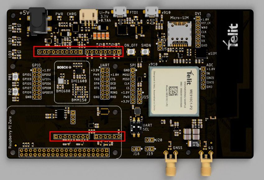
SPECIFICATIONS ARE SUBJECT TO CHANGE WITHOUT NOTICE
NOTICE
While reasonable efforts have been made to assure the accuracy of this document, Telit
assumes no liability resulting from any inaccuracies or omissions in this document, or from
use of the information obtained herein. The information in this document has been carefully
checked and is believed to be reliable. However, no responsibility is assumed for
inaccuracies or omissions. Telit reserves the right to make changes to any products
described herein and reserves the right to revise this document and to make changes from
time to time in content hereof with no obligation to notify any person of revisions or changes.
Telit does not assume any liability arising out of the application or use of any product,
software, or circuit described herein; neither does it convey license under its patent rights
or the rights of others.
It is possible that this publication may contain references to, or information about Telit
products (machines and programs), programming, or services that are not announced in
your country. Such references or information must not be construed to mean that Telit
intends to announce such Telit products, programming, or services in your country.
COPYRIGHTS
This instruction manual and the Telit products described in this instruction manual may be,
include or describe copyrighted Telit material, such as computer programs stored in
semiconductor memories or other media. Laws in the Italy and other countries preserve for
Telit and its licensors certain exclusive rights for copyrighted material, including the
exclusive right to copy, reproduce in any form, distribute and make derivative works of the
copyrighted material. Accordingly, any copyrighted material of Telit and its licensors
contained herein or in the Telit products described in this instruction manual may not be
copied, reproduced, distributed, merged or modified in any manner without the express
written permission of Telit. Furthermore, the purchase of Telit products shall not be deemed
to grant either directly or by implication, estoppel, or otherwise, any license under the
copyrights, patents or patent applications of Telit, as arises by operation of law in the sale
of a product.
COMPUTER SOFTWARE COPYRIGHTS
The Telit and 3rd Party supplied Software (SW) products described in this instruction
manual may include copyrighted Telit and other 3rd Party supplied computer programs
stored in semiconductor memories or other media. Laws in the Italy and other countries
preserve for Telit and other 3rd Party supplied SW certain exclusive rights for copyrighted
computer programs, including the exclusive right to copy or reproduce in any form the
copyrighted computer program. Accordingly, any copyrighted Telit or other 3rd Party
supplied SW computer programs contained in the Telit products described in this instruction
manual may not be copied (reverse engineered) or reproduced in any manner without the
express written permission of Telit or the 3rd Party SW supplier. Furthermore, the purchase
of Telit products shall not be deemed to grant either directly or by implication, estoppel, or
otherwise, any license under the copyrights, patents or patent applications of Telit or other
3rd Party supplied SW, except for the normal non-exclusive, royalty free license to use that
arises by operation of law in the sale of a product.

1VV0301650 Rev. 2                          Page 2 of 32                              2021-03-17

USAGE AND DISCLOSURE RESTRICTIONS
  I.    License Agreements

The software described in this document is the property of Telit and its licensors. It is
furnished by express license agreement only and may be used only in accordance with the
terms of such an agreement.
  II.   Copyrighted Materials

Software and documentation are copyrighted materials. Making unauthorized copies is
prohibited by law. No part of the software or documentation may be reproduced,
transmitted, transcribed, stored in a retrieval system, or translated into any language or
computer language, in any form or by any means, without prior written permission of Telit
 III.   High Risk Materials

Components, units, or third-party products used in the product described herein are NOT
fault-tolerant and are NOT designed, manufactured, or intended for use as on-line control
equipment in the following hazardous environments requiring fail-safe controls: the
operation of Nuclear Facilities, Aircraft Navigation or Aircraft Communication Systems, Air
Traffic Control, Life Support, or Weapons Systems (High Risk Activities"). Telit and its
supplier(s) specifically disclaim any expressed or implied warranty of fitness for such High
Risk Activities.
IV.     Trademarks

TELIT and the Stylized T Logo are registered in Trademark Office. All other product or
service names are the property of their respective owners.
 V.     Third Party Rights

The software may include Third Party Right software. In this case you agree to comply with
all terms and conditions imposed on you in respect of such separate software. In addition
to Third Party Terms, the disclaimer of warranty and limitation of liability provisions in this
License shall apply to the Third Party Right software.
TELIT HEREBY DISCLAIMS ANY AND ALL WARRANTIES EXPRESS OR IMPLIED
FROM ANY THIRD PARTIES REGARDING ANY SEPARATE FILES, ANY THIRD PARTY
MATERIALS INCLUDED IN THE SOFTWARE, ANY THIRD PARTY MATERIALS FROM
WHICH THE SOFTWARE IS DERIVED (COLLECTIVELY “OTHER CODE”), AND THE
USE OF ANY OR ALL THE OTHER CODE IN CONNECTION WITH THE SOFTWARE,
INCLUDING (WITHOUT LIMITATION) ANY WARRANTIES OF SATISFACTORY
QUALITY OR FITNESS FOR A PARTICULAR PURPOSE.
NO THIRD PARTY LICENSORS OF OTHER CODE SHALL HAVE ANY LIABILITY FOR
ANY DIRECT, INDIRECT, INCIDENTAL, SPECIAL, EXEMPLARY, OR CONSEQUENTIAL
DAMAGES (INCLUDING WITHOUT LIMITATION LOST PROFITS), HOWEVER CAUSED
AND WHETHER MADE UNDER CONTRACT, TORT OR OTHER LEGAL THEORY,
ARISING IN ANY WAY OUT OF THE USE OR DISTRIBUTION OF THE OTHER CODE
OR THE EXERCISE OF ANY RIGHTS GRANTED UNDER EITHER OR BOTH THIS
LICENSE AND THE LEGAL TERMS APPLICABLE TO ANY SEPARATE FILES, EVEN IF
ADVISED OF THE POSSIBILITY OF SUCH DAMAGES.

1VV0301650 Rev. 2                          Page 3 of 32                              2021-03-17
APPLICABILITY TABLE
PRODUCTS

      BRAVO EVALUATION KIT

1VV0301650 Rev. 2            Page 4 of 32   2021-03-17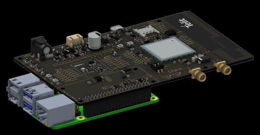
CONTENTS

NOTICE          2

COPYRIGHTS ................................................................................................ 2

COMPUTER SOFTWARE COPYRIGHTS ...................................................... 2

USAGE AND DISCLOSURE RESTRICTIONS ............................................... 3
I.              License Agreements ..................................................................... 3
II.             Copyrighted Materials ................................................................... 3
III.            High Risk Materials ....................................................................... 3
IV.             Trademarks .................................................................................. 3
V.              Third Party Rights ......................................................................... 3

APPLICABILITY TABLE ................................................................................ 4

CONTENTS .................................................................................................... 5

1.              INTRODUCTION .......................................................................... 6

2.              UNPACKING AND PREPARING THE BRAVO BOARD .............. 9
                Bravo Board Content .................................................................... 9
                Strip Connectors Installation ......................................................... 9
                PC USB Drivers Installation ........................................................ 15
                SIM Card .................................................................................... 15
                Power Supply ............................................................................. 16
                GNSS Antenna ........................................................................... 16

3.              CONNECTING THE BOARD TO A PC ...................................... 17
                USB connection between Bravo and PC ..................................... 17
                Switching On the Telit Module .................................................... 18
                Communication Ports.................................................................. 19
                Telit AT Controller Installation ..................................................... 21

4.              USE CASES ............................................................................... 25
                Module Registration, Data Connection to a Test Server.............. 25
                Switch on LED at Startup ............................................................ 29
                Switching Off the Telit Module .................................................... 29

5.              GLOSSARY AND ACRONYMS ................................................. 30

6.              DOCUMENT HISTORY .............................................................. 31

1VV0301650 Rev. 2                                         Page 5 of 32                                             2021-03-17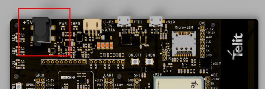
1.          INTRODUCTION
1.1.        Scope
Scope of this document is to give a quick getting start guide for Bravo Evaluation Kit.

1.2.        Audience
This document is intended for Telit Bravo Kit users.

1.3.        Contact Information, Support
For general contact, technical support services, technical questions and report
documentation errors contact Telit Technical Support at:

     •   TS-EMEA@telit.com
     •   TS-AMERICAS@telit.com
     •   TS-APAC@telit.com

Alternatively, use:
http://www.telit.com/support

For detailed information about where you can buy the Telit modules or for recommendations
on accessories and components visit:
http://www.telit.com

Our aim is to make this guide as helpful as possible. Keep us informed of your comments
and suggestions for improvements.
Telit appreciates feedback from the users of our information.

1VV0301650 Rev. 2                         Page 6 of 32                             2021-03-17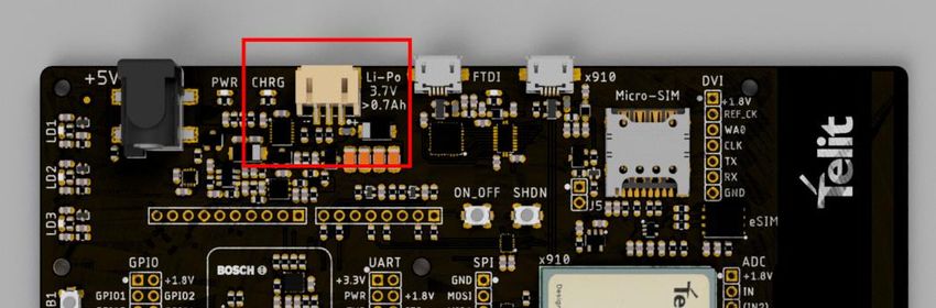
1.4.        Text Conventions

                    Danger – This information MUST be followed or catastrophic equipment
                    failure or bodily injury may occur.

                    Caution or Warning – Alerts the user to important points about integrating the
                    module, if these points are not followed, the module and end user equipment
                    may fail or malfunction.

                    Tip or Information – Provides advice and suggestions that may be useful
                    when integrating the module.

All dates are in ISO 8601 format, i.e. YYYY-MM-DD.

1VV0301650 Rev. 2                              Page 7 of 32                             2021-03-17
1.5.       Related Documents

   •   Bravo EVK HW User Guide, 1VV0301646
   •   ME910C1 HW User Guide, 1VV0301351
   •   xE910 Global Form Factor Application Note, 80000NT10060A
   •   ME910 C1 Quick Start Guide, 80529NT11661A
   •   xE910 Global Form Factor Application Note, 80000NT10060A

1VV0301650 Rev. 2                    Page 8 of 32                 2021-03-17
2.         UNPACKING AND PREPARING THE BRAVO BOARD
           Bravo Board Content
This Quick Start guide will walk you through the steps required to setup and run the Bravo
EVK Board.
Your Bravo kit contains the following:
     -     1 Bravo EVK Board featuring Telit ME910C1-WW IoT OneEdge-enabled
           module
     -     1 Micro-USB cable
     -     Berg connector kit

           Strip Connectors Installation
If the board is to be used with Arduino or Raspberry Pi platforms, strip (“Berg”) connectors
(supplied) must be manually installed.

                     Please use a low-power, temperature-controlled soldering iron with a
                     fine tip and high-quality soldering alloy.

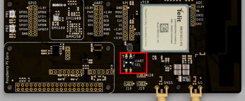
                    Arduino/Raspberry Pi can be connected with Bravo EVK Board Telit
                    ME910C1 UART port. Please identify the UART SEL dip switches as
                    they will be modified depending on the setup:

1VV0301650 Rev. 2                         Page 9 of 32                            2021-03-17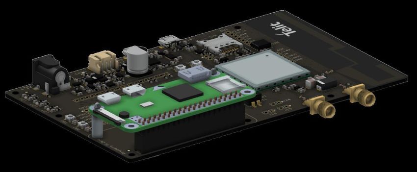
For Arduino Uno compatible connections, please solder Bergs in the highlighted headers
referring to the picture below.

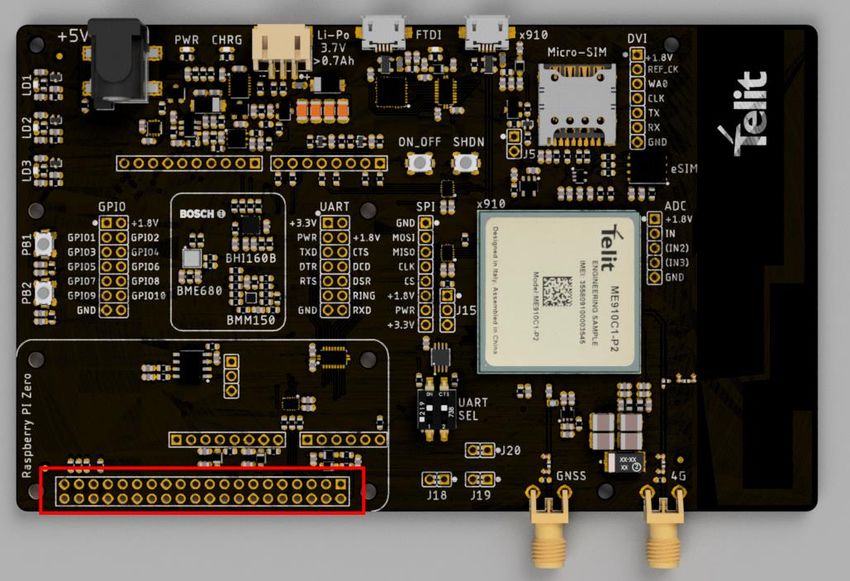
For Raspberry Pi boards, please solder Bergs referring to the highlighted header in the
picture below.

   1) For Arduino, male Berg connectors must be mounted on the bottom side of the
      board, as shown below:

1VV0301650 Rev. 2                        Page 10 of 32                           2021-03-17
The picture below shows the relative mount of an Arduino Uno with the Bravo board 1VV0301650 Rev. 2 Page 11 of 32 2021-03-17
To make Arduino communicate with Bravo EVK Board module’s
                          UART, set UART SEL dip switches as shown below:

                                                        SW1            SW2

                                                        ON             OFF

                    An Arduino Zero or equivalent board (with ARM Cortex M0+
                    processor) is needed to communicate with the Bravo Board, as a
                    dedicated UART interface must be available. Arduino Uno is not
                    suggested because it has a single UART interface and it is shared
                    with the debug port. So developing and debugging will not be
                    possible.

   2) For Raspberry Pi, female Berg connectors must be installed as shown below.:

       The final assembly is showed in the picture below:

1VV0301650 Rev. 2                       Page 12 of 32                           2021-03-17
3) For Raspberry Pi Zero, it is required to mount the female Berg connector on the
top side.
This requires that the male Berg connector on the Raspberry Pi Zero must be
soldered on its bottom: refer to the picture below
1VV0301650 Rev. 2 Page 13 of 32 2021-03-17It is suggested to mount two 11mm teflon spacers between Bravo and the
open hardware boards, such as (in example) Wurth PN 709 670 110
To make Raspberry Pi boards communicate with Bravo EVK Board
module’s UART, set UART SEL dip switches as shown below:
SW1 SW2
OFF ON
1VV0301650 Rev. 2 Page 14 of 32 2021-03-17Bravo EVK Board exports also all ME910C1-WW UART signals (full
HW flow control available) on “UART” header. To use this connector,
set UART SEL dip switches as shown below:
SW1 SW2
ON ON
Important: The connector leverages a dedicated level shifting FTDI. To
communicate with the ME910C1-WW UART, the external host’s UART
VCC must be connected to PWR pin (which will then provide the
reference for that side of the translation).
PC USB Drivers Installation
Drivers are required to allow communication between your PC and the Telit module.
Communication can take place either through the native USB port or the USB to serial
converter (USB connector marked “FTDI”).
- The driver package for the FTDI serial to USB adapter can be downloaded
from: https://www.telit.com/bravo/ selecting “USB to Serial Drivers”
- The Driver package for the ME910 USB port can be downloaded from
https://www.telit.com/bravo/ selecting “Windows 10 Drivers”
Please follow the instructions provided by the PDF file contained in the .zip archive.
SIM Card
In order to allow the module to register and exchange data on a mobile network, insert a
data-capable SIM card in the SIM holder on the Bravo board. The format supported is
Micro-SIM.
Please make sure the subscription supports data traffic on LPWA (either Cat-M or NBIoT)
or GSM/GPRS radio access technologies.
1VV0301650 Rev. 2 Page 15 of 32 2021-03-17Before using the SIM card with Bravo, it is suggested to disable SIM PIN
request on the SIM card itself. If PIN is enabled on the SIM card, please use
the AT+CPIN command to check status or unblock SIM.
Power Supply
The board itself contains a 3.7V linear power supply and can be powered:
- Through the native USB port, using the supplied USB cable
- By connecting an external 5V DC power supply to the coaxial connector marked
“+5V”.
Powering the board through the USB port relies on the host device
(eg PC or USB hub) capability to provide at least 500 mA.
It is highly recommended to use either an external DC power
supply or a battery pack.
Please check carefully that the external power supply:
- Provides 5V DC (while not exceeding 7V at most)
- Can provide at least 600 mA continuously
- By connecting a 3.7 V battery pack to the connector marked “Li-Po 3.7V”.
Please read carefully the battery pack and charging requirements
described in the Bravo EVK HW Manual.
GNSS Antenna
The Telit ME910C1-WW module embeds a high-performance GNSS receiver: its usage
requires connecting a GNSS antenna (not supplied) to the SMA connector labeled
“GNSS”.
1VV0301650 Rev. 2 Page 16 of 32 2021-03-173. CONNECTING THE BOARD TO A PC
Connecting Bravo to a PC is suggested to test board communication and familiarize with
module AT commands.
USB connection between Bravo and PC
• Connect the micro-USB cable between the x910 port on the Bravo Board and the
USB port of your PC or laptop.
Alternative: The board also provides access to the ME910
UART using an FTDI USB-to-serial converter. To enable it,
identify the UART SEL dip switches:
SW1 SW2
OFF OFF
Please refer also to picture below:
1VV0301650 Rev. 2 Page 17 of 32 2021-03-17• Optional: supply the board with the preferred solution:
DC power supply barrel connector:
or Battery connector:
Switching On the Telit Module
After connecting the USB cable to the USB x910 port and optionally the power adapter to
the power Jack or the battery to the Li-Po connector, the board is powered but the ME910
is still turned off.
After connecting the USB cable to the USB x910 port, new USB devices connected to the
computer will not be visible.
• To turn on the MCU keep the ON/OFF button pressed for at least 5 seconds. No
led is switched on when the MCU is turned on.
When the MCU is powered on, three new USB devices will be visible within Windows
Device Manager.
By default, both Windows and Linux detect the USB devices as a modem and lock the
devices for communication tasks. To avoid this:
• In Windows, open “Device Manager” and expand Network Adapters group, then
disable Telit USB WWAN Adapter. This must be done for every board.
1VV0301650 Rev. 2 Page 18 of 32 2021-03-17An alternate procedure is to go to Control Panel ► Network and Sharing Center
► change Adapter settings ► right-click on Cellular connection and disable it.
• On Linux, configure ModemManager to exclude the devices from use as modems
inserting the ID in ModemManager configuration files
Communication Ports
Two of the three USB devices can be used as terminals for sending AT commands to the
MCU.
If connecting the USB cable to the FTDI USB port the board will be powered, but the Telit
module will not turn on automatically.
On the computer, a new FTDI USB device will be mapped because the FTDI interface
chip is powered by the USB port itself.
The FTDI USB connection will be able to receive AT commands once the MCU is
switched on. To turn on the Telit module, follow the instructions above.
To use x910 USB COM ports:
• Go to Control Panel > Device Manager and check one of the USB Modems
COM Port number.
• Right click on one of the two Telit USB Modem entries, select Properties, then
Modem Tab.
1VV0301650 Rev. 2 Page 19 of 32 2021-03-17To use FTDI ports, check “Ports (COM & LPT)” group: there will be a USB Serial Port (COM X) entry. This port will allow to communicate over the Main UART COM Port of ME910 MCU. 1VV0301650 Rev. 2 Page 20 of 32 2021-03-17
Telit AT Controller Installation
Telit AT controller is a terminal application designed to send AT commands to Telit IoT
modules. It can be downloaded for free at the following address:
https://www.telit.com/bravo/ selecting “Telit AT Controller”
Unzip the folder and run Setup_TATC_x.x.xx_XFP_x.x.x.msi file.
Upon successful installation, the following files will be created on your desktop:
   -   Telit At Controller.lnk
   -   Xfp.lnk

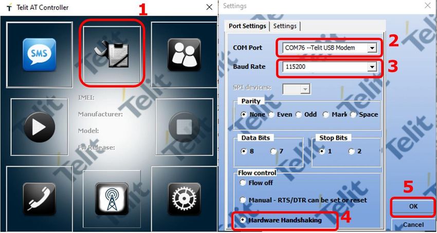
Double click on Telit AT controller icon to open the application.
Click the Settings Icon

Then Port Settings to setup the AT port parameters such as:
   -   COM port
   -   Baud rate
   -   Parity
   -   Data Bits
   -   Start Bits
   -   Flow Control, and click OK.

1VV0301650 Rev. 2                         Page 21 of 32                              2021-03-17
Upon configuration, click Connect button:

Module information such as IMEI, Manufacturer name, Model number and FW release
version will be displayed:

1VV0301650 Rev. 2                       Page 22 of 32                     2021-03-17
Click on AT Terminal to start the AT Terminal window:

Issue the following AT commands to verify firmware version and options
   •   AT#SWPKGV
   •   AT#SWOPTIONS

1VV0301650 Rev. 2                      Page 23 of 32                     2021-03-17
1VV0301650 Rev. 2 Page 24 of 32 2021-03-17
4.           USE CASES
The following use cases are for example only and show command sequences. Each
command is documented in the Telit ME910 AT Commands manual: users are
encouraged to consult it for further details.
             Module Registration, Data Connection to a Test Server
The following example shows a simple AT command sequence to perform the following
actions:
     •   Check Module SIM and registration status
     •   Configure Module APN
     •   Activate PDP Context to start a data connection
     •   Connect to a test server and open a data socket
     •   Send data to a test server
     •   Close connection

Send the commands
     •   AT+CPIN?
     •   AT+CREG?
     •   AT+CGREG?

 AT+CPIN?                    Check PIN status
 +CPIN: READY
 OK

 AT+CREG?                    Check Circuit Switched Registration status
 +CREG: 0,1
 OK

 AT+CGREG?                   Check Packet Switched Registration status
 +CGREG: 0,1
 OK

Configure the APN for the SIM card in use:
     •   AT+CGDCONT=1,IP,””
Please replace “” with the APN to be used with your SIM card.

                    Please consult your Network provider to check the correct APN.
                    Some networks have different APNs depending on the contract, profile etc

1VV0301650 Rev. 2                         Page 25 of 32                              2021-03-17
Activate the PDP context with:
AT#SGACT=1,1
And connect to the server using the socket dial command (in ONLINE MODE)
AT#SD=1,0,10510,”modules.telit.com”
1VV0301650 Rev. 2 Page 26 of 32 2021-03-17Type “hello” (without quotes) in the input field an press Enter. The server will reply with an echo message: To exit ONLINE mode, type +++ and press Enter: Check socket status and exchanged data with AT#SS=1 AT#SI=1 1VV0301650 Rev. 2 Page 27 of 32 2021-03-17
Close the socket and disable the PDP context with the following commands:
AT#SH=1
AT#SGACT=1,0

1VV0301650 Rev. 2                      Page 28 of 32                        2021-03-17
Switch on LED at Startup
It is advisable to automatically turn on at least one LED at MCU wakeup: this is useful as
visible feedback to know whether the IOT Module is powered ON or OFF.
The BRAVO Board is equipped with 3 LEDs (connected to GPIO 1, 9 and 10) that can be
enabled/disabled using the following AT commands:
To turn ON the leds:
   •   AT#GPIO=1,1,1
   •   AT#GPIO=9,1,1
   •   AT#GPIO=10,1,1
To turn OFF the leds:
   •   AT#GPIO=1,0,1
   •   AT#GPIO=9,0,1
   •   AT#GPIO=10,0,1
To turn the leds on permanently, so that they automatically turn on at module wakeup,
please send the following command(s):
   •   AT#GPIO=1,1,1,1
   •   AT#GPIO=9,1,1,1
   •   AT#GPIO=10,1,1,1

           Switching Off the Telit Module
To turn off the MCU you can either press the shutdown button or press the ON/OFF
button for at least 5 seconds.

1VV0301650 Rev. 2                        Page 29 of 32                            2021-03-17
5. GLOSSARY AND ACRONYMS
Description
TTSC Telit Technical Support Centre
USB Universal Serial Bus
HS High Speed
DTE Data Terminal Equipment
UMTS Universal Mobile Telecommunication System
WCDMA Wideband Code Division Multiple Access
HSDPA High Speed Downlink Packet Access
HSUPA High Speed Uplink Packet Access
UART Universal Asynchronous Receiver Transmitter
HSIC High Speed Inter Chip
SIM Subscriber Identification Module
SPI Serial Peripheral Interface
ADC Analog – Digital Converter
DAC Digital – Analog Converter
I/O Input Output
GPIO General Purpose Input Output
CMOS Complementary Metal – Oxide Semiconductor
MOSI Master Output – Slave Input
MISO Master Input – Slave Output
CLK Clock
MRDY Master Ready
SRDY Slave Ready
CS Chip Select
RTC Real Time Clock
PCB Printed Circuit Board
ESR Equivalent Series Resistance
VSWR Voltage Standing Wave Radio
VNA Vector Network Analyzer
1VV0301650 Rev. 2 Page 30 of 32 2021-03-176. DOCUMENT HISTORY
Revision Date Changes
0 2020-03-18 Initial Revision
1 2020-10-02 Added Arduino and Raspberry Pi mount and
usage details
2 2021-03-17 Correction in dip-switch description for
Raspberry Pi and Arduino
1VV0301650 Rev. 2 Page 31 of 32 2021-03-17[01.2017]
Mod. 0809 2017-01 Rev.8You can also read


