WALLS LAYOUT Approved Methods - Habitat for Humanity Cabarrus County
←
→
Page content transcription
If your browser does not render page correctly, please read the page content below
WALLS LAYOUT
                                   Approved Methods
                                               March 8,2021

This manual is a derivative of the copyrighted work of Anna Gallant Carter titled Habitat for Humanity
Charlotte Construction Manual; Approved Home Building Methods. Anna has given Cabarrus Habitat for
Humanity her permission to make this derivative available online on a website accessible to the public
and in print for the benefit of Habitat for Humanity Cabarrus County’s staff and volunteers as well as
other Habitat for Humanity affiliates. This agreement does not transfer to Habitat for Humanity
Cabarrus County, its affiliates, staff or volunteers, the author’s exclusive right to sell, rent, lease, or
lend copies of the work to the public.

             Walls Layout                    Mar 8,2021                     Page 1 of 30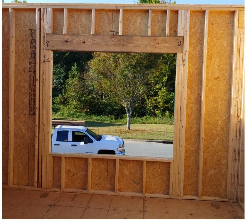
Note to the Reader: Due to differing conditions, tools, and individual skills, the authors of this manual
and Habitat for Humanity of Charlotte assume no responsibility for any damages, losses incurred,
deaths, or injuries suffered as a result of following the information published in this manual. Although
this manual was created with safety as the foremost concern, every construction site and construction
project is different. Accordingly, not all risks and hazards associated with homebuilding could be
anticipated by the authors of this manual and Habitat for Humanity of Cabarrus. Always read and
observe all safety precautions provided by any tool or equipment manufacturer, and always follow all
accepted safety procedures. Because codes and regulations are subject to change, you should always
check with authorities to ensure that your project complies with all local codes and regulations.

             Walls Layout                     Mar 8,2021                     Page 2 of 30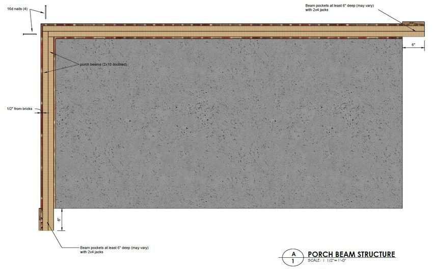
Table of Contents
Layout Safety Guidelines ........................................................................................................................................................ 4
Steps in the layout ................................................................................................................................................................... 5
Task List – Crown Studs ......................................................................................................................................................... 5
   Quality Checkpoints ......................................................................................................................................................... 5
Task List - Walls Layout......................................................................................................................................................... 5
   Quality Checkpoints ......................................................................................................................................................... 5
Task List - Cutting Wall Plates ............................................................................................................................................... 6
   Quality Checkpoints ......................................................................................................................................................... 6
Task List - Marking Wall Plates ............................................................................................................................................. 7
   Quality Checkpoints ......................................................................................................................................................... 7
Layout Tool, Equipment & Material List ........................................................................................................................... 8
   Tools Each Wall Layout Crew Member Will Need ....................................................................................................... 8
   Tools Wall Layout Crew Will Need on site..................................................................................................................... 8
   Tools and Equipment Needed On Site ............................................................................................................................ 8
   Walls Layout Material List .............................................................................................................................................. 8
Standard Marking Symbols ................................................................................................................................................. 9
   Component Sizes for the layout ........................................................................................................................................ 10
General Instructions For Wall Layout............................................................................................................................. 12
   Laying Out and marking the House Plan on the Floor ............................................................................................... 12
       Compare Overall Floor Dimensions to the House Plan ................................................................................................ 12
       Exterior Walls - Mark ................................................................................................................................................... 12
       Interior Walls -Mark ..................................................................................................................................................... 13
Prepare Bottom and Top Wall Plates............................................................................................................................... 14
       Inventory Wall Plates ................................................................................................................................................. 14
   Measure and Cut Exterior Wall Plates ......................................................................................................................... 14
       Nail Together and Square Cut the End of Wall Plates ............................................................................................ 14
       Mark Exterior Side Wall Plates for 16" Centers ..................................................................................................... 16
   Measure and Cut Interior Wall Plates .......................................................................................................................... 24
   Special Studs .................................................................................................................................................................... 26
   Crown Studs .................................................................................................................................................................... 29
   Framing Jig...................................................................................................................................................................... 30

                                 Walls Layout                                         Mar 8,2021                                       Page 3 of 30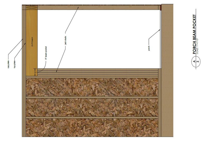
Layout Safety Guidelines
Review these guidelines with each crew member at the start of the day or as they arrive on site.
             “NO JOB IS SO IMPORTANT THAT IT CAN’T BE DONE SAFELY”

Speak up if something looks unsafe. An observer can spot danger quicker than a worker.
Know where water & a first aid kit are located. Tell the site supervisor immediately in the event of an
injury.
Habitat requires that ear protection be used when using power saws.

Habitat requires safety glasses not just when using power saws, but at all times.
Utility knives - keep your hand out of the blade’s path. Retract blade when not in immediate use. A
sharp blade is safer than a dull one. Safely dispose of used blades.
Power Saws:

   •   Only crew members with power saw experience can use them. A busy work day is not the time
       to teach saw skills nor is it the time to learn saw skills.
   •   Habitat requires that ear and eye protection be used when using power saws.
   •   Never start a saw with the wood contacting the blade. This can be very dangerous.
   •   Never cut small pieces with a power saw. The saw can easily pull the piece in bringing your
       hand with it.
   •   Don’t bind the blade of any saw – listen for it. Back off and re-support lumber.
   •   Keep electric cords out of the way of the saw and out from underfoot.
   •   Don’t cross hands over to stabilize material on the miter saw. Find another way or get help.
       Guards on saws must be in place & operating. If it is necessary to manually retract the guard be
       very careful that your hand is out of way of the blade,

Remove nails before discarding lumber. Discarded material must be placed in the designated area.

No loose clothing or hair that can get caught in power tools.
Wear appropriate clothing for the task including work boots that protect from falling objects, have a
nonskid sole & resist nail penetrations. No open toed shoes allowed.
Tools must be in a safe condition (meet OSHA standards, i.e. no nicks in cords.).

Think & concentrate on your task.
If you are uncertain about how to do a task, or how to operate a power tool, ask your crew leader.

             Walls Layout                    Mar 8,2021                     Page 4 of 30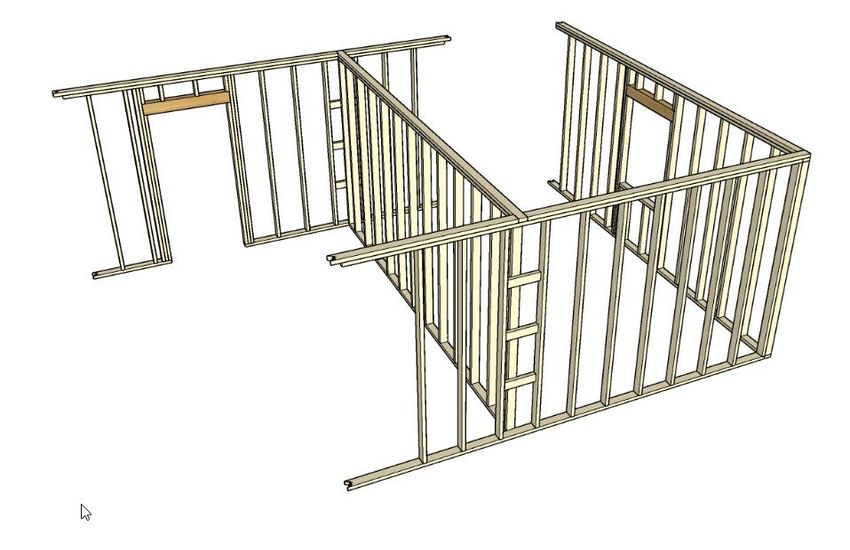
Steps in the layout
   1.   Crown the studs for the walls
   2.   Mark the exterior and interior wall plate locations on the floor.
   3.   Cut the exterior and interior wall plates
   4.   Lay the top and bottom plates (exterior first) in proper position on the floor and mark the
        locations of studs, windows openings and door openings

Task List – Crown Studs
Quality Checkpoints

        Examine each of the wall studs and clearly mark the crown side.
        Stack all crowned studs in an area that be easy to reach for building of the walls.

Task List - Walls Layout

Staffing

Staff Site Supervisor
Layout Task Leader
2 Additional Volunteers

Tasks to Be Completed and Crew Sizes

 Mark the exterior walls                               2-3 people
 Mark the interior walls                               2-3 people

Quality Checkpoints

        All walls are marked clearly with red chalk on the floor.
        Errors fully erased
        Walls are parallel
        Critical dimensions are reviewed (bathtub, hallway, doors)
        2x6 plumbing walls are marked correctly.
        All wall intersections are clearly marked
        Interior walls located over joists or wood bridging
        Account for toilet, tub, & HVAC return locations
        All lines on floor are sprayed with clear lacquer to preserve the marks

             Walls Layout                     Mar 8,2021                    Page 5 of 30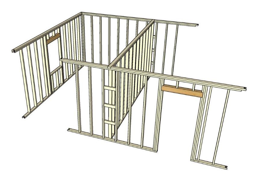
Task List - Cutting Wall Plates

Staffing

Staff Site Supervisor
Layout Task Leader
2-3 Additional Volunteers

Tasks to Be Completed and Crew Sizes

 Inventory the plate order                               1 person
 Nail together and trim plates                           2-3 people
 Lay out the plates                                      3-4 people

Quality Checkpoints

        Plates are cut accurately, within1/16"
        All walls have plates in place

              Walls Layout                       Mar 8,2021           Page 6 of 30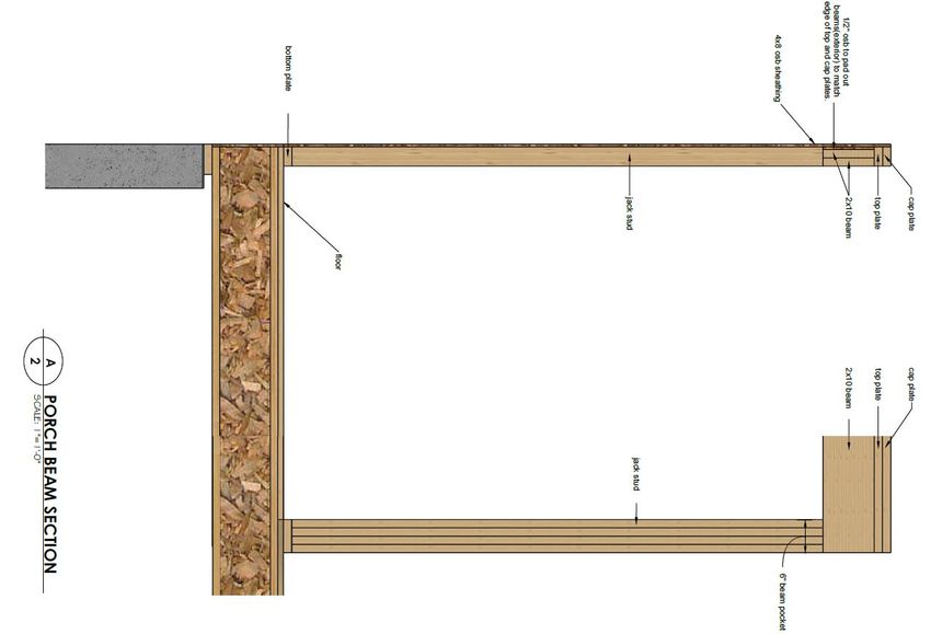
Task List - Marking Wall Plates
Staffing

Staff Site Supervisor
1   Additional Volunteer

Tasks to Be Completed and Crew Sizes
   ____ Mark corners                                                       1 person
   ____ Mark wall intersections                                            1 person
   ____ Locate windows, exterior doors and exterior ladders                1-2 people
   ____ Mark exterior studs                                                1-2 people
   ____ Mark interior doors                                                1-2 people
   ____ Mark special studs                                                 1 person
   ____ Mark interior ladder tees and studs                                1-2 people
   ____ Review layout                                                      1-2 people

Quality Checkpoints

       All components are proper size and marked clearly
       All intersections have appropriate components
       Exterior wall studs spaced no greater than 16" o.c.
       Interior wall studs spaced no greater than 16" o.c.
       Interior doors have a king and jack studs on both side.
       Exterior doors have a set of 2 king and a jack stud on both sides.
       Exterior windows have a king and jack stud on both sides.
       Exterior windows that are wide have a set of 2 king and 2 jack studs on both sides.
       Exterior walls that have porch beam pockets are properly marked on the top and bottom plates.
       Bathtubs have stud turned sideways centered at a point where it will provide a surface to attach
       side flange of tub.
       All errors on plates are completely erased

             Walls Layout                   Mar 8,2021                     Page 7 of 30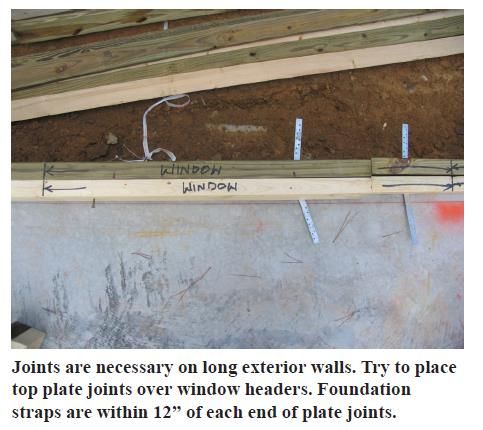
Layout Tool, Equipment & Material List

Tools Each Wall Layout Crew Member Will Need
Hammer (16 oz. Min.)
Nail Apron
Retractable Utility Knife with extra blades
Retractable Measuring Tape (16' Minimum)
Square (Speed or Combination)
2 Pencils
Safety Glasses
Ear Protection
Red & Black Crayon or permanent marker
Water

Tools Wall Layout Crew Will Need on site
Metal Measuring Tape (50-100’)
Chalk Line (Red Chalk)
Chalk Line (Blue Chalk for corrections)
12 Gauge Drop Cord (50')

Tools and Equipment Needed On Site
12 Gauge Drop Cords (100')
Three or Four-Way Electrical Box
Circular Saw
Saw Table (optional)
Saw Horses (optional)
Components (know their sizes)
     • Ladders
     • Tees 2x4, 2x6
     • Windows (two sizes)
     • Corners
Flat bar and cat’s Paw (nail puller)
Broom

Marking Devices
Red Lumber Marking Crayon
Permanent Markers
Clear Lacquer Spray Enamel. Used to protect chalk lines.
Spray jig
Floor Plan

Walls Layout Material List
2x4s Bottom Plates – various sizes (12’,16’,10’,8’)
2x4s Top Plates– various sizes (12’,16’,10’,8’)
2x4s Cap Plates– various sizes (12’,16’,10’,8’)
2x4s Studs for 92 5/8” for 8’ walls; 104 5/8” for 9’ walls
2x6 Plates for plumbing walls
16d common nails as well as galvanized 16d common nails when nailing treated lumber.

             Walls Layout                     Mar 8,2021               Page 8 of 30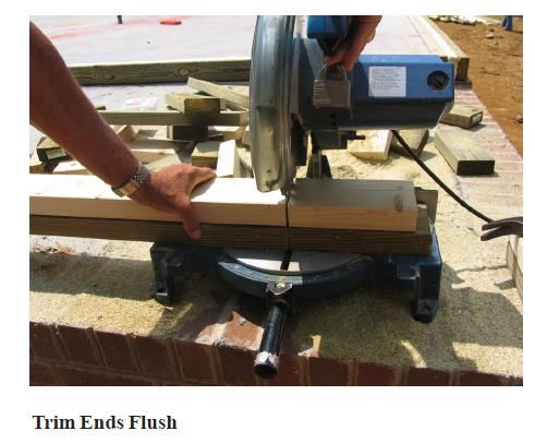
Standard Marking Symbols

Use standard symbols and notations when marking plates for framing components. Arrows drawn to the
layout lines on the plates show where to place prefabricated components.
·Single Studs   |X|
·Double Studs | X | X |
·Corners        |COR| or |XXX or |CAR| |COR|
                (XXX can denote solid exterior corners, whereas
                CORN can be used for corner components for interior corners that are not solid.)
·Beam Corner    |BEAM CORN|
·Beam Post      |BEAM POST|
·Wall           | WALL |
·Interior Doors ||
·Ladders        ||
·Exterior Doors |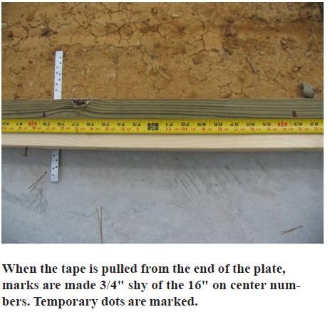
Component Sizes for the layout

Window components come in two sizes (see floor plan). When measuring for the window add 6" to the
window size to determine the component size. The 6” is for the left and right jack and king studs as
shown in the drawing below. (This may vary depending on the window manufacturer.)

For example, a 3’-0" (36") window would have a component size of 42". Mark the outside dimensions
of the window components with black marker and label with the words |WINDOW| or |SHORT
WINDOW|. The components for the window include (on each side) the king and jack studs. Thus the 6”
addition to the window size.
       2’-8" x 4’-4" = 38" outside dimensions
       2’-8" x 3’-0" = 38" outside dimensions
Exterior door. To determine exterior dimensions of the components, take the actual door size (see plan)
and add 11". Current code requires 2 kings and a jack on each side of exterior doors. This adds 9” to the
component and ¾” for the door jamb on each side (with room to allow for plumbing the door in the
opening).
       3’-0" door (36") = 47" outside dimensions

       2’-8" door (32") = 43" outside dimensions
Ladders are 14½" wide and are placed within the 16" o.c. stud layout, allowing the intersecting interior
wall to attach at any point within the ladder. These are used on exterior wall to avoid blocking insulation

             Walls Layout                     Mar 8,2021                    Page 10 of 30
in the wall. These are used to support butting interior walls. See the ladder location strategy in the
drawing below.
Tees are 6½" wide for 2x4 walls and 8½" for 2x6 walls. These are used on Interior walls to support a
butting interior wall.
Corners are made of either three studs placed side by side (“solid corner”) or two studs with blocking in
between. Due to insulation requirements, corners on the exterior of the house must be Cal COR (2 studs
nailed in an L. All interior corners can be made with blocking between the studs.
Interior Doors are laid out inside of jack to jack stud to provide an opening 2" wider than the nominal
dimension of the door (a 28" door would have a 30" opening). Mark for each jack stud on each side of
the king stud.
Tub Support is set up 32” OC from the back wall on each side of the location of the tub and turned
sideways for support of the tub tabs. See sketch below.
Walls Layout Mar 8,2021 Page 11 of 30General Instructions For Wall Layout
In this section you will be marking the floor with the locations of the interior and exterior walls,
preparing the top and bottom wall plates, and marking them for the locations of studs (including jack
and king studs as well as cripple studs), doors, windows, ladders. You will also prepare the studs,
window and door components (king and jack studs as well as the header) that will be used in the next
phase of building and erecting the walls.
Laying Out and marking the House Plan on the Floor
Note the following important guidelines:
1. Layout can be done in parallel while volunteers are preparing the wall studs, door and window com-
ponents (these are all specified in the house plans).
2. Verify tub and shower sizes prior to layout. Wall measurements may need to be modified. For exam-
ple the width of a bathroom may be dictated by the tub size or a wall depth may depend on how deep
a shower is.
3. Make sure the different sheets of plans you have are consistent. Draw through any drafts that may
have reverse or modified information then what is to be built.
4. Confirm rough window openings before commencing. All second story windows must be tall
enough to allow for code requirement for egress.
Compare Overall Floor Dimensions to the House Plan
Measure and compare overall dimensions of the floor and the house plan before laying out the walls. If
the existing floor dimensions do not match the plan, adjust the plan. Add or remove width and length
from bedrooms, living rooms, or dining rooms. Do not adjust dimensions of bathrooms, utility rooms, or
hallways which have plumbing fixture and/or code requirements. If the floor is more than 1" out of
square, causing walls to not be parallel, let the Site Supervisor know before adjustments are made.
Reminder: Check for square across diagonals, check for parallel by sampling the distance between two
walls in several places.
Exterior Walls - Mark
On wood floors, mark at each end of the wall 3½" (check with site supervisor) in from the outside edge
of the rim board at each end of each exterior wall. For long walls, place an additional mark midway
along the wall. Using those marks, chalk a red line (red is water-resistant) around the entire perimeter of
the house.
Mark on the floor with a permanent marker along the chalked line for exterior doorways and interior
wall intersections. Check exterior doorway locations to be sure that they match porch layouts and that
they center on stairs and brick sills.
Be sure to spray wall lines on the floor with the lacquer seal.
Walls Layout Mar 8,2021 Page 12 of 30Interior Walls -Mark
Layout the location of interior walls, marking in pencil on both sides of where the 3½" and 5½" walls
are to be located. Layout long walls (hallway walls) first. Next, layout the walls that extend from the
side of the house to the hall (or other long) walls. Complete the layout of a portion of the house. When
certain of the layout, snap chalk lines to establish the location of the interior wall plates.
Remember that all hallways must have a minimum rough opening dimension of 37½" (36" after drywall
finishing) to pass code. If necessary, take space out of bedrooms to ensure that hallways are wide
enough. Make sure bathroom and utility closets dimensions are not less than required by the plans after
making adjustments.
Be sure to spray wall lines on the floor with the lacquer seal.
Important Things to Remember when marking for exterior and interior walls
A. Habitat plans show outside walls at 3.5" in from the outside because they include sheathing which
will cover the walls and the rim board.
B. Layout dimensions for all interior walls are 3½" except plumbing walls, which are 5½" wide. On
some floor plans, a section of the wall behind the tub will be 5½", stepping back to 3½" to make
room for the bathroom door casing and countertop.
C. Keep walls parallel. If adjustments are necessary, let the Site Supervisor know.
D. Use red or black crayon to circle all pencil layout marks. This makes them easier to find when
snapping chalk lines.
E. Use red chalk to snap lines and be sure the lines are easy to see. If a mistake is made, erase the
line, rubbing it out before remarking.
Walls Layout Mar 8,2021 Page 13 of 30Prepare Bottom and Top Wall Plates
Inventory Wall Plates
Check the house plans to determine the appropriate exterior wall plate lengths and where top plate joints
should occur, which usually is over a window component. Some joints may occur along a length of wall,
and if so, wall framing can be strengthened by placing studs at the end of each wall section to be joined,
this provides back to back studs in each section that can be nailed together when adjoining wall sections
are raised. Inventory the lengths of all plates designated on the house plans and ensure that framing
material of adequate length and quantity is on site to fabricate top and bottom plates per the house plan.
Measure and Cut Exterior Wall Plates
It is helpful to have one or two designated cutters and at least two other people measuring and placing
plates on their designated spot on the floor once they are cut.
Exterior plates should be cut first, beginning with side walls. This will ensure that exterior wall plates
are as long as possible with joints breaking at window components. Remember when determining where
joints are placed, that cap plates must overlap top plate joints by at least 4' and break over a stud or a
header. The exterior side walls run long. Start from the rear and work towards the front, cutting the last
set of plates to the actual dimension (the cut sheet is just a guide).
Upper plates MUST be sized to place any mid-wall joints over a window or door header or over a stud
(per building code). On walls that require multiple upper and bottom plates (or have a joint), you may
stagger the upper and bottom plates by placing the upper and bottom plates at opposite ends of the wall
and join at the top and bottom with separate studs (the joint between upper plates must be centered on a
stud, not located above a door).
Exterior side wall plates extend to the outside edge of the band joists or rim board. In other words, the
long walls run long. Mark 3 ½" inches in from each end of the side wall plate. This line will match up
with the intersecting wall’s chalk line. Determine the length of plates by measuring accurately along the
chalk lines. Lay plates along the exterior walls on their sides with the top plate facing in. Plates should
butt tightly.
Nail Together and Square Cut the End of Wall Plates
Temporarily nail all plates together with 16d nails (do not drive all the way through). It is helpful to
mark the nominal length (8, 10, 12, 14, or 16 feet) on the plate. Nail plates so that one end is flush; then
trim the other end flush if necessary.
Label Top Plate, Bottom Plate on ALL wall sections so that when removed you can easily identify
where each wall should be placed.
The front and back wall plates can be measured and cut as they fit between the inside of the side wall
plates.
Walls Layout Mar 8,2021 Page 14 of 30Walls Layout Mar 8,2021 Page 15 of 30
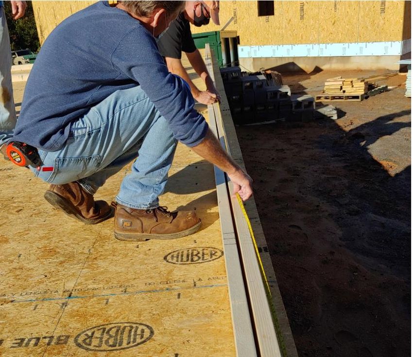
Mark Exterior Side Wall Plates for 16" Centers

Check the placement of the plates along the exterior side walls to be sure that they are turned on their
edges, match layout lines, and are tightly butted. A stud designation is placed on the plate end of the side
walls. Using a steel tape and black marker, place lines on the top edge of the plates on 16" centers,
starting at the back of the house and working toward the front. The first line should be 151/4" from the
end, the next, 311/4", the next, 471/4" and so on. These lines are preliminary and mark the edge of studs
and an X is place after this line to designate the location of a stud and other framing components.
Front and back walls butt into side walls. A stud designation is placed on the plate end of the front and
back walls. When marking front and back walls for studs, hold the tape 31/2" past the end of the plate and
mark the first line at 151/4" from the end. Draw a line on this mark and place on X after this line to designate
the stud locations. Continue this process to the end of the wall.
Next, go to the front of the house, and mark dots at 113/4 ", 273/4", and 433/4" from the end of the plates.
Marking the last four feet in this manner allows the corner sheathing to have its interior edge fall on the
      4

center of a stud. (Corner bracing starts flush with the corner framing member. The OSB edges do not
overlap.) Check this in both directions off each corner.
Mark the exterior walls that will have porch beam pockets and place the 4 jack studs marks on the plate.
Lingo Tip: When pulling a tape from the back of the house, “Laying Ahead” means that when marks are
placed for 16" o.c., they are made 3/4" before the 16" mark (151/4"), with the “X” for the stud “laying
ahead” of the mark.
Be sure to account for the following when you mark the plates:
               a.    Door opening on exterior walls with 2 kings and a jack stud on each side of the door
                    opening. Mark locations of the cripple on top plate.
               b.   Window opening (standard size) with a king and a jack stud on each side of the
                    window opening. Mark locations of the cripple on top plate and on bottom plate.
               c.   Window opening (wider size) with 2 king and 2 jack studs on each side of the window
                    opening. Mark locations of the cripple on top plate and on bottom plate.
               d.   Label the King and Jack stud locations with “K” or “J” to specify the location of the
                    pre-built window and door components during wall assembly. The Jack studs will
                    always be to the inside of the King Studs. Stud width is always 1½”. Label the
                    location of both King and Jack studs on the bottom plate but label only the King stud
                    on the upper plate.
               e.   Some dimensions must be exact or must meet a minimum. Examples are as follows:
                     • Tubs: 601/4" between walls rough opening
                     • Hallways: 37½" rough opening minimum
                     • Doors: Wall sections that contain doors must be at least as long as the nominal
                       door size plus 8" (4" each side). This leaves room for door framing and case
                       moldings. Pay particular attention to short walls that contain doors and doors next
                       to cabinets.
               f. Label Top Plate, Bottom Plate on ALL wall sections so that when removed you can
                  easily identify where each wall should be placed.

              Walls Layout                      Mar 8,2021                      Page 16 of 30
Walls Layout Mar 8,2021 Page 17 of 30
Below are sketches of the typical walls, window, door and porch beam pocket to help with the marking
of the plates.

            Walls Layout                   Mar 8,2021                   Page 18 of 30
Walls Layout Mar 8,2021 Page 19 of 30
Keep in mind that the layout of the exterior walls is designed to support the placement of exterior OSB
sheathing on studs centers. OSB sheathing on short walls (those that are tucked in between long walls) overlaps
the long walls by 3.5”

The sketches below depict the beam strategy where the porch beams are configured as L shaped or as C shaped.
This is important to keep in mind as you lay out the exterior plates where the beams for the porches will be
supported by multiple jack studs.

                    Walls Layout                   Mar 8,2021                    Page 20 of 30
Walls Layout Mar 8,2021 Page 21 of 30
Walls Layout Mar 8,2021 Page 22 of 30
Walls Layout Mar 8,2021 Page 23 of 30
Measure and Cut Interior Wall Plates
Measure for and cut plates for the longest walls (usually hallways) first. Place plates on the layout lines
as they are cut. Continue measuring and cutting, finishing with the shortest walls. Place plates on their
sides along their layout lines.

Check the floor plan to make sure no walls have been left out. Plates should butt tightly.

See drawings below.

             Walls Layout                     Mar 8,2021                     Page 24 of 30
Mark Interior Wall Plates for 16" Centers and Components
Check the placement of the plates for interior walls to be sure that they are turned on edge, match layout
lines, and butt tightly together. Start with long (hall) walls at the back of the house and work toward the
front of the house. Use a metal tape and black marker to temporarily mark the plates for studs 16" on
center. Mark the stud location (using an X for the stud) to the right of the line. The first stud starts at the
end of the plate. Each successive stud is on 16” spacing marked from the starting end of the plate until
the end of the plate is reached.
Walls running perpendicular to the side of the house should be marked similarly, starting at the outside
walls. Short walls should also be marked for stud and component placement using 16" stud placing.
After preliminary 16" centers are marked, ends of plates should be checked and marked for a stud (X) or
a Corner (CORN).
Where walls intersect a plate, layout lines should be transferred from the floor to the plate using a speed
square. The layout lines should be transferred to both sides of the plates and should be marked with a |
WALL | symbol in pencil. After the wall symbol is placed on the plate, two additional lines, spaced 1½"
Walls Layout Mar 8,2021 Page 25 of 30to either side of the| WALL | symbol should be placed on the plate to indicated the outside edges of the Tee component. The plate then is marked with a tee symbol, ||. The side of the plate that receives the intersecting wall is marked with a | WALL | symbol. Mark Interior Doors Next, review the plan to determine door locations, sizes, and which side will be the hinge side. Framing for interior doors is two inches more than the size door specified on the plan. Cased openings, where no door is to be installed will be dimensioned on the plan, giving the dimensions of the rough opening. Door layouts are marked on the plates after wall locations and Tees are marked. Doors are framed with double studs, | K | J|, on each side of the opening. The hinge side normally will be adjacent to an intersecting wall and one stud can be the stud that helps makes up the Tee. Door openings should be marked with the appropriate symbol, such as
interior wall intersections a Tee. Check bathrooms for special stud locations. Check exterior walls for
16" o.c. and interior walls for 16" o.c. stud placement.
Pull a tape on all exterior walls and make sure there is 2x4 centered at every sheathing joint.

             Walls Layout                     Mar 8,2021                     Page 27 of 30
Walls Layout Mar 8,2021 Page 28 of 30
Crown Studs

Since most 2x4 lumber is not perfectly straight (some deflection in the 3½" dimension), it is necessary to
“crown” all the studs that will be used for wall framing. To crown a stud, simply sight down the length
of the board and mark the convex side (crown side) with a red squiggle line. When the wall is being
assembled, turn all the crowns face up. If the crown determination is not clear, pick one side and mark
it.

Verify that studs are cut to length and crown them

Confirm that wall framing material has been cut to stud length. Studs are as specified in the house plan.
Crown the studs and stack them on the house floor. See below for setting up a circular saw jig for this
purpose. Another solution is to secure a stop block on a miter saw table 92 5/8” from the saw blade.
Taper or rabbet the stop block as shown below. Make test cuts before proceeding with the entire framing
order.

             Walls Layout                    Mar 8,2021                    Page 29 of 30
Framing Jig
It may be necessary to cut framing to 92 5/8” stud length for 8’ walls or 104 5/8” for 9 foot walls.
Walls Layout Mar 8,2021 Page 30 of 30You can also read