UNIMAX 2010 PROMAX 2020 POLYMAX 2040 - Betriebsanleitung Instruction Manual Mode d'Emploi Instrucciones de Empleo Istruzioni per l'uso - American ...
←
→
Page content transcription
If your browser does not render page correctly, please read the page content below
UNIMAX 2010
PROMAX 2020
POLYMAX 2040

               Betriebsanleitung
               Instruction Manual
                Mode d’Emploi
                Instrucciones de
                     Empleo
               Istruzioni per l‘uso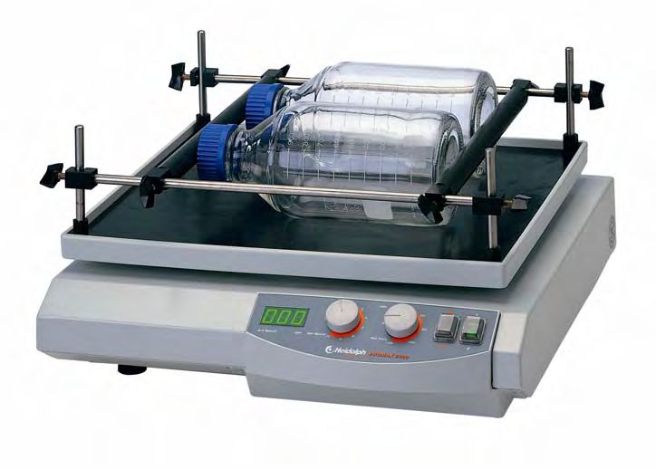
IDI     DEUTSCH      Seite    3 - 16

IEI      ENGLISH     page    17 - 30

IFi     FRANCAISE    page    31 - 44

lESI    ESPAGNOL    página   45 - 58

IlIlI   ITALIANO    Pagina   59 - 72
IEI
Thank you for purchasing a Heidolph Instruments product. This item has been designed,
made and inspected in compliance with DIN EN ISO 61010 for long-term and flawless
operation.

                                                           SUMMARY

Summary............................................................................................................       17
Standard hardware & options.............................................................................                  18
General...............................................................................................................    19
Safety information...............................................................................................         19
Set-up.................................................................................................................   20
1. machine set-up ............................................................................................            20
2. electric hook-up ...........................................................................................           20
3. load vessels on vibrator table ......................................................................                  20
   3.1. universal mount with base frame and clamping rollers ........................                                     20
   3.2. rack with clips .......................................................................................           21
   3.3. rack for separating funnel......................................................................                  22
   3.4. multi-level set-up...................................................................................             23
Operation and controls.......................................................................................             24
Cleaning & servicing...........................................................................................           25
Disassembly & storage.......................................................................................              26
Disposal..............................................................................................................    26
Troubleshooting.........................................................................................                  26
Specifications.....................................................................................................       27
• UNIMAX 2010...............................................................................................              27
• PROMAX 2020.............................................................................................                28
• POLYMAX 2040...........................................................................................                 28
Warranty, liability & copyright.............................................................................              29
FAQ / repair work...............................................................................................          29
CE-declaration of conformity..............................................................................                30

              Important information

              Advice about power cord / mains supply

              Caution: mandatory action

              Caution: fire- and explosion hazard

              Advice about maintenance / repair

                                                                         17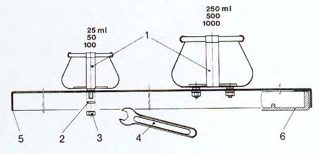
IEI
                        STANDARD HARDWARE & OPTIONS
           product                            quantity P/N              P/N
                                                       230/240V 50/60Hz 115V 50/60Hz

           Shakers / Mixers

           UNIMAX 2010                           1      542-10020-00    542-10020-01
      or   PROMAX 2020                           1      542-20020-00    542-20020-01
      or   POLYMAX 2040                          1      542-40005-00    542-40005-01
           (5° tilt)
      or   POLYMAX 2040                          1      542-40010-00    542-40010-01
           (10° tilt)
           Instruction Manual                    1      01-005-002-31   01-005-002-31
           Power cord                            1      14-007-003-81   14-007-003-89

           Accessories

           product                                                      P/N
           base frame                                                   549-50000-00
           clamping roller                                              549-58000-00
           universal tray                                               549-59000-00
           clamp for 25 ml Erlenmeyer flask                             549-51000-00
           (36 ea. per tray)
           clamp for 50 ml Erlenmeyer flask                             549-52000-00
           (36 ea. per tray)
           clamp for 100 ml Erlenmeyer flask                            549-53000-00
           (23 ea. per tray)
           clamp for 250 ml Erlenmeyer flask                            549-54000-00
           (12 ea. per tray)
           clamp for 500 ml Erlenmeyer flask                            549-55000-00
           (9 ea. per tray)
           clamp for 1000 ml Erlenmeyer flask                           549-56000-00
           (5 ea. per tray)
           holder for separating funnel 250 ml, 500 ml, 1000 ml         549-57000-00
           holder for separating funnel 2000 ml                         549-61000-00
           hardware for multi-level set-up                              549-60000-00

                                                  18
IEI
GENERAL
Unpack your item carefully.
Inspect for damage and report such damage or missing parts to your supplier right
away.
Read your Instruction Manual carefully. Take time to save time while working with
your product. Make sure that every user has read and understood the Instruction
Manual.
Please store the Instruction Manual in a place easily accessible to every user.
IF ALL ELSE FAILS, READ THESE INSTRUCTIONS !
A so-called EURO-plug (DIN 49441 CEE 7/VII 10/ 16 A 250 V) is standard on all of
the products.
For the Continental US they feature a US-standard plug (NEMA Pub.No.WDI.1961
ASA C 73.1 . 1961 page 8 15A 125V).
For using the item in a country with deviating outlet / plug systems, we recommend
to use approved adapters or to have an electrician replace the standard plug with
one mating your local system.
As shipped, the item features a protective ground wire. When replacing the original
plug, make sure to reconnect this protective ground wire in the new plug !
SAFETY INFORMATION
Please comply with all safety and accident-prevention regulations as in force
for laboratory work!
Use extra care when working with flammable substances; refer to safety data
sheets.
Use extra care when working in the vicinity of flammable and explosive
substances. Motors are of non-sparking type, the item itself however is not
explosion-proof.
When connecting your item with your local power supply, please make sure
your item is wired for your local voltage; refer to data plate on the item.
Please connect your unit with a protective-ground outlet only.
Repair work is limited to technicians approved by Heidolph Instruments.
Your item needs a solid stand.
Lab bench needs to be of rigid design, and features an anti-skid surface coat.
19IEI
Before starting the item, make sure all vessels are attached safely
(must not move while shaking).
SET-UP
1. Set-up
Please locate the shaker on a rigid, horizontal surface. For safety reasons, keep the area
around the machine clear of other items.
Be aware of orbital movement of the shaker plate and vessel set-up protruding over the
standard table surface.
2. Electric hook-up
Use the power cord from your hardware bag and connect it with the plug connector in the
item's rear panel.
The item features two-pole circuit breakers located in the item's plug connector for ease of
access. For circuit breaker details refer to data plate.
3. Secure vessels on shaker plate
To secure vessels on shaker plate, use optional adapters. Adapters for Erlenmeyer
flasks, separating funnels and a universal adapter with clamping rollers are available. For
more details refer to standard equipment and options.
In some cases using low shaking speed, vessels like Petri dishes just may be put on the anti-
skid rubber plate that comes with the item as a standard option.
Before starting shaking, make sure all vessels are secured in place properly.
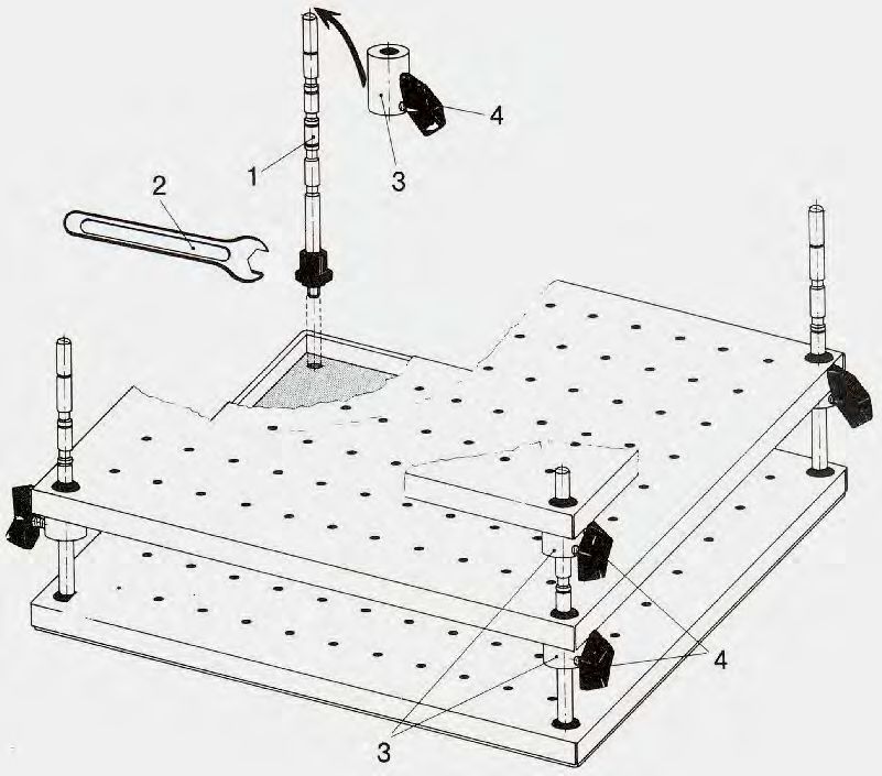
3.1. Universal mount with base frame and clamping rollers.
Base frame and clamping rollers allow to safely attach whatever sort of vessels and racks on
the shaker plate.
base frame (P/N 549-50000-00)
clamping roller (P/N 549-58000-00) 2 ea. minimum
The base frame goes on the shaker plate as described below:
Remove round rubber caps located in the four corners.
Thread 4 ea. bolts (1) in the respective holes and pull tight with box-end spanner (2) from
hardware bag. Slip holding bar (3) over bolts (1) and secure with wingbolts (5).
20IEI
Slip clamping rollers over holding bars (3), push against the vessel to be clamped, and
secure with wingbolts (5).
clamping roller
(P/N 549-58000-00)
base frame
(P/N 549-50000-00)
Attaching one more row of vessels requires installation of extra clamping rollers.
Before starting shaking, make sure all vessels and clamping rollers are safely locked
in place and all screws of the universal mount have been pulled tight as specified.
3.2. Rack and holding clamps for Erlenmeyer flasks
This rack with appropriate clamps allows to safely hold Erlenmeyer flasks of even different
sizes on the shaker plate.
Components: rack, P/N 549.59000.00 plus clamps (quantity as required):
• for 25 ml Erlenmeyer flask max. 36 ea. per rack, P/N 549.51000.00
• for 50 ml Erlenmeyer flask max. 36 ea. per rack, P/N 549.52000.00
• for 100 ml Erlenmeyer flask max. 23 ea. per rack, P/N 549.53000.00
• for 250 ml Erlenmeyer flask max. 12 ea. per rack, P/N 549.54000.00
• for 500 ml Erlenmeyer flask max. 9 ea. per rack, P/N 549.55000.00
• for 1000 ml Erlenmeyer flask max. 5 ea. per rack, P/N 549.56000.00
Distribution of holes in the rack permits whatever combination of clamps.
The only restriction is to arrange clamps in a manner avoiding direct contact between each
other; moreover, flasks should not protrude over the edge of the shaker plate.
How to install clamps:
• Remove nuts (3) and washers (2) from clamp bolts (1).
• Plug clamp (1) in rack hole and secure with washer (2) and nuts (3); tighten with box-end
spanner (4) from hardware bag.
• 25 to 100 ml clamps feature a threaded bolt, whereas 250 - 1000 ml clamps use four each
bolts.
Locate rack with clamps installed on shaker plate.
21IEI
Make sure, crimped edge (5) is plugged over shaker plate (6), thus positively locking both
parts with each other.
rack
(P/N 549-59000-00)
clamp for Erlenmeyer
flask
(P/N: refer to parts list)
Install Erlenmeyer flasks in holders:
Lightly tilt Erlenmeyer flasks to fit them under the clamp.
Before starting shaking, double check Erlenmeyer flasks for proper seat in their
clamps and all screws have been pulled tight.
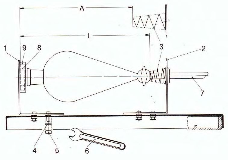
3.3. Rack and holder for separating funnels
Rack and separating funnel holder safely hold size 250 ml, 500 ml, 1000 ml or 2000 ml
separating funnels on the shaker plate.
Components: rack, P/N 549.59000.00 and separating funnel holders (as required):
• holder for size 1 (250, 500 or 1000 ml) separating funnels, P/N 549.57000.00
• holder for size 2 (2000 ml) separating funnels, P/N 549.61000.00
One rack accepts the following number of separating funnel holders: 4 ea. 250 ml,
3 ea. 500 ml, 3 ea. 1000 ml or 2 ea. 2000 ml; a mix of various sizes may be used either.
Install holders:
separating funnel holder
(P/N 549-57000-00)
(P/N 549-62000-00)
rack
(P/N 549-59000-00)
• Remove nuts (5) and washers (4) from part (1) & (2) bolts.
• Plug part (1) and part (2) into the rack's holes, so that dimension "A" is about 25 mm less
than length "L" of the separating funnel; as to guarantee proper clamping of the separating
22IEI
funnel and its closing plug by means of compression spring (3). Dimension "A" once set
will be good for one and the same size of separating funnel only. Whenever using a
different model of separating funnel, you need to check dimension "A" and readjust
accordingly.
• Install washer (4) and nuts (5) on bolts of parts (1) and (2); pull tight with box-end spanner
(6) from your hardware bag.
Locate rack with holders on shaker plate.
Make sure, crimped edge (10) is plugged over the shaker plate (11), so positively locking both
parts with each other.
Install separating funnel:
Install separating funnel with its outlet pipe (7) first through compression spring (3); press item
against compression spring (3) until closing plug (8) kocks with retainer ring (9).
Before starting shaking, make sure that the outlet pipes (7) of your separating
funnels are clear of other items on your lab bench. Maintain sufficient space
between separating funnels to avoid a collision situation.
3.4. Hardware for multi-level set-up
This hardware allows installation of a second or third rack plate for Erlenmeyer flasks on the
shaker plate.
Using 25 ml Erlenmeyer flasks, a total of 3 racks may be set-up the same time, whereas 50
ml to 250 ml Erlenmeyer flasks may be arranged on 2 only racks.
Components: installation hardware for multi-level set-up, P/N 549.60000.00;
extra racks with clamps for Erlenmeyer flasks, as described under para. 3.2.
Set-up:
Please pay attention to the position:
wingbolt (on clamping sleeve)
D situated below
Pos 4: wingbolts must
be adjusted vertically to
C
the outer edge of the
4 platform
B
3
1 A
23IEI
Install 4 ea. columns (1) and pull tight with box-end spanner (6) from your hardware bag.
Locate first rack panel over columns. Slip 4 ea. clamping sleeves (3) over column (1) and
secure with wingbolt (4) (wingbolts must be adjusted vertically to the outer edge of the
platform).
Column (1) features vor marks for clamping sleeve (3) offest A, B, C and 3D.
3 ea. racks for 25 ml Erlenmeyer flask: A & D marks
2 ea. racks for 50 ml Erlenmeyer flasks: B mark
2 ea. racks for 100 ml Erlenmeyer flasks: C mark
2 ea. racks for 250 ml Erlenmeyer flasks: D mark
Install second rack over column (1) and seat on clamping sleeve (3).
Install 3rd rack (if required) by repeating above steps.
Before starting shaking, make sure all vessels are securely held by their clamping
brackets and all bolts have been pulled tight.
OPERATION AND CONTROLS
Before connecting power cord with mains outlet, make sure that:
- your item is wired for your local voltage and frequency (data plate on
item).
- master switch is set to "0" and all controls are in "min." position (turn
CCW completely); this way you avoid spilling fluids by too intense
shaking action.
Carefully close your vessels and select appropiate shaking intensity (if
flasks remain opern) to avoid splashes and spillage.
We recommend starting with low shaking speed and gradually increase
frequency to avoid accidential shaking at high speed.
On principle, one single flask should be arranged in the middle of the
shaker plate, whereas more flasks should be distributed equally on the
plate.
At high loads (load-bearing capacity of shaker plate) and high frequency
of shaking, always make reference to load graph as aplicable for your
item (refer to "Specifications" section).
When handling hazardous fluids, make reference to applicable safety
information.
24IEI
The control panel features the following controls (from right to left):
E D C B A
A 2-pole master switch (toggle-type, lighted green)
B continuous / timer-control selector
C timer setting knob
D speed selector knob
E 3-digit speed display
1. Turn item ON with master switch (A).
2. Select speed with speed selector (D).
3. Select continuous / timer controlled operation with selector (B) (symbol () or timer
control (timer). In the timer mode, shaking action can be selected between 0 and 120
minutes; the timer will continue running even in absence of power suppy.
4. Actual speed appears in the 3-digit digital display.
When using shakers inside conditioning cabinets, make reference to
ambient conditions as stipulated in the "Specifications" Section).
CLEANING & SERVICING
Cleaning: wipe housing clean with a damp cloth (add some sort of mild liquid soap).
Note
To avoid damage to the surface finish, avoid using chlorine bleach, chlorine-
based detergents, abrasive substances, ammonia, rags or cleaning agents
containing metal particles.
The item is maintenance-free. Repair work is limited to technicians so approved or appointed
by Heidolph Instruments. Please call your local Heidolph Instruments Dealer or a Heidolph
Instruments Field Representative (also refer to page 29)
25IEI
DISASSEMBLY & STORAGE
Disassembly
1. Turn item OFF and diconnect mains plug.
2. Remove all of the hardware arranged around the shaker to ease disassembly.
3. Unload all flasks from shaker, uninstall optional equipment.
Forward & Store
1. We recommend to store the item and its components in its original box, or a similar
container that guarantees adequate protection against damage in transit. Tape the box
securely.
2. Store the item in a dry place.
Caution
Do not jolt or shake the item during transport.
DISPOSAL
For disposal, please comply with your local or national regulations.
Split by metal, plastic, etc.
Packing material to be treated as described above (material split).
TROUBLESHOOTING
Work on electric, electronic and cryogenic components is limited to qualified personnel.
Master switch on shaker / mixer won't light
1. Check power cord
2. Check circuit breakers
Item won't shake (master switch lighted))
1. Timer run-down
2. Thermal motor circuit breaker triggered by motor overload
Remedy:
Wait about 20 minutes, decrease load applied on shaker plate.
3. Mechanical parts broken (humming motor noise) or electronic failure (no motor noise).
26IEI
SPECIFICATIONS
all shakers
space required 415 x 455 mm
weight of item abt. 15 kg
ambient temperature 0°C to 50°C at 80% rel. humidity
approved for installation in gassing and conditioning cabinets
(make reference to temperature limits)
power dissipation 66 W
voltage / frequency 230/240V 50/60Hz; 115V 50/60Hz optional
protective class IP 20
power source condenser motor, electronic speed control
UNIMAX 2010
shaker frequency 20 – 400 1/min
total stroke / orbit 20 mm
motion type rotating
load-bearing capacity static: 10 kg; less at high shaking frequency
timer 0 – 120 minute timer / continuous operation
shaker plate 390 mm x 340 mm
features anti-skid rubber coating
- When running at high shaking frequency, make reference to graph for decrease
in load-bearing capacity of shaker plate.
Load UNIMAX 2010, load admissible undue
(kg) range
10,0
8,0
6,0
4,0
2,0
0,0
0 100 200 300 400
Shaking frequency (1/min)
27IEI
PROMAX 2020
shaker frequency 20 – 400 1/min
total stroke / orbit 20 mm
motion type reciprocal
load bearing capacity static: 10 kg; less at high shaking frequency
timer 0 – 120 minute timer / continuous operation
shaker plate 390 mm x 340 mm
features anti-skid rubber coating
- When running at high shaking frequency, make reference to graph for decrease
in load bearing capacity of shaker plate.
Load PROMAX 2020, load admissible undue range
(kg)
10,0
8,0
6,0
4,0
2,0
0,0
0 100 200 300 400
Shaking frequency (1/min)
POLYMAX 2040
shaker frequency 2,5 – 50 1/min
angle 5 / 10°
motion type rocking
load-bearing capacity static: 10 kg; less at high shaking frequency
timer 0 – 120 minute timer / continuous operation
shaker plate 390 mm x 340 mm
features anti-skid rubber coating
- When running at high shaking frequency, make reference to graph for decrease
in load bearing capacity of shaker plate.
Load POLYMAX 2040, undue range
(kg) eccentric load admissible
10,0
8,0
6,0
4,0
2,0
0,0
15 45 75 105 135
C&G offset (mm)
28IEI
WARRANTY, LIABILITY & COPYRIGHT
Warranty
Heidolph Instruments guarantees that the present product shall be free of defects in material
(except wear parts) and workmanship for 3 years from the date shipped off the
manufacturer’s warehouse.
Damage in transit is excluded from this warranty.
To obtain such warranty service, contact Heidolph Instruments (phone:++49-9122-9920-68)
or your local Heidolph Instruments Dealer. If defects in material or workmanship are found,
your item will be repaired or replaced at no charge.
Misuse, abuse, neglect or improper installation are not covered by this warranty.
Alterations to the present warranty need Heidolph Instruments’ consent in writing.
Exclusion Clause
Heidolph Instruments cannot be held liable for damage from improper use or misuse.
Remedy for consequential damage is excluded.
Copyright
Copyright in pictures and wording of the present Instruction Manual is held by Heidolph
Instruments.
FAQ / REPAIR WORK
If any aspect of installation, operation or maintenance remains unanswered in the present
Manual, please contact the following address:
For repair work please call Heidolph Instruments after-sales service (phone:++49-9122-
9920-72) or your local, authorized Heidolph Instruments Dealer.
Note
You will receive approval for sending your defective item to the following address:
Heidolph Instruments GmbH & Co. KG
Lab Equipment Sales
Walpersdorfer Str. 12
D-91126 Schwabach / Germany
phone: ++49–9122-9920-68
Fax: ++49–9122-9920-65
E-Mail: Sales@Heidolph.de
Note
If you are based in the United States of America, please contact Heidolph US :
Heidolph Instruments, LLC
Lab Equipment Sales
2615 River Rd.
Cinnaminson, NJ 08077
Phone: 856-829-6160
Fax: 856-829-7639
E-Mail: heidolph@snip.net
29IEI
Safety Information
When shipping items for repair that may have been contaminated by hazardous
substances, please:
- advise exact substance
- take proper protective action to ensure the safety of our receiving and service
personnel
- mark the pack IAW Hazardous Materials Act
CE-DECLARATION OF CONFORMITY
We herewith declare that the present product complies with the following standards and
harmonized documents:
EMC-guideline (89/336/EWG):
EN 61326: 1997 + A1:1998 + A2:2001 + A3:2003
EN 61000-3-2: 2000
EN 61000-3-3: 1997 + A1 2001
EN 61326: 1997 + A1:1998 + A2:2001 + A3:2003
EN 61000-4-2:1995 + A1:1998 + A2:2001
EN 61000-4-3:2002 + A1:2002
EN 61000-4-4:1995 + A1:2001 + A2001
EN 61000-4-5:1995 + A1:2001
EN 61000-4-6:1996 + A1:2001
EN 61000-4-11:1994 + A1:2001
Low-voltage guideline (73/23/EWG):
EN 61010
EN 61010-2-051
30IIIII
Avvertenze di sicurezza
Nel caso in cui sia necessario spedire un apparecchio che deve essere riparato e
che è stato a contatto con sostanze pericolose, si raccomanda di:
- Fornire indicazioni quanto più precise sulle sostanze che compongono il mezzo
in questione
- Prendere le dovute misure di sicurezza per garantire l’incolumità del nostro
personale addetto al ricevimento merce e alla manutenzione.
- Contrassegnare l’imballo conformemente alla normativa sulle sostanze nocive
DICHIARAZIONE DI CONFORMITÀ CE
Dichiariamo che il presente prodotto è conforme alle seguenti norme e documenti normativi:
Direttiva CEM (89/336/EWG):
EN 61326: 1997 + A1:1998 + A2:2001 + A3:2003
EN 61000-3-2: 2000
EN 61000-3-3: 1997 + A1 2001
EN 61326: 1997 + A1:1998 + A2:2001 + A3:2003
EN 61000-4-2:1995 + A1:1998 + A2:2001
EN 61000-4-3:2002 + A1:2002
EN 61000-4-4:1995 + A1:2001 + A2001
EN 61000-4-5:1995 + A1:2001
EN 61000-4-6:1996 + A1:2001
EN 61000-4-11:1994 + A1:2001
Direttiva sulla bassa tensione (73/23/EWG):
EN 61010
EN 61010-2-051
01-005-002-31-0 15.02.2006
© HEIDOLPH INSTRUMENTS GMBH & CO KG
Technische Änderungen sind ohne vorherige Ankündigung vorbehalten.
We reserve the right to make technical changes without prior announcement.
Sous réserve de modifications techniques sans avis préalable.
Se reserva el derecho de realizar modificaciones téchnicas sin previo aviso.
Ci riserviamo il diritto di apportare modifiche tecniche senza alcun preavviso.
72You can also read