A DYNAMIC MODEL AND ANALYSIS OF INNOVATIVE E-BIKE - IRJET
←
→
Page content transcription
If your browser does not render page correctly, please read the page content below
International Research Journal of Engineering and Technology (IRJET) e-ISSN: 2395-0056
Volume: 07 Issue: 04 | Apr 2020 www.irjet.net p-ISSN: 2395-0072
A DYNAMIC MODEL AND ANALYSIS OF INNOVATIVE E-BIKE
Aman sharma1, Manish K Sah2, Abhishek kumar3, Umesh K Yadav4
1,2,3Student
Dept. of mechanical Engineering, MGM College of Engineering & Technology Noida,
Uttar Pradesh, India
4Asst Professor Dept. of mechanical Engineering, MGM College of Engineering & Technology Noida,
Uttar Pradesh, India.
----------------------------------------------------------------------***-------------------------------------------------------------------
ABSTRACT-The E- Bike model has an innovative and demand and second is pedal assist. The motor is
significant number of new features that improve the user activated by a throttle with as per power-on-demand. By
experience through an adequate position of motor. The pedalling electric motor can be controlled with pedal-
addition of new functions such as the spring shock assist. The charging mechanism of this bike is done with
absorber, mosfet circuit and shimano 7 gear drives dynamo and mosfet circuit. E-bike will be reduce traffics,
mechanism used. The design and analysis of new type of e- air pollution, greenhouse effect and parking problem in
bike frame which is look alike of mountaineer bike frame the fast growing population.
with consideration of an aerodynamic effect. We have
design a 4-bar linkage spring mechanism with attached LITERATURE REVIEW
the rear frame for absorbing the shock and vibrations. The
E-bike which is able to recharge itself during travelling or In this research paper Chang-hua et.al [1] done a bi-
riding it, so that the number of motor vehicle on the road directional converter applied in electric bike. The main
get decreased hence the dependency of Non-renewable structure is a cascade buck-boost converter, which
fuel energy resources also get decreased. The problem transfers the energy stored in battery for driving motor,
which have been arising like air pollution and greenhouse and can recycle the energy resulted from the back
effect get down which will improve the health condition of electromotive force to charge battery by changing the
people. Also provide for safe and convenient access to operation mode. An e-bike design Meireles et.al [2] The
schools, parks, natural areas and community facilities. fourth-generation bike-sharing services. Bicycle sharing
systems have proven their value towards urban
Keywords: Motor drive, MOSFET, Shimano7, Mobility, sustainable mobility. Appropriate design of bikes for this
Linkage spring mechanism application is fundamental for bike-sharing systems
viability. Malan et.al [3] the design and development of a
1. INTRODUCTION prototype super-capacitor powered electric bicycle (e-
bike) is presented. The design of bicycles is concentrated
The e-bike can be effective to reduce the usage of cars, Zhang et.al [4] on mechanism and auto appearance
motor bike because people try to move toward 'clean' design, however few on matches between the bike and
the global environment effects. Additionally, e-bike the rider. Since unreasonable human-bike relationship
resolve many people give for not cycling like hills, long leads to both riders’ worn-out joints and muscle injuries,
route, and physical strenuousness. The e-bike which is the design of bicycles should focus on the matching. In
design an inexpensive and auto rechargeable electric order to find the best position of human-bike system,
bike. E-bike solve the problem, which is facing the simulation experiments on riding comfort under
cycling on long routes, hills and physical level. Electric different riding postures are done with the life mode
bike is powered by a rechargeable battery which gives software employed to facilitate the cycling process as
rider an extra boost of power and less cycling well as to obtain the best position and the size function
experience. E-bike as compare to normal bike it has got of it. Hatwar et.al [5] design electric bike using battery
an electric motor to assist or replace your peddling effort and super capacitor, the market of electric bikes,
and motor can be activated by pressing button with scooters and bicycles is growing. There are numerous
activating the accelerator. Automobile Industry in data brands of e-bike emerging locally. All incorporate a rear
processing and cloud connectivity technology that are wheel bldc (brushless dc) hub motor; lead acid battery
fundamental in establishing to connected vehicle system. pack, a light weight chassis, and a controller. The vehicle
We are used to develop models using sensors like achieves average speed of 30-50km/hr, range of 70km
speedometer, odometer and accelerometer whose data charge. The other drawback is the long charging time of
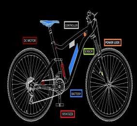
is displayed in the database file. Typical parts of E-bike 6-8 hrs and short lifespan of battery pack i.e. around 2
are DC Motor with sprocket drive mechanism, Throttle years.Abagnale et.al [6] model is based on the
(Accelerator), Battery Storage, Chain Drive, sprocket longitudinal vehicle dynamic and the electrical motor.
drive, four bar linkage spring mechanism, development Kunjan Shinde [7] design of electric bike and sprocket or
of aerodynamic Frame. According to their functions of e- chain mechanism for electric bike. Most number of
bike, electric bicycle has two parts, first is power on people from the list have been those which think riding a
© 2020, IRJET | Impact Factor value: 7.34 | ISO 9001:2008 Certified Journal | Page 628International Research Journal of Engineering and Technology (IRJET) e-ISSN: 2395-0056
Volume: 07 Issue: 04 | Apr 2020 www.irjet.net p-ISSN: 2395-0072
cycle is equivalent to providing extra effort for cycling. Following Stresses are taken in consideration while
Mei et.al [8] analysed e-bike usage and battery charging designing the shaft:
data from the bike field trial. By design, e-bikes were Material = C 45 (mild steel)
meant to be used for commuting, potentially replacing σut = 320 N/mm2 ------------ PSG design data book.
the use of cars or public transit. Zingnoli et.al [9] to Factor of safety = 1.4
control the strategies of electric-bikes do not take the σt = σb = σut / fos
physiological characteristics e.g. aerobic fitness status of 2
the rider into account. By means of mathematical = 320/1.4= 228.57 N/mm
modelling done. Katoch et.al [10] developed the σs = 0.5 σt
implementation of smart electric-bike eco-friendly with = 0.5 x 228.57
the using hub motor with self-recharging mechanism 2
= 114.285 N/mm
using the hybrid system and maximum current drawn
σs is less then allowable so our shaft design is safe.
from the cycle at two stages.
2. DESIGN OF ELECTRIC BIKE 2.3 Analysis of sprocket and chain
2.1 ANALYSIS OF ELECTRIC BIKE
We have known that,
For Pedal calculation Transmission ratio = Z2 / Z1 = 54/14 = 3.82
Pedal power = pedal force * pedal speed in m/s For the above transmission ratio number of teeth on
=25 kg * 9.8 m/s2 * 1 m/s pinion and the number of teeth sprocket is in the range
= 245 watt of 21 to 10, so we have to select number of teeth on
Taking the rider in travelling cycle at 15 km/h pinion sprocket as 14 teeth.
15000m/60 min = 250 m/min So, Z1 = 14 teeth
Wheel rotation/Rpm = distance in 1 min/wheel
perimeter 2.4 Selection of pitch of sprocket
= 250/ 2.07345
= 120.57 rpm The pitch is decided on the basis of RPM of sprocket.
Wheel Rpm when pedalling at 15 km/h is 120.57 rpm. RPM of pinion sprocket is variable in normal condition it
Teeth on pedal (T1) = 54 is = 270 Rpm For this rpm value we select pitch of
Teeth of sprocket at wheel (T2) = 14 sprocket as 6.35mm from table. P = 6.35mm
Wheel rpm (N2) = 120.57 rpm
From equation, N1 T1 = N2 T2 2.5 Analysis of minimum center distance between
N1 = (120.57* 14) / 54 sprocket
N1 = 31.2588 rpm
Pedal rpm (N1) = 31.26 rpm The transmission ratio = Z2 / Z1 = 54/14 = 3.82 (which
Hence, torque (T) = P*60/2 N is less than 7)
T = (245*60) / (2*3.14*31.26) Dia. of small sprocket,
T = 74880 N-mm. Periphery = π × dia. Of sprocket
Reduction at chain drive 14 × 6.25*2 = π × D1
= T1/T2 = 54/14 = 3.857 D1 = 53.50 mm
Torque at wheel shaft = T*R Dia. of big sprocket,
= 74880* 3.857 = 288814.076 N-mm Periphery = π × dia. Of sprocket
Here we have used DC Gear motor with 250 Watt Power 54 × 6.25 = π × D2
and 270 Rpm. The motor runs on 24 Volts and 14 Amps D2 = 107.48 mm
Power source. This motor can reach a peak current So from table, referred from PSG Design Data book.
during starting equal to 15 Amps.
P = 2 x 3.14 x N x T /60 The minimum center distance between the two
250 = 2 x 3.14 x 270 x T /60 sprocket
Speed of wheel shaft = 270 /3.82 = 70.68rpm
= CI + (80 to 150 mm)
2.2 Analysis of Shaft Where,
CI = (Dc1 + Dc2)/2
Torque at wheel shaft T = 288814.076 N mm CI= (54 + 107.48)/2
3 CI = 80.74 mm
T=3.14xσs x d /16
σs = 288814.076 * 16 / 3.14*243 Minimum Centre Distance = 80.74 + (30 to 150 mm)
2 Minimum Centre Distance = 230 mm.
σs = 106.40 N/mm Maximum Centre Distance = 2*230 = 460 mm
© 2020, IRJET | Impact Factor value: 7.34 | ISO 9001:2008 Certified Journal | Page 629International Research Journal of Engineering and Technology (IRJET) e-ISSN: 2395-0056
Volume: 07 Issue: 04 | Apr 2020 www.irjet.net p-ISSN: 2395-0072
2.6 Maximum tension on chain. = 160.76 Rpm
To travel 30 km in 1 hr so, Wheel rotation = distance in
Maximum torque on shaft = Tmax = T = 288814.076 N- minute / wheel perimeter
mm = 500/2.03745 = 241.14 rpm.
Where, But at 270 rpm the distance covered will be
T1 = Tension in tight side 270 = distance in mm/perimeter
T2 = Tension in slack side 270*2.07345 = distance in mm
Distance in mm =559.83 m/min
O1, O2 = centre distance between two shaft
Distance in km hour = (559.83* 60)/1000
Sin = (R1 -R2)/O1O2 Distance = 33.58 km in one hour.
Sin = (115 - 54)/460
Sin = 0.132 2.8 Motor sprocket v/s wheel sprocket
= 7.62
Angle of contact between the front and rear sprocket. For the gear ratio
= (180 –2 ) X 3.14/180 Wheel sprocket teeth =18
= (180 –2*7.62) X 3.14/180 Motor sprocket teeth =9
= 2.87 rad. Gear ratio =18/9 = 2:1
According to this relation, The rpm of motor at 270 only provide 270/2
= 135rpm at wheel
T1/T2 = e
So, max rpm of motor the wheel rpm is 135.
0.35 x 2.87
T1/T2 = e Then, distance covered in 1 min = RPM * 2.07345
T1 = 2.74*T2 = 279.91 m/min. or. 279.91*60/1000 = 16.794 km/hr.
We have, So, max speed is 16.79 km/hr on road.
T = (T1 – T2) X R
288814.076= (2.74* T2 – T2) X 115 Table 1.1 Dimension of E-bike
T2 = 1443.34 N-mm
S.no Part name Dimension
T1 = 3954.77 N-mm
1 Top Tube L=650mm,
2.7 Battery charging time. =15
2 Seat Tube L=420mm
Motor Rating 3 Down Tube L=675mm,
24*10.416 = 250 Watt =15 & 25
Battery Rating 4 Head Tube L=130mm
24*14 = 336 Watt
5 Seat Stay L=360mm
As per value is 1 km travel will be cost up-to
1 km = 15 watt 6 Chain Stay L=490mm
So, full charge battery will run 7 Min Center 230mm
Distance = 336/15 = 22.4 km. Distance b/w Two
Distance cover with full charge at any speed of 20 kmph Shaft
on flat road is 22.4 km. 8 Max Center 460mm
To charge the battery a dynamo of rotating 12 v .5 amp Distance b/w Two
dynamo, if generally it will produce a 12*0.5 = 6 watt of Shaft
power, at constant speed of 20 kmph running bicycle. So 9 Distance Covered 22.4 Km
fully charge the battery we need to run the bicycle @20Km/Hr
Distance = 3.36/6 = 56 km.
We need to run the bicycle for 56 km at 20 kmph to fully
3. MODELLING OF E-BIKE
charge the batter. But as per to the average running
bicycle by a man is 7 to 10 kmph it will generate 2-3
We have use the Solid-works and Q-CAD software for the
watt, say 2.4 watt So that at the speed of 7 –10 kmph the
modelling of e-bike. Q-CAD is a commercial computer-
distance that to be run by the person is:
aided design and drafting software application. Q-CAD
Distance = 336/24 = 140km.
software which is used for 2D designing of various object
like auto mobile and many other parts. Modelling of
Speed
electric bike (affordable electric bike) was done by Q-
CAD software considering the design value. The E-Bike
Taking 20 km/h travelling so the rotation of wheel
modelling of various parts as per design which is given
Wheel rotation = distance in minute/wheel perimeter
below.
= (333.33)/ ( *0.66)
= 333.33/2.07345
© 2020, IRJET | Impact Factor value: 7.34 | ISO 9001:2008 Certified Journal | Page 630International Research Journal of Engineering and Technology (IRJET) e-ISSN: 2395-0056
Volume: 07 Issue: 04 | Apr 2020 www.irjet.net p-ISSN: 2395-0072
3.1 Modelling of E-Bike frame 3.1.2 Modelling of down tube
The down tube connects the head tube to the bottom
We have used the Solid-works software for the bracket shell. Down tube is joined to the head tube and
modelling of E-bike frame as shown in fig.1.1 Solid works side tube and the length is 675 mm or bend angle is one
software is a solid modelling CAD and CAE computer side 25 degree and other side is 15 degree shown in fig
program software that runs on Microsoft window while 1.3.
it is widely used for product design and assembly. Solid
works which is used for designing of various object like
auto mobile and many other parts. Modelling of electric
bike (affordable electric bike) was done by solid works
software considering the design value which is include
the front and rear frame.
Fig 1.3 Down tube
3.1.3 Modelling of seat tube
The seat tube contains the seat post of the bike, which
connects to the saddle shown in fig 1.4. Seat tube is
joined to the top tube and down tube, seat tube length is
420 mm and width is 25 mm. The saddle height is
adjustable by changing how far the seat post is inserted
into the seat tube.
Fig 1.4 side tube
Fig.1.1 Modelling of E-Bike front and rear frame. 3.1.4 Head tube length
The head tube contains the headset, the bearings for the
3.1.1 Modelling of top tube fork via its steered tube shown in fig 1.5. In an integrated
The top tube or cross-bar connects the top of the head headset, cartridge bearings interface directly with the
tube to the top of the seat tube shown in fig 1.2. Bend surface on the inside of the head tube, on non-integrated
angle is 15 degree and length are 650 mm, the top tube is headsets the bearings in a cartridge or not interface with
sloped downward toward the seat tube. "cups" pressed into the head tube.
Fig 1.2 Top tube
© 2020, IRJET | Impact Factor value: 7.34 | ISO 9001:2008 Certified Journal | Page 631International Research Journal of Engineering and Technology (IRJET) e-ISSN: 2395-0056
Volume: 07 Issue: 04 | Apr 2020 www.irjet.net p-ISSN: 2395-0072
3.3 SPRING MECHANISM
It is a single pivot joint suspension design attached to the
seat tube. It is typically of four bar linkages on to which
the rear axle is attached. When there is a sudden shock
or jerk load is transferred to the down tube of the front
frame so that the Load is distribute as to wear the
sudden load. This makes the rear frame free to move in
up-down motion. The shocker spring length 185 mm and
the distance between the hinge point is 90 mm. The max
deflection/compression of the spring is 6.45 mm. By
fixing that position as shown in the fig 1.8. The jerk load
Fig 1.5 Head tube very effectively transfers by the hinge link to the shock
absorber spring.
3.1.5 Chain Stays
The chain stays run parallel to the chain and connected
the bottom bracket shell to the rear fork ends. We made
shorter chain stay so that the bike will accelerate faster
and be easier to ride uphill. According to the calculation
the length of chain stay is 490 mm shown in fig 1.6.
Fig 1.6 Head tube
3.1.6 Seat Stays
The seat stays connected to the top of the seat tube or
Fig.1.8 Linkage spring mechanism
3.4 SPROCKET MECHANISM
We have used the two-side sprocket mechanism in rear
wheel. One side is gear drive system and second side are
normal sprocket system which is connected to the motor
sprocket because motor sprocket mechanism is chain
near the same point as the top tube and to the rear fork transfers that rotation to the rear sprocket, which turns
ends. It is also used for attaching the rear brake calliper. the rear wheel, and the bicycle moves forward. When
The distance between the chain stay to the seat tube is you turn the pedals, the front sprocket turns. The chain
340 mm. transfers that rotation to the rear sprocket, which turns
the rear wheel, and the bicycle moves forward.
Fig 1.7 Seat stay Fig. 1.9 Sprocket with shimano 7 gear drive mechanism
© 2020, IRJET | Impact Factor value: 7.34 | ISO 9001:2008 Certified Journal | Page 632International Research Journal of Engineering and Technology (IRJET) e-ISSN: 2395-0056
Volume: 07 Issue: 04 | Apr 2020 www.irjet.net p-ISSN: 2395-0072
accelerator vehicle that used to
increase and decrease
speed.
3 Wire Throttle For
12V-48V.
13 Controller 1 Converts input power
of battery into the
desired power for the
different accessories.
14 Horn 1 Low sound horn 6v.
15 Suspension 2 Absorbing the shocks
from the uneven road.
Primary suspension
dual type (oil)
Secondary suspension
(spring).
16 Mud guard 1 set To stop mud, water
Fig. 1.10 Modelling of E-Bike
and gravel.
3.5 ACCESSORIES PART OF E-BIKE
4. RESULTS & DISCUSSION
The Electric bike consists of following components viz.,
1 Design of Frame
DC motor, Frame, Platform, Battery, Drive etc. The detail
parts with specification and quantity are given in table
The structure of E bike is made of hollow square
1.2.
rectangular pipe. E bike is differ from the other bike
because its design is like a aerodynamic which provide
Table 1.2 parts of E-bike
more speed with reducing the air resistance while
driving. The rear part of E bike is connected with hinge
S. Part Quantity Specification
point so that the jerk is transferred through seat stay to
No
shocker.
1 D.C motor 1 Power 250 W RPM
270, Air Cooled,
2 Shock Absorbing spring
14Amp 24v
2 Brakes 4 2 Sets power pads
Our electric bike can be divided into two part because
3 Battery 2 12v 7amp Lithium ion we had given a hinge connectivity. A four bar linkage
4 Alloys wheels 2 Wheel dia. 26inch suspension on the rear axle is attached when there is
Width 1.95 inch sudden load or Shock is transferred to the spring
5 Gears 1 7 Speed gear shimano shocker very effectively shown in fig 1.10.
for easy shifting
6 Frame 1 Made with mild steel, 3. Battery charging mechanism
light weight and good
durability. For self-charging the batteries we have used the dynamo
7 Speedometer 1 Magnetic attached with mosfet circuit for the charging while pedalling. The
reader for accurate Operating cost per/ km is very less with the help of
speed reading. recharging system. The charging system has fewer
8 Charger 1 1.8amp 24v Portable. components thus require less maintenance. The distance
9 Ignition 1 To activate the main cover with full charge battery at speed of 20 kmph on flat
switch electrical system for road is 22.4 km.
the vehicles.
10 Charging port 1 To recharge the Conclusion
battery easily.
3 pin Eu-plug. We have design and analysis of new type of e-bike frame
11 Head lamp 1 Attached to the front which look alike of mountaineer bike with consideration
portion of the vehicle of an aerodynamic effect. E-bike is a modification of the
to illuminate the road. current using bicycle. E-bike is powered with electric
IPX6 rated water energy. E-bike can be used by any age of people for
proof. shorter distance and it is cheap and affordable bike as a
12 Hand 1 Control unit of a new way of transportation with the uses of more Non-
© 2020, IRJET | Impact Factor value: 7.34 | ISO 9001:2008 Certified Journal | Page 633International Research Journal of Engineering and Technology (IRJET) e-ISSN: 2395-0056
Volume: 07 Issue: 04 | Apr 2020 www.irjet.net p-ISSN: 2395-0072
renewable fuel, it is required to use an alternate way of
saving the non-renewable fuel by introducing bike does
not require any non-renewable source of energy and
most important function of this e-bike. It is eco-friendly,
noiseless, pollution free, and provide comfortable in ride.
Based on detailed study the following conclusions have
been drawn:
1-The objective of a comfortable, compact, high speed
and efficient bicycle can be achieved by this dynamic
model.
2-Dynamic model of e bike with detail analysis of
different parts done.
3. It will reduce traffic and parking problems in this fast
growing population.
REFERENCES
1. Chang-Hua, Lin Hom-WeiLiu, Chien-Ming wang “A
design and implementation of a bi-directional converter
applied in electric bike with charging feature”
Proceedings of the 5th conference IEEE (2010) ISSN
2156-2318.
2. Ricardo Meireles, Jose Silva, Alexandre Teixeira,
Bernardo Ribeiro “An E-bike design for the fourth-
generation bike sharing service” World Electric Vehicle
Journal (2013)Vol. 6 - ISSN 2032-6653.
3. Keagan Malan , Michael Coutlakis , James Braid
“Design and development of a prototype super-capacitor
powered electric bicycle” IEEE International Energy
Conference (2014) ISBN 978-1-4799-2449-3.
4. Long Zhang, Zhongxia Xiang, Huan Luo, Guan Tian
“Test verification and design of the bicycle frame
parameters” Journal of Mechanical Engineering
CJME(2015) Corpus ID 56228079.
5.Nikhil Hatwar, Anurag Bisen, Haren Dodke, Akshay
Junghare, Milind Khanapurkar “The design approach for
electric bikes using battery and super capacitor, for
performance improvement” IEEE Conference (ITSC
2013) ISSN 2153-0017.
6. C. Abagnalea, M. Cardoneb, P. Iodicea, R. Marialtoc, S.
Stranoa, M. Terzoa, G. Vorraro “Design and development
of an innovative e-bike” Energy Procedia (2016) 101 774
– 781.
7. Kunjan shinde “Literature Review on electric bike”
IJRMET (2017) vol.7 ISSN 2249-5762.
8. Huan Mei, Yang xiaobao, jia bin “Crossing realibility of
electric bike riders at Urban intersections” Green
transportation system and safety, (2013)ISSN 1024-
123X .
9. Andrea Zignoli, Lorenzo Beatrici , Francesco Biral
“Analysis of assistive strategies for electric bikes that
include riders physiological characteristics” ASME-
85288, (2018) V003T01A012.
10. Sunikshita Katoch, Rahul, Ranjit Kumar
Bindal”Design and implementation of smart electric bike
eco-friendly, IJITEE (2019) Vol.8 ISSN 2278-3075.
© 2020, IRJET | Impact Factor value: 7.34 | ISO 9001:2008 Certified Journal | Page 634You can also read