NISSAN R35 GTR TRANSMISSION COOLER INSTALLATION
←
→
Page content transcription
If your browser does not render page correctly, please read the page content below
NISSAN R35 GTR TRANSMISSION COOLER
                 INSTALLATION

Tools needed:
2 or 4 post garage lift
Small and large flat bladed screwdriver
10mm,12mm and 13mm sockets, long extension, 3/8 or ¼” ratchet
22mm spanner
PTFE tape
Loctite
12 litres of transmission fluid
4mm,5mm and 7mm allen sockets
Side cutters/wire cutters
Soldering iron and solder
Electrical tape
M6 tap
5mm,7mm,8mm and 9mm drill bits with suitable drill
Side cutters
Wire strippers and crimpers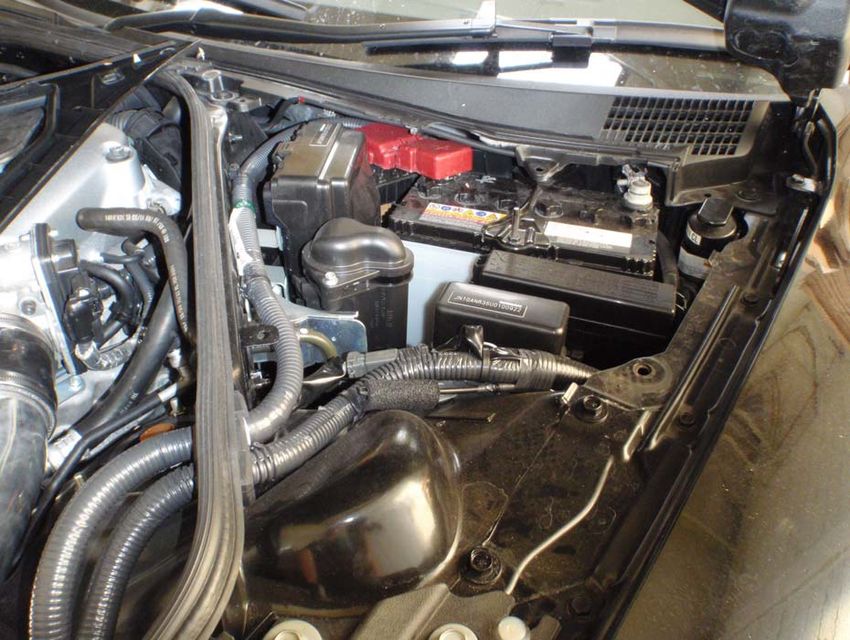
Kit contents:
Please check your kit carefully, though it will be time consuming, to ensure you have everything before you start.

1x Aluminium sump
1x Genuine Nissan sump gasket
1x Electrical harness
1x Brass temp sensor
1x M14 bonded seal
1x M16x1.5 to ‐8JIC adaptor
1x M16 bonded seal
1x M18x1.5 to ‐8JIC adaptor
1x M18 bonded seal
1x 25 row oil cooler
1x Mocal oil pump
1x 3/8NPTF to ‐8JIC adaptor
1x 3/8NPTF to ‐8JIC adaptor 45 degree
6x 19mm P‐clip
1x 16mm P‐clip
6x aluminium fabricated brackets
3x special assembled hoses (2 are heatproofed)
2m heatproof sleeving
40cm Self adhesive foam 5mm thick
60cm Rubber edging seal
2m Silicon tubing 16mm ID
28x M6x16 set screw
21x M6 spring washer
2x M8x10 set screw
10x M6x12 set screw
9x M8 penny washer
7x M8 nyloc
3x M8x60 set screw
4x M6x20 allen head bolts
8x M6 penny washer
20x M6 nyloc nuts
10x M6 plain washers
20x small cable tie

All Forge products carry a lifetime guarantee against manufacturing defects.
All Mocal parts carry a 1 year guarantee from time of purchase
Neither guarantee is valid if a failure is attributed to poor maintenance or fitting of the product.
OIL COOLER INSTALL
1. Drive the vehicle on to a two post lift ideally (though this can be accomplished on a 4 post lift). Installation
on a driveway is not recommended unless you’ve got lots of time on your hands !
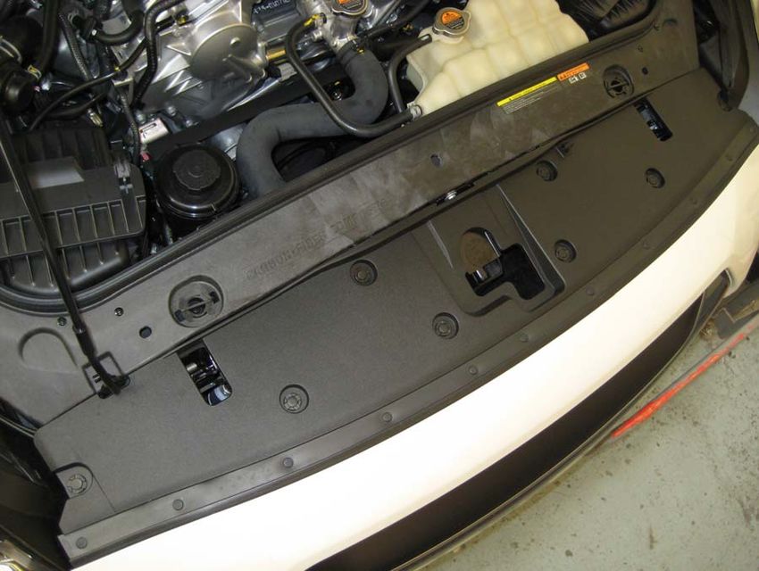
2. Remove the 8 push in clips between the slam panel and the bumper and remove the trim from the car.
3. Pop the side repeaters out of the ends of the bumper by inserting a screwdriver behind them and levering
out until the metal tab is released, then twist the bulb holder to remove the repeater.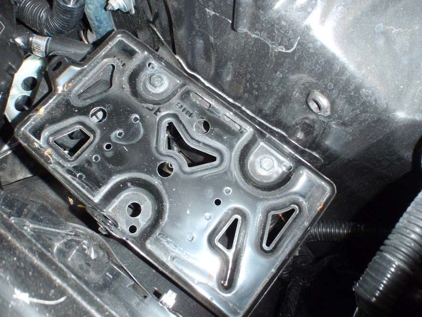
4. Remove the 4 push in clips holding the bottom edge of the arch liner to the bumper, then pull back the edge
    of the liner from the bumper and undo the single 10mm bolt

5. With the arch liner pulled out of the way, you will be able to easier access the other bolt holding the bumper
   to the wing. We found it easiest to use a long extension on a 3/8” drive to get onto the bolt.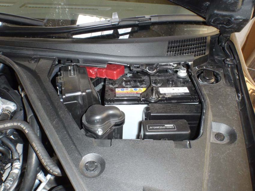
6. Remove the rubber bungs along the front edge of the bumper (10), and the attached undertray (4 at the
    front, 3 at the rear). You’ll notice under the rubber that there is a small slot to enable you to use a small
    screwdriver to prise them out.

7. Remove the 10mm bolt under each bung. You’ll notice that the three bolts at the front of the attached
    undertray are 12mm, leave these until last. Support the weight of the undertray and remove the 12mm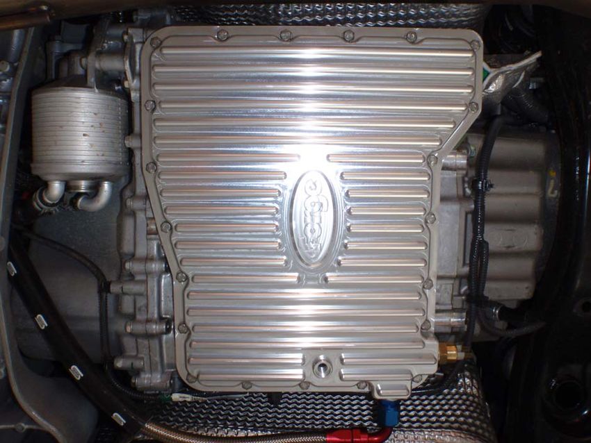
bolts then pull the undertray forwards to release it from the locating lugs at the back and remove it from
    the car.

8. Back in the engine bay, remove the 6 clips holding the front edge of the bumper to the slam panel, by prising
    out the centre of the clip with a small screwdriver. Don’t touch the wiring yet.

                 Bumper wiring
                 connector

9. Release the edges of the bumper from the clips under the headlights, this can be hard, the most important
    thing is if you think you’re using too much force then the clips themselves can be removed if necessary. See
    next step.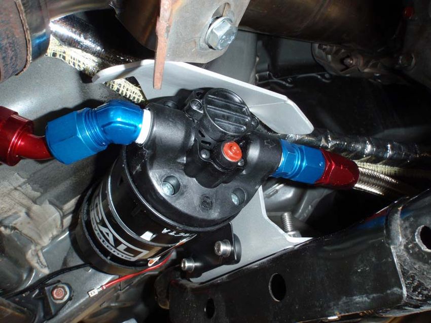
Clips holding the bumper on can be removed if the bumper won’t pull off the clips, by removing the two
   10mm bolts as shown below.

10. If your car is NOT fitted with headlight washers then please skip this step. Pull the washer out of the bumper
     using your fingers, then unclip the cover.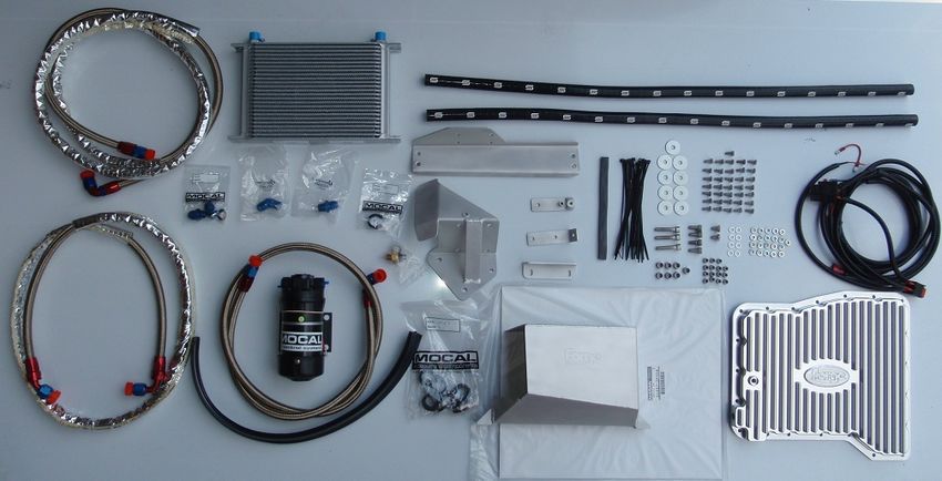
Pull the bumper forward and undo the 10mm bolt holding the back of the washer in place

Push the sprung edge of the washer over to release it from the front face of the bumper, then push the
washer through the hole.
11. Ensure that the ignition is OFF, then separate the plug on the wiring harness to the crash sensors in the front
     bumper (again, if fitted), which can be found on the left side of the slam panel (see picture in step 8)

12. The bumper can now be withdrawn from the vehicle. TAKE CARE to store the bumper horizontally and not
     subject it to any impacts i.e. dropping it, as this may break the crash sensors.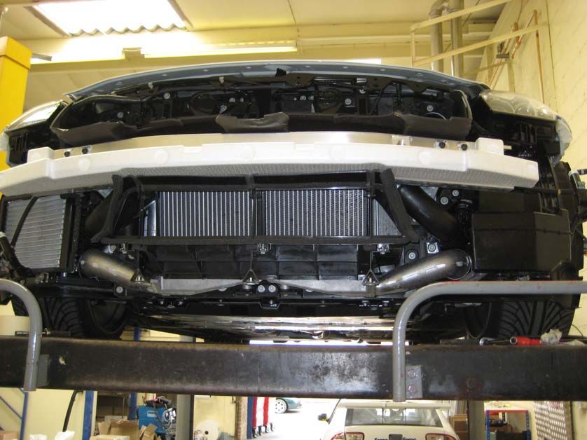
13. Remove the polystyrene piece on the front crash bar, and offer up the oil cooler mount plate to the right
     side of the crash bar (if viewed from the front). Push the plate up so that it’s flush with the underside of the
     crash bar, and the end of the crash bar is in the middle of the notch pre cut into the bracket, then mark the
     four holes on the front face and drill out with a 7mm drill bit. On the underside of the crash bar, mark out
     the one hole nearest the front of the car and drill out with a 5mm drill bit, then tap with an M6 tap.

                                                                    Align end of crash bar
                                                                    with centre of the notch

                               Drill out to 5mm, then
                               tap with an M6 tap
14. Fix the oil cooler to the main bracket off the car, using two M6x12 bolts, plain washers and nyloc nuts on the
right end of the cooler, and an M6x12 countersunk bolt with washer and nyloc on the left rear bolt hole. Fit
a length of the supplied adhesive foam tape as shown below, the height of the cooler.
M6x12 countersunk
M6x12 hex head
Empty
Length of adhesive backed tape
Install the front cowling using two M6x12 bolts, plain washers and nyloc nuts on the lower mounts of the oil
cooler, and bolt on the 90 degree bracket though the cowling again with M6x12 bolts. It should now look
something like this !
M6x12 hex head15. Bolt the oil cooler setup complete to the crash bar, using the appropriate sized bolts as noted below, plain
washers and nyloc nuts. You will struggle to get a nut started on the back of the furthest bolts inside the
crash bar, so we used a ring spanner with one side covered in insulation tape to hold the nut whilst the bolt
is screwed in to it. Tighten all bolts and ensure all the bolts on the cowling are tight too.
M6x12 bolt
M6x16 bolt
M6x12 bolt
screwed up
into crash bar
Cut three lengths of the rubber edging strip provided and fit them to the cowling as shown belowPUMP, SUMP AND OIL LINE INSTALLATION
16. Remove all the remaining undertrays up to the transmission (three in total, one under the engine sump, one
under the downpipes and one under the transmission sump).
17. Remove the four 10mm nuts holding the heat shield above the exhaust where it passes close to the
transmission, and remove the shield.
18. Remove the transmission filler plug next to the prop shaft with a 7mm allen key to allow air to enter the
transmission casing during draining.19. Remove the transmission drain plug in the sump with a 5mm allen head socket and the drain plug insert
behind that, again 5mm allen head. Drain the oil into a suitable container.
20. Remove the 21 bolts around the edge of the sump, starting with each corner, then one bolt to the left of the
corner and so on in a spiral pattern. When you get to the last two bolts, support the sump as there will be
about ¾ litre of oil still in it (you can’t ever completely empty the stock transmission through the drain.) If
you have the chance, it’s a good idea to leave the car draining overnight so as to drain the oil from the
internal walls of the transmission which will make it easier to install the new sump gasket, and less messy.
21. Look carefully at the magnets in the removed sump and study them for any bits of swarf or chunks of metal.
Anything other than a light grey metallic coating is unusual and should be addressed BEFORE this
installation. Remove the magnets with a strong pull, and clean them thoroughly.
This grey coating is normal
22. Use the supplied M8x10 bolts and penny washers, together with some thread lock, to mount the magnets in
the new Forge aluminium sump.23. Clean the sump mating surface on the gearbox so that its free from oil and remnants of the old gasket, and
using the new sump gasket supplied, install the sump with 21 M6x16 bolts and spring washers supplied.
Install all the bolts finger tight initially, then tighten in the following sequence to 7 ft/lb (8.5 Nm)
21 10 9 8 7
1
16 2
15 3
17
14
6 18
19
5
20
4 11 12 13
24. Find the M14 bonded seal, and the M16 bonded seal and push them down over the temperature sensor and
M14x1.5 to ‐8 adaptor respectively. Screw them into the ports on the sump and tighten with a 22mm
spanner.25. Separate out the three custom braided hoses, and locate the one with a long swept 90 deg fitting one end,
and a 45 degree fitting the other (the shorter of the two hoses with a 45 degree fitting). This will be the
pump feed line. Position the 45 degree fitting in the space by the downpipes, then thread the hose down
the transmission tunnel, above the rear beam supporting the gearbox, and loosely screw the 90 deg fitting
into the side of the sump. Don’t worry about it touching other pipes at this point.
26. Find the Mocal oil pump, and with the mounting bracket vertical on the right hand side, normally the Mocal
pumps are supplied with the flow arrow pointing UP (as shown below). This needs to be rotated so that the
flow arrow points to the RIGHT. Follow the instructions below to rotate the housing.
Flow direction arrow
Undo the four screws indicated
and remove the top cowlUndo the two screws indicated
and rotate the top housing 90
degrees to the right. The top
housing doesn’t separate from
the main pump body
Reinstall the screws
Flow direction arrow
Ensure the flow direction arrow now
points to the RIGHT with the mounting
bracket vertical on the RIGHT27. Use the four rubber mounts included with the pump and push them through the pump bracket, but cut
them off flush with the face of the bracket as shown.
28. Mount the pump to the Forge bracket supplied, using the M6x20 allen head bolts, nyloc nuts and plain
washers both sides of the bolt. See picture for orientation.
Pump inlet/outlet under this cowl
29. Find the 3/8NPTF to ‐8 JIC straight adaptor and the 3/8NPFT to ‐8JIC 45 degree adaptor. Use PTFE sealing
tape on the 3/8NPTF ends before screwing them into the pump itself. Observe the orientation shown below
for the 45 degree fitting, which goes on the inlet, the straight fitting on the outlet. Don’t overtighten the
fittings as they are tapered and will seal without being too tight.30. On the rear edge of the front subframe, on the passenger side (for RHD) locate the section shown below,
under the downpipe. Two of the holes go straight through the subframe, the third is blind and needs to be
drilled out with an 8.5mm drill (8 or 9mm will do, just so you have enough clearance for an M8 bolt). Use a
centre punch and drill the hole out. The material is quite soft.
Open holes
Blind hole
31. Use the M8x60 bolts supplied together with penny washers on both sides and nyloc nuts to secure the pump
to the front subframe as shown, tighten the bolts securely.
Find the longest oil cooler hose (with 45
deg fitting one end, and a sharp 90 deg
fitting on the other). This is the oil return
pipe. Pass the 45 degree fitting over the
front anti‐roll bar and under the
driveshaft, then over the top of the oil
cooler pump and along the transmission
tunnel so its within 5mm of the filler on
the front of the gearbox. DON’T attach to
the filler yet.
32.Remove the 10mm nuts that hold the coolant pipes to the transmission tunnel (front and rear) Use the provided straight bracket on the front fitting (it screws on using the M6 threaded boss welded on to the bracket). Orientate the bracket so that it is vertical with the mounting holes below the attachment point, which may mean that its still loose, which is fine. Use two of the 19mm p‐clips and M6x16 bolts with plain washers to LOOSELY secure the p‐clips to the brackets to support the two hoses (feed and return) now running down the transmission tunnel On the rear fixing near the gearbox, use the angled bracket and mount it with the 10mm nut you removed earlier. Use two 19mm p‐clips again, as above LOOSELY fitted.
33. The third and final hose is the feed from the pump to the oil cooler. Take the straight fitting and follow the
     path of the last hose towards the back of the car (i.e. over the anti‐roll bar and under the driveshaft) but
     this time run it between the power steering rack and the subframe. There is a small channel that it fits
     through beside the steering rack (photo taken looking forwards).

     If you struggle to get the fitting through, you can loosen the bolts and nuts securing the steering rack to the
     subframe, and lever the rack slightly whilst you push the pipe through.
34. Loosely screw the 45 degree fitting from step 24 onto the pump . Also screw on the straight fitting from the
     pipe going to the front of the car you just installed.
Use another 19mm p‐clip with M6x16 bolt to secure the return line to the top of the pump bracket (there is
a rivnut to accept the bolt).
35. If all has gone to plan you should have two short swept 90 deg bends on the oil lines at the front of the car.
Bend them loosely to the shape below, around the edge of the front subframe, then between the back of
the rad pack and in front of the arch liner. Screw them both into the bottom of the oil cooler loosely. All oil
cooler lines (apart from the return to the gearbox) should now be loosely fitted where they have got to go.To secure the return to gearbox pipe
under the driveshaft (NOT the one
that goes under the steering rack),
undo this 10mm bolt securing pipes
to the subframe, then reuse the bolt
through the 16mm p‐clip provided.
36.
37. Use the silicon hose provided to prevent the braided oil hoses from rubbing against other pipes and anything
that can be worn away. Cut the silicon hose into lengths then split it along its length with a sharp knife. Slip
the silicon hose over the cooler pipes then secure them together with cable ties.
Front under oil coolerAround the rad pack and end
of the front subframe
The pipes can be secured to
the end of the front subframe
to avoid the lower radiator
hose – pass the cable tie
between the two holes in the
end of the subframe to secure.
Where pipes go under the
driveshaftSecure both pipes together close to
the p‐clip installed in step 36 to
prevent movement of the hoses near
the driveshaft.
You can use more of the silicon
hose over the pump feed pipe
near the gearbox where the pipe
touches the gearbox support and
could come into contact with the
coolant pipes.
Check and tighten all the hose ends, and ensure that none of the braided hoses are rubbing on any rubber or
electrical wiring in the car. Ensure that the hoses cannot touch the front driveshaft – if they can then secure with
cable ties. Refit the sump level insert, but leave the drain plug off the vehicle for the moment.ELECTRICAL WIRING
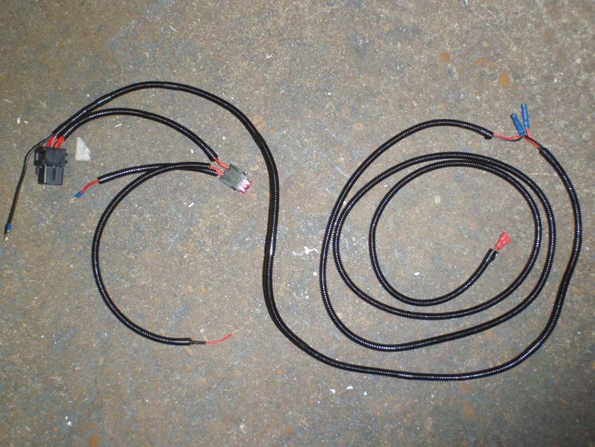
38. Below is the wiring loom laid out which you will install in the car.
Pump connectors
Relay
Temperature sensor connectors
+ve Fuse block
connection
Earth
Signal wire from fuse box
39. This assumes the vehicle is right hand drive. Working in the engine bay, remove the battery cover, and pull
out all the clips that retain the main cover over the wing and remainder of the battery. Pull the cover out
then fold it over onto the engine so that you don’t have to remove the rubber edging.40. Remove the windscreen washer tube from under the remaining plastic panel, then unclip the panel from the
wing and the centre of the car, and pull it out from under the windscreen to remove it from the car.
Remove the two 10mm nuts holding the clamps on to the battery, then remove the negative terminal, and
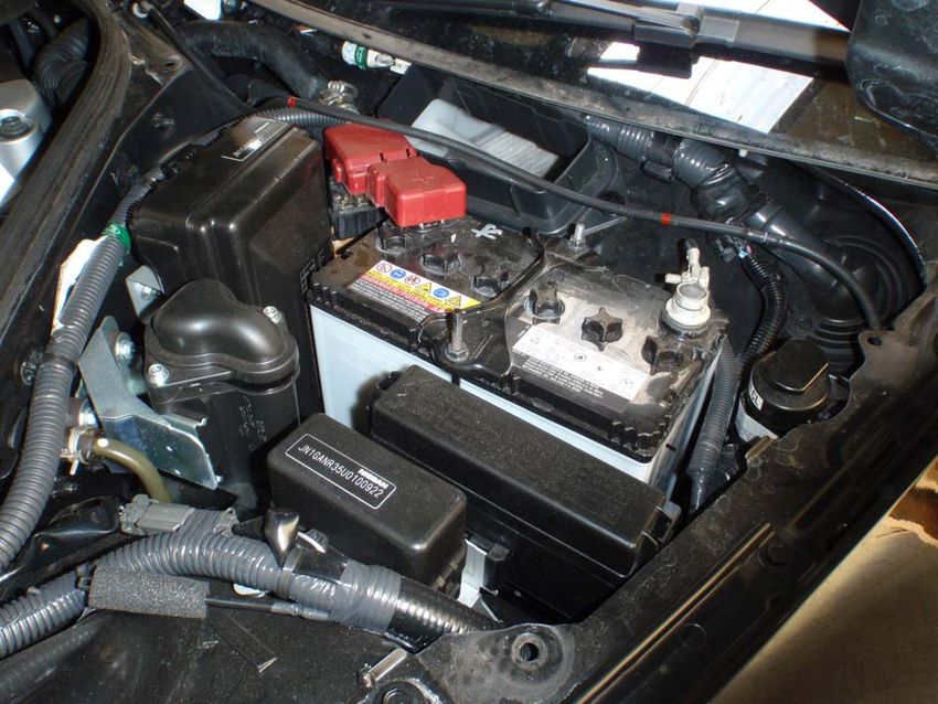
positive terminal wiring from the battery and remove the battery from the car.With the battery removed, remove the plastic battery tray, and then underneath that, remove the two
12mm bolts securing the battery holder from the top (it will still be fixed in place underneath)
41. Working in the passenger side wheel arch (RHD car), remove the rear arch liner and locate the 12mm nut as
shown below. Remove the nut and the battery holder should be free to be removed from within the engine
bay. (It may be easier to remove the road wheel for access, though we just used a jack and put the wheel on
full lock.)Unravel the wiring harness, and locate the end with two spade connectors for the temperature sensor which are on the end of the loom. Push the end of the harness through the hole shown opposite, under the battery holder. The end of the harness will appear in the inner Pull the wiring harness through so a couple of metres are under the car. Start by pressing down both tabs on the back of the fusebox and pull it upwards to release it from the bracket
Undo this 10mm mounting bolt for the
fusebox bracket, and attach the earth
cable from the harness before doing it
back up

Cable tie the relay to the stock wiring
loom, and pass the transmission
cooler loom back behind the fusebox
bracket so that the fuses end up
between the fusebox and the battery

Remove the red plastic cover
over the positive terminal of the
battery, undo the 10mm nut
nearest the front of the car and
attach the red +ve wire from the
loom before reassembling
Position the fuses here so that
 when the covers are reassembled
 you will have access to the fuses
 through the battery inspection
 cover

 Find the bare ended red wire from
 the loom that needs to be connected
 into the fusebox, and route it
 alongside the stock loom into the
 fusebox with a cable tie, tucking it
 into the clip on the bottom of the
 fusebox.

Remount the fusebox and remove the
cover. Use a wire stripper to remove 6‐
8mm of sheathing on the yellow wire with
grey stripe located on the bottom left
connector, 5th wire up on the left.
Another view

Wrap the red wire around tightly
around the exposed part of the yellow
wire and solder in place. After the
solder has cooled and you’ve checked
the joint is good, cover with insulation
tape. Make sure the loom is tight so
that the fusebox cover can fit back on.

Pull the wiring harness down until
the connections for the pump are in
the right position. Strip the ends of
the pump wires back, and crimp the
provided male bullet connector to
the red (+VE) wire on the pump and
the female bullet to the black (‐VE)
wire on the pump as shown. The
connectors may be loosely fitted on
the harness already to save them
from getting lost.
Connect the pump up. The remainder
                                                                      of the loom needs to be pushed
                                                                      through the heat shielding provided –
                                                                      we supply 2 metres, but only 1 to 1.5
                                                                      metres is needed to get the wiring
                                                                      loom to the other end of the
                                                                      transmission tunnel. Secure the loom
                                                                      to the chassis brace bar with one of
                                                                      the provided cable ties.

                                                                   Run the wiring loom along with the
                                                                   feed from the sump and connect it to
                                                                   the temperature switch you installed
                                                                   earlier (it doesn’t matter which way
                                                                   the connectors go). Secure with cable
                                                                   ties.

The battery can now be reconnected and all the panels in the engine bay replaced that were removed in
steps 39‐41
FILLING AND BLEEDING PROCEDURE
42. IF YOU IGNORED EVERYTHING ELSE YOU MUST AT LEAST FOLLOW THESE INSTRUCTIONS VERY CAREFULLY.
If all has gone to plan, all the hoses should now be tight, the electrics all hooked up, and all wiring and
pipework secured. The return to the gearbox will still be disconnected, and the gearbox filler removed from
the car. The sump level should have been inserted, but the sump plug should still be off. Ensure that the
return to the gearbox will not foul on the propshaft whilst its loose !!
Fill the gearbox with appropriate oil until it drips from the sump plug. This should be approx 10 litres of oil.
Temporarily refit the gearbox filler plug, and sump plug, and start the car.
‐Press and hold the brake pedal, then shift the shift lever to ‘N’, then the ‘M’ range 1st gear (wait for 5
seconds), ‘M’ range 2nd gear (wait for 5 seconds), ‘M’ range 1st gear, shift to ‘N’ and stop the engine.
‐ Remove the filler plug and drain plug, then fill the gearbox again until it leaks from the drain hole, and refit
both plugs.
‐ Run the engine again until the transmission oil reaches 50 deg C (122 deg F) on the data monitor
‐ Press and hold the brake pedal, then shift the shift lever to ‘N’, then the ‘M’ range 1st gear (wait for 5
seconds), ‘M’ range 2nd gear (wait for 5 seconds), ‘M’ range 1st gear, shift to ‘N’ and stop the engine.
‐ WAIT FOR 5 MINUTES
‐ Remove the drain and filler plug, and top the transmission oil up until it drips at the rate of 1 drip per
second.
‐Refit both plugs and restart the engine
‐Wait for the transmission oil temp to exceed 75 deg C (167 deg F) ‐ this will take approx 10 minutes.
‐With the engine still running, get an assistant to hold the return line into a jug and using a short length of
wire with two spade connectors on the end, remove the connectors on the temperature sensor and
connect them to the wire. This will override the temperature sensor and fire up the pump to bleed the
system. The system should bleed through in less than 10 seconds, and will pump out very quickly so be
prepared. You want to pump out about 0.5 litres to flush the lines and prime everything. Stop the engine,
and discard this oil.
‐ Remove the drain plug once more and top up the transmission oil again until the drips subside, then
tighten the sump plug for a final time.
‐Use the remaining M18x1.5 to ‐8 JIC adaptor and M18 sealing washer, and screw this into the filler plug
hole on the gearbox. Attach the return line and tighten, ensuring that the hose is out of the way of the
roatating prop shaft. The 45 degree bend on the hose should allow you position it correctly.
‐ Run the engine again, and making sure that the oil is still above 75 deg C, bridge the contacts on the
temperature sensor. This time, keep the pump running and visually inspect all of the joins on the pipework
for leaks. There should be none of course ! Tighten as necessary. When you are happy, remove the bridging
wire, and reconnect the connectors to the temperature sensor.
‐ You can now reinstall the heatshield that you removed in step 17 and all of the undertrays.
‐ In the future when you need to change the oil, there is no need to remove the sump like you did when it
was stock. Simply remove the temperature sensor from the rear of the sump and allow all the oil to drain,
before cleaning and refitting it. Once the gearbox is full of oil, follow the steps above again, but at the point
you bleed the cooler system, allow 2 litres of oil to be pumped through to completely change the oil in the
cooler and lines.BUMPER MODIFICATION
43. The spare duct in the front bumper has to be cut away in order to force feed air through the cooler core.
There are many different ways to achieve this and some customers prefer the maximum amount removed,
some the minimum. It’s probably best for us to leave this to you to cut out as you see fit. The scoop on the
bumper will fit inside the rubber edges of the scoop on the oil cooler. How you shape it to fit is up to you.
Start by cutting out the back of the
scoop (the flat part) to give you a
‘window’ to see through and get as
close as you can to the cooler. This is
easy with a sharp blade On this
example below we then cut a chunk
out for the core. This was then
further enhanced by cutting along
the line shown which gave a much
more open inlet for the air.Shown during test fitting – the
rubber edging will sit above the
duct when fitted properly and
will be invisible. You should have
some left over adhesive backed
foam that you can run down the
edge of the oil cooler where it
runs against the bumper if
necessary
44. A section of the stock splitter/bumper undertray has to be cut out because of the depth of the new oil
cooler. The splitter is double skinned so this will not reduce its strength. Only a small section of the top skin
needs to be removed. With all the undertrays back on the car, you can slot the splitter back on the car and
see how far away the three 12mm bolts that secure the splitter up through the intercooler are away from
fitting, and cut as appropriate. This section shown below was purposely too big, and it can be much smaller
than this.
45. When you are happy with the fit on the bumper, refit the bumper and front splitter/undertray following
steps 12‐1 in reverse order.
Your car can now be lowered to the ground and driven as normal. During hard use, the transmission cooler
will turn on at approx 100 deg C (212 deg F) and turn off again at 95 deg C (203 deg F). Different rating
switches are available from Forge Motorsport for a small cost, though we have found this to be an idealbalance – it allows the transmission oil to get warm enough to boil off any water based contaminants, yet
not get too hot where heat soak in the components means its difficult to bring the temperature back down.
The cooler will ONLY operate with the engine running – if the engine is off but you leave the ignition on,
even with the oil over 100 degrees, the cooler will not run so as to preserve the life of your battery.
ENGINEERED FOR PERFORMANCEYou can also read