CURRENT SENSORS REFERENCE DESIGN GUIDE - Application Note - Melexis
←
→
Page content transcription
If your browser does not render page correctly, please read the page content below
CURRENT SENSORS
 REFERENCE DESIGN GUIDE
 Application Note

This document describes several reference designs for current sensing applications with either
conventional or planar IMC-Hall® sensors. The design solutions cover various current ranges (from 2
to 2000A) and conductor types (bus bar, PCB, cable). Also included is a quick selection guide for
Melexis Hall effect current sensors, general magnetic design guidelines and information on
ferromagnetic materials.
CURRENT SENSORS
REFERENCE DESIGN GUIDE

TABLE OF CONTENTS
CURRENT SENSOR TYPES.......................................................................................................................... 4
 O CONVENTIONAL HALL SENSORS ........................................................................................................... 4
 O PLANAR IMC-HALL® SENSORS ............................................................................................................ 4
1 CONVENTIONAL HALL SENSORS........................................................................................................ 5
 1.1 QUICK SELECTION GUIDE ................................................................................................................ 6
 Examples............................................................................................................................ 7
 1.2 QUICK SELECTION GUIDE ................................................................................................................ 8
 Main features (typical)....................................................................................................... 8
 Option code and sensitivity ................................................................................................ 9
 1.3 ERROR BUDGET CALCULATION .......................................................................................................... 9
2 PLANAR IMC-HALL® SENSORS ......................................................................................................... 11
 2.1 IMC VERSIONS............................................................................................................................ 12
 2.2 MAGNETIC DESIGN ...................................................................................................................... 13
 Magnetic field estimation with shield .............................................................................. 13
 Magnetic field estimation without shield......................................................................... 14
 Dimensioning examples ................................................................................................... 15
 Conductor with neck-down .............................................................................................. 16
 Use of laminated shields .................................................................................................. 16
 Cancelling stray field without shield ................................................................................ 17
 Avoiding cross-talk without shield ................................................................................... 17
 2.3 QUICK SELECTION GUIDE .............................................................................................................. 18
 Main features (typical)..................................................................................................... 18
 Option code and sensitivity range .................................................................................... 19
 2.4 ERROR BUDGET CALCULATION ........................................................................................................ 19
 2.5 PCB DESIGN: GUIDELINE .............................................................................................................. 20
 2.6 REFERENCE DESIGNS .................................................................................................................... 22
 PCB application, 2-10A range, multi-layer/multi-turn solution ........................................ 23
 PCB application, 2-10A range, ferromagnetic shield solution .......................................... 24
 PCB application, 10-50A range ........................................................................................ 25
 Bus bar application, 50-250A range ................................................................................ 26
 Bus bar application, 300-700A range .............................................................................. 27
 Bus bar application, dual range 5A/200A ........................................................................ 28
 Cable application, 10-100A range.................................................................................... 29
3 FERROMAGNETIC MATERIALS......................................................................................................... 30
 3.1 SUPPLIERS .................................................................................................................................. 30
 3.2 FERROMAGNETIC SHIELDS ............................................................................................................. 30
 U-Shield ........................................................................................................................... 30
 Mechanical assembly....................................................................................................... 31
 3.3 FERROMAGNETIC CORES ............................................................................................................... 32
 3.4 FERROMAGNETIC MATERIALS COMPARISON ...................................................................................... 32
4 END-OF-LINE CALIBRATION............................................................................................................. 33
 4.1 INTRODUCTION ........................................................................................................................... 33
 4.2 DIRECT SENSOR CALIBRATION ........................................................................................................ 33
 4.3 MICRO-CONTROLLER LEVEL CALIBRATION ......................................................................................... 33
ADDITIONAL INFORMATION................................................................................................................... 34

REV013 Page 2 of 35 May-21
CURRENT SENSORS
REFERENCE DESIGN GUIDE

CONTACT US .......................................................................................................................................... 34
DISCLAIMER ........................................................................................................................................... 35

REV013 Page 3 of 35 May-21
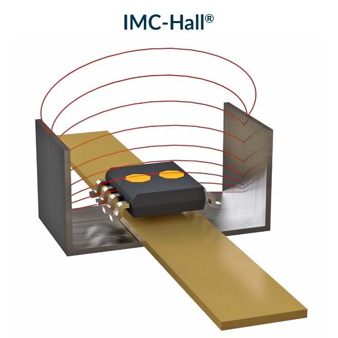
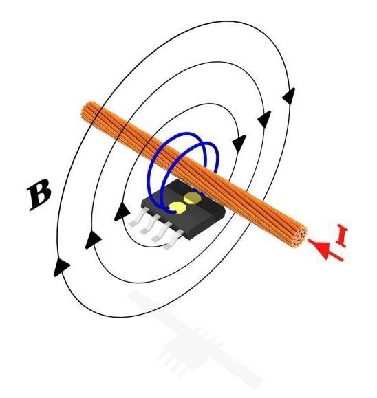
CURRENT SENSORS
REFERENCE DESIGN GUIDE

Current sensor types
Melexis provides two types of current sensors suitable for a broad range of applications.

 o Conventional Hall sensors
These current sensors are sensitive to the magnetic field perpendicular to the chip surface. They are
meant to be used in combination with a ferromagnetic core. In a typical application, the core is
wrapped around the current-carrying conductor and concentrates the magnetic flux on a small air gap
(typically 2-5mm) where the sensor is inserted.

 Pros
 ▪ Strong magnetic gain from the core
 ▪ Very robust against cross-talk
 ▪ Suitable for medium to very high currents

 Cons
 ▪ Performance limited by the core (geometry
 and material): saturation, hysteresis,
 frequency response and thermal drift
 ▪ Bigger footprint (size, weight) than solutions
 based on IMC-Hall® sensors

 o Planar IMC-Hall® sensors
Thanks to the patented integrated magnetic concentrator (IMC) technology, IMC-Hall® sensors are
sensitive to magnetic fields parallel to the chip surface. Thus, the sensors can directly measure the
current flowing in a bus bar or a PCB trace below the package, without the need for a core.

 Pros
 ▪ Sensitive to magnetic field parallel to the chip
 surface, for easy integration and low footprint
 ▪ IMC is made of amorphous magnetic material
 featuring very high permeability and very low
 hysteresis
 ▪ Magnetic gain from IMC

 Cons
 ▪ Requires magnetic shielding or specific design
 to avoid cross-talk and/or noise from external
 fields

REV013 Page 4 of 35 May-21
CURRENT SENSORS
REFERENCE DESIGN GUIDE

 1 Conventional Hall Sensors

REV013 Page 5 of 35 May-21
CURRENT SENSORS
REFERENCE DESIGN GUIDE

1.1 Quick Selection Guide
Conventional hall sensors are typically enclosed in the air gap of a ferromagnetic core (ring or square),
wrapped around the current-carrying conductor.

 d

 I
 d

 I

The magnetic field B at the sensor position (in the center of the air gap), for a current I and a
ferromagnetic core with air gap d, can be approximated as:

 [ ]
 B [mT] = 1.25 ×
 [ ]
Equation 1: Magnetic field estimation formula for core configuration.
The naming convention for ferromagnetic cores is C followed by the air gap dimension (for instance,
C5 for a 5mm air gap shield).

REV013 Page 6 of 35 May-21
CURRENT SENSORS REFERENCE DESIGN GUIDE Examples MLX91207 DVK core A 1.68 I = 100A B = 1.25 x 100 [A] / 1.68 [mm] = 74.4 [mT] required sensor sensitivity: S = 2000 [mV] / 74.4 [mT] = 26.9 [mV/mT] 3.5 MLX91207 DVK core B I = 200A B = 1.25 x 200 [A] / 3.5 [mm] = 71.4 [mT] required sensor sensitivity: S = 2000 [mV] / 71.4 [mT] = 28 [mV/mT] C-5 5 I = 500A B = 1.25 x 500 [A] / 5 [mm] = 125 [mT] required sensor sensitivity: S = 2000 [mV] / 125 [mT] = 16 [mV/mT] REV013 Page 7 of 35 May-21
CURRENT SENSORS
REFERENCE DESIGN GUIDE

1.2 Quick Selection Guide
Melexis provides a list of sensors that can be selected for different applications. Each sensor can be
bought with a factory trimmed sensitivity, using a specific option code. Sensitivity can be tuned
according to customer needs.

 Main features (typical)

 91207 91209 91217 91219
 Sensitivity [mV/mT] * 5-45 5-150 5-150 7-150
 Thermal sensitivity drift [%S] ** ±1.5 ±1.5 ±1 ±1
 Thermal offset drift [mV] ±20 ±10 ±5 ±5
 Non-linearity [%F.S.] ±0.1 ±0.4 ±0.4 ±0.3
 Response time [µs] 8 2 2 2
 Bandwidth [kHz] 60 250 250 400
 Noise [mVrms] 10 10 10 3
 Analog output Yes Yes Yes Yes
 PWM output Yes No No No
 Programmable Yes Yes Yes Yes
 Diagnostic functions
 ▪ Over/Under-voltage detection Yes Yes Yes No
 ▪ Broken-track detection Yes No Yes No
 ▪ Clamping Yes No Yes No
 ▪ Over Current Detection No No No Yes
 Possible supply voltages [V] 5 5 5 5, 3.3
 SOIC-
 Package SOIC-8 VA (SIP) SIP4-VA
 8/SIP4-VA
 Operating temperature range [°C] -40-150 -40-150 -40-150 -40-150
Table 1: Main features and specifications of conventional Hall effect current sensors, at operating
temperature T = -40°C to 125°C, unless otherwise specified.
* Programmable.
** Thermal sensitivity drift is better for temperatures lower than 100°C.

REV013 Page 8 of 35 May-21
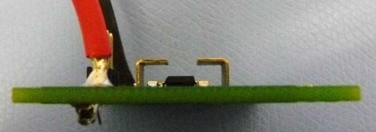
CURRENT SENSORS
REFERENCE DESIGN GUIDE

 Option code and sensitivity

 Sensor Option code Sensitivity range (typical) [mV/mT]
 CAA-005 15-45 (25)
 MLX91207 CAA-007 5-20 (10)
 CAA-015 15-45 (25)
 CAA-000 5-150 (50)
 CAA-001 5-150 (15)
 MLX91209
 CAA-002 5-150 (7.3)
 CAA-003 5-150 (19)
 ACA-000 5-150 (10)
 ACA-001 5-150 (15)
 MLX91217 ACA-002 5-150 (17)
 ACA-003 5-150 (9)
 ACA-005 5-150 (13)
 AAA-500 7-105 (7)
 MLX91219
 AAA-501 7-105 (10)
Table 2: Option code and sensitivity range of conventional Hall effect current sensors. Please contact
the Melexis sales department to have customized versions. Different leads bending options are also
available.

 (a) (b) (c) (d)

Figure 1: Different leads bending options: (a) straight leads, (b, c) bent leads, (d) and planar leads.

1.3 Error budget calculation
Error budget consists in the total 6σ error expected on the output signal (calculates as %FS). To be
evaluated, it is necessary to divide errors in 2 categories: sensitivity errors ( ) and offset errors ( ).
They are calculated as the square root of the sum of squares of all contributions on respectively
sensitivity and offset (Equation 2).

REV013 Page 9 of 35 May-21
CURRENT SENSORS
REFERENCE DESIGN GUIDE

 , = �� , 2

Equation 2: Formula for sensitivity and offset error calculation.

The error budget is then calculated by multiplying the applied current times the sensitivity error and
then summing the offset error, as in Equation 3.

 = × +
Equation 3: Formula for calculation of total error.

An example of budget error plot (Figure 2) and data (Table 3) are shown for device MLX91217.

 Error MLX91217

 Sensitivity accuracy limit 0.1%
 ( 1 )

 Thermal sensitivity drift 1%
 ( 2 )

 Sensitivity drift over lifetime 1%
 ( 3 )

 Non-linearity error ( 4 ) 0.4%

 Assembly tolerances ( 5 ) 0%

 Sensitivity error ( ) 1.47%

 Offset accuracy limit ( 1 ) 0.05%

 Noise ( 2 ) 0.11%

 Thermal offset drift ( 3 ) 0.25%

 Offset drift over lifetime 0.5%
 ( 4 )

 Offset error ( ) 0.57%

 Table 3: Error contributions and values for Figure 2: Budget error plot for sensor
 sensitivity and offset errors for sensor MLX91217 MLX91217, and different cores configurations.

REV013 Page 10 of 35 May-21
CURRENT SENSORS
REFERENCE DESIGN GUIDE

 2 Planar IMC-Hall® Sensors

REV013 Page 11 of 35 May-21
CURRENT SENSORS
REFERENCE DESIGN GUIDE

2.1 IMC versions
 IMC-Hall® sensors are available in 4 different versions/sizes covering a broad range of sensitivities
 and magnetic field ranges: Low Field (LF), High Field (HF), Very High Field (VHF), Extra High Field
 (XHF). With its strong magnetic gain, the biggest IMC (LF) is ideally suited for applications with low
 currents, requiring high magnetic sensitivities (up to 700mV/mT). At the other end of the scale, the
 smallest IMC (XHF) can linearly sense strong magnetic fields up to ±90mT, for current sensing
 applications with very high-power densities.

 Figure 3: Sensitivity range of each IMC version.

Figure 4: Linearity range for different IMC configurations.

REV013 Page 12 of 35 May-21
CURRENT SENSORS
REFERENCE DESIGN GUIDE

 Shield Current [A]
width [mm] 100 200 300 400 500 600 700 800 900 1000 1100 1200 1300 1400 1500 1600 1700 1800 1900 2000 3000 4000
 25 LF HF VHF XHF OCR SAT
 20 LF HF VHF XHF OCR SAT
 15 LF HF VHF XHF OCR SAT
 12 LF HF VHF XHF OCR SAT
 Legend:
 LF - Low field
 HF - High field
 VHF - Very HF
 XHF - Extra HF
 OCR - Over-current range
 SAT - IMC® Saturation

Table 4: Optimal IMC configuration for different current ranges. Saturation of shields should also be
considered. Contact our technical support team to optimize the choice of shields.

2.2 Magnetic design
 Magnetic field estimation with shield

In a typical application, a U-shaped ferromagnetic shield is wrapped around the current conductor to
protect the sensor from external fields and improve the overall robustness of the sensing solution.

Figure 5: Shield dimensions on sensor.

The most important dimension of the shield is the inner width. In this configuration, the magnetic field
B measured by the sensor for a current I and an inner width W can be estimated as:

 [ ]
 B [mT] = 1.25 ×
 [ ]
Equation 4: Magnetic field estimation formula for shield configuration.
The current in the conductor generates a magnetic field around it. The ferromagnetic shield will guide
the magnetic field lines such that a homogeneous magnetic field is generated in the U-shield between
the two legs of the shield, as it is shown in Figure 6.

REV013 Page 13 of 35 May-21
CURRENT SENSORS
REFERENCE DESIGN GUIDE

 Melexis Sensor

 Current Conductor
 Shield

Figure 6: Magnetic field lines distribution in a typical application
Based on these considerations, the following magnetic design rules are essential in order to ensure
optimal performances:
 1. The current sensing module should respect the Ferromagnetic Shield, Current Conductor, and
 Melexis Sensor order of components.
 2. In order to have an increased signal-to-noise ratio, the sensor should be mounted at a certain
 depth inside the opening of the shield, where the field lines are quasi-parallel to each other,
 and therefore homogeneous. A rule of thumb is that the distance from the sensor to the upper
 side of the shield (H’) should be higher or equal to half the width of the shield (W).

 ′ ≥
 2
Equation 5: Optimal distance of sensor to the top of the shield.

Typically, the shield thickness ranges between 0.8 and 1.5mm (proportional to current range). The
height and depth are between 12 and 15mm, in order to properly surround the sensor in each
direction. The naming convention of ferromagnetic shields is U (for standard shields) or LU (for
laminated shields) followed by the width number (for instance, L20). NiFe and SiFe are two available
materials. Different properties are described in section 3.4.

 Magnetic field estimation without shield

Depending on application environment and requirements, the ferromagnetic shield is not necessarily
required. However, this configuration would lead to a drastic reduction of stray field immunity.

REV013 Page 14 of 35 May-21
CURRENT SENSORS
REFERENCE DESIGN GUIDE

Figure 7: dimensions on sensor without shield.

Without shield, the magnetic field B measured by the sensor for a current I, a trace width W and a
vertical position H can be approximated as:

 [ ]
 B [mT] = 1.25 ×
 2 × ( + 2 ) [ ]
Equation 6: Magnetic field estimation formula for a configuration without shield.

 Dimensioning examples

Table 5 provides suggested system dimensions for various current ranges, based on a typical design
with a sensor on top of a straight bus bar surrounded by a U-shaped ferromagnetic shield. These
dimensions can be easily scaled up or down for higher or lower currents according to the magnetic
field estimation formula provided above, even if a solution with narrow shields is preferable.

 Shield geometry Sensor
 Current Magnetic Field
 [A] (peak) Width Thickness [mT] (peak) Sensitivity
 Version
 [mm] [mm] [mV/mT]

 190 12 0.8 20 HF 100
 500 12 1.5 50 VHF 40
 700 15 3 60 VHF 30
 1000 15 3 90 XHF 20
 1200 20 3 75 XHF 25

Table 5: Example of configurations for different current peaks. Other combinations are possible,
please contact Melexis sales department in case interested.

REV013 Page 15 of 35 May-21
CURRENT SENSORS
REFERENCE DESIGN GUIDE

Figure 8: Example of 3-phase inverter current sensing solution with IMC-Hall® sensors.

 Conductor with neck-down

In order to limit the cost, size and weight of the shield on systems with wide bus bars, we recommend
reducing its cross-section locally, as illustrated in Figure 9. Such a neck-down has minimal impact on
the electrical resistance and allows for a much more compact current sensing solution.

 ≈12

 ≈18 ≈10

Figure 9: Necked-down bus bar example.

 Use of laminated shields

Laminated shields are made of a stack of thin sheets separated by insulators. This allows to reduce the
effect of eddy currents (that are generated in the shield by time oscillating fields, and cause gain
reduction and phase shift of the sensor signal), boosting the sensing performances. Moreover, for
very high currents (typically above 800A), it is often more efficient and cost-effective to use a
laminated shield so that the in-plane thickness can be increased, decreasing the depth and overall
footprint for the same performance.

Figure 10: Shield configuration for very high currents.

REV013 Page 16 of 35 May-21
CURRENT SENSORS
REFERENCE DESIGN GUIDE

 Cancelling stray field without shield

In AC applications, external stray fields can be cancelled out by the microcontroller. Computing the
difference between max and min sensor output values provides a signal independent of any parasitic
DC field.

Figure 11: Stray field cancelling without shield.

 Avoiding cross-talk without shield

Even without ferromagnetic shield, cross-talk between adjacent current tracks can be avoided by
design. Figure 12 illustrates a concept of current trace layout with slots to force the current to flow
perpendicular to the main track axis. The sensors are rotated by 90° with their sensitive axis (blue
arrow) parallel to the current trace. With such a configuration, there is virtually no cross-talk between
phases.

Figure 12: Current trace layout with slots and rotated sensors to avoid cross-talk between phases.

REV013 Page 17 of 35 May-21
CURRENT SENSORS
REFERENCE DESIGN GUIDE

2.3 Quick Selection Guide
Melexis provides a list of sensors that can be selected for different applications. Each sensor can be
bought with a factory trimmed sensitivity, using a specific option code. Sensitivity can be tuned
according to customer needs.

 Main features (typical)

 91208 91216 91218***
 Sensitivity [mV/mT] *
 ▪ Extra High Field version (XHF) 20-125 18-125
 ▪ Very High Field version (VHF) 30-200 30-200 30-200
 ▪ High Field version (HF) 50-300 50-350
 ▪ Low Field version (LF) 100-700
 Thermal sensitivity drift [%S] ** ±1.5 ±1 ±1
 Thermal offset drift [mV] ±10 ±5 ±5
 Non-linearity [%F.S.] ±0.5 ±0.3 ±0.3
 Response time [µs] 2 2 2
 Bandwidth [kHz] 250 250 400
 Noise [mVrms] 10 6.5 5
 Analog output Yes Yes Yes
 PWM output No No No
 Programmable Yes Yes Yes
 Diagnostic functions
 ▪ Over/Under-voltage detection Yes Yes No
 ▪ Broken-track detection No Yes No
 ▪ Clamping No Yes No
 ▪ Over Current Detection No No Yes
 Possible supply voltages [V] 5 5 5, 3.3
 Package SOIC-8 SOIC-8 SOIC-8
 Temp. range [°C] -40-150 -40-150 -40-150
Table 6: Main features and specifications of planar IMC-Hall® current sensors. Operating temperature
T = -40°C to 125°C, unless otherwise specified.
* Programmable
** Thermal sensitivity drift is better for temperatures lower than 100°C.
*** Target specifications.

REV013 Page 18 of 35 May-21
CURRENT SENSORS
REFERENCE DESIGN GUIDE

 Option code and sensitivity range

 Sensor Option code IMC version Sensitivity range (typical) [mV/mT]
 CAL-000 LF 100-700 (250)
 CAH-000 HF 50-300 (100)
 MLX91208
 CAV-000 VHF 30-200 (40)
 CAV-001 VHF 30-200 (60)
 ACH-000 HF 50-350 (100)
 ACV-000 VHF 30-200 (40)
 ACV-001 VHF 30-200 (60)
 MLX91216 ACV-002 VHF 30-200 (30)
 ACX-000 XHF 20-125 (25)
 ACX-001 XHF 20-125 (30)
 ACX-002 XHF 20-125 (20)
 ARV-5XX VHF 30-200
 ARV-500 VHF 30-200 (40)
 ARV-501 VHF 30-200 (60)
 ARV-502 VHF 30-200 (30)
 MLX91218
 ARX-5XX XHF 18-125
 ARV-303* VHF 18-125 (30)
 ARX-300* XHF 12-80 (14)

Table 7: Option code and sensitivity range of planar IMC-Hall® current sensors (supply voltage equal
to 5V unless otherwise specified). Please contact the Melexis sales department to have customized
versions.
* Supply voltage 3.3V

2.4 Error budget calculation
Error budget calculation for IMC-Hall® sensors is performed with the same method as discussed for
conventional Hall sensors in section 1.3. An example of error budget analysis for sensor MLX91216 is
shown in Table 8 and Figure 13.

REV013 Page 19 of 35 May-21
CURRENT SENSORS
REFERENCE DESIGN GUIDE

 Error MLX91216

 Sensitivity accuracy limit 0.1%
 ( 1 )

 Thermal sensitivity drift 1%
 ( 2 )

 Sensitivity drift over lifetime 1%
 ( 3 )

 Non-linearity error ( 4 ) 0.5%

 Assembly tolerances ( 5 ) 0%

 Sensitivity error ( ) 1.5%

 Offset accuracy limit ( 1 ) 0.05%

 Hysteresis ( 2 ) 0.24%

 Noise ( 3 ) 0.16%

 Thermal offset drift ( 4 ) 0.4%

 Offset drift over lifetime 0.5%
 ( 5 )

 Offset error ( ) 0.57%

 Table 8: Error contributions and values for Figure 13: Budget error plot for sensor MLX91216,
 sensitivity and offset errors for sensor and different shields configurations.
 MLX91216.

2.5 PCB Design: Guideline
The PCB design and layout play an important role in the final performances of the current sensing
module. More specifically, two different aspects are to be considered when designing the ground layer
on the PCB.
When an application implies high voltage switching (for instance in motor control applications), an
expanded ground layer, as depicted in Figure 14, will help reducing the parasitic coupling capacitance
generated by voltage time transients (dV/dt).

REV013 Page 20 of 35 May-21
CURRENT SENSORS
REFERENCE DESIGN GUIDE

Figure 14: Current sensing structure. Expanded Ground Layer on PCB in order to reduce the parasitic
coupling capacitance (coming from voltage transients).

At the same time, the ground layer can have a big impact on the response time.
If the ground layer covers all the surface of the PCB and surrounds the two legs of the shield, Eddy
currents will start to flow circularly around them, generating a counter-magnetic field which slows
down the response time of the sensor.
In order to avoid increased response time, the ground layer should be divided such that it interrupts
the circulations of Eddy currents around the shield.

Figure 15: Current Sensing Structure – Designing the Ground Layer on the PCB such that Eddy Currents
circulations is interrupted

REV013 Page 21 of 35 May-21
CURRENT SENSORS
REFERENCE DESIGN GUIDE

2.6 Reference Designs
Table 9 shows an overview of reference designs based on planar IMC-Hall® current sensors.

 Application Solution Illustration
 Multi-turn and multi-layer PCB
 PCB trace current
 Single layer PCB with C-shaped
 2-10A
 ferromagnetic shield

 PCB trace current
 Single layer PCB with or without
 ferromagnetic shield
 10-50A

 Bus bar
 High field sensor with 12mm U-
 shaped ferromagnetic shield
 50-250A

 Bus bar
 Very high field sensor with 12mm
 U-shaped ferromagnetic shield
 300-700A

 High dynamic range
 Dual range sensor with U-shaped
 and C-shaped shields
 50mA to 250A

 Non-intrusive current
 sensing from cable Simple PCB with clamp-on shield
 wrapped around the cable
 10-100A

Table 9: Overview of the reference designs based on planar IMC-Hall® current sensors.

REV013 Page 22 of 35 May-21
CURRENT SENSORS
REFERENCE DESIGN GUIDE

 PCB application, 2-10A range, multi-layer/multi-turn solution

▪ PCB with multiple layers and trace windings (current loops) for very high sensitivity.
▪ Can be used with or without ferromagnetic shield, depending on sensitivity and accuracy
 requirements.

Figure 16: PCB layout example for very high sensitivity with 6 windings on 3 layers.

 3 windings 3 windings 6 windings 6 windings
 w/o shield w/ shield w/o shield w/ shield
 Sensitivity (max) [mV/A] 210 350 420 700

Table 10: Maximum achievable sensitivities with Melexis evaluation boards.

 550mV/A

 330mV/A

Figure 17: Example of output functions for a six-winding evaluation board, with/without shield.

REV013 Page 23 of 35 May-21
CURRENT SENSORS
REFERENCE DESIGN GUIDE

 PCB application, 2-10A range, ferromagnetic shield solution

▪ PCB with one layer and a single current trace (no windings).
▪ Closed ferromagnetic shield for high magnetic gain.

 Assembly Concepts

 Figure 18: Shield in one piece inserted through slots on the PCB edge.

 Figure 19: Shield in two parts inserted in PCB slits and assembled together.

 167mV/A

Figure 20: Example of output function for a single-layer PCB with closed shield.

REV013 Page 24 of 35 May-21
CURRENT SENSORS
REFERENCE DESIGN GUIDE

 PCB application, 10-50A range

▪ PCB with one layer and a single current trace.
▪ To be used with or without ferromagnetic shield (U-shaped).
▪ Sensitivity: up to 60mV/A (without shield) and 170mV/A (with shield).

Figure 21: Single-layer evaluation board without and with shield.

Figure 22: Shield assembly through PCB slits.

 65mV/A

 40mV/A

Figure 23: Example of output function for a single-layer PCB, with/without shield.

REV013 Page 25 of 35 May-21
CURRENT SENSORS
REFERENCE DESIGN GUIDE

 Bus bar application, 50-250A range

▪ The high field (HF) sensor on PCB is mounted directly above the conductor.
▪ A simple, low-cost and compact U-shaped shield is mounted around the sensor to protect it from
 stray fields and ensure good signal robustness against vibrations and displacements.
▪ With the dimensions demonstrated here, the linearity error is lower than ± 1.5A up to ±250A.

Figure 24: Demonstrator based on MLX91206 HF sensor and U12 shield with 0.8mm thickness.

Figure 25: Shield dimensions.

 20mV/A

Figure 26: Typical output and non-linearity of a sensor calibrated for ±100A.

REV013 Page 26 of 35 May-21
CURRENT SENSORS
REFERENCE DESIGN GUIDE

 Bus bar application, 300-700A range

▪ With the very high field (VHF) sensor, the measurement range can be extended to 700A while
 keeping the same inner width than for the previous design (12mm). Only the shield thickness must
 be adapted from 0.8 to 1.5mm.
▪ The linearity error is lower than ±5A up to ±650A.
▪ Very compact solution to measure 700A with a footprint of less than 2cm2.

 12
 1.5

Figure 27: Demonstrator based on MLX91208 VHF sensor and U12 shield with 1.5mm thickness.

Figure 28: Sensor output and linearity error versus current.

REV013 Page 27 of 35 May-21
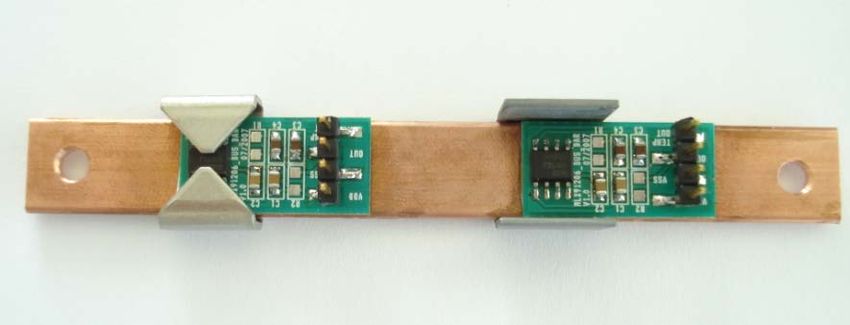
CURRENT SENSORS
REFERENCE DESIGN GUIDE

 Bus bar application, dual range 5A/200A

▪ Solution for applications with a wide dynamic range.
▪ One sensor with C-shaped (closed) shield for high accuracy at small currents (typ. ±5A).
▪ One sensor with U-shaped shield for high saturation limit (typ. ±200A).
▪ Other combinations of ranges are possible depending on the application requirements.

 ±5A range ±200A range

 View Dimension [mm]

 thickness = 0.8mm

 S=400mV/A S=10mV/A
 20-25mA accuracy 200mA accuracy

Figure 29: Typical output of the 5A and 200A range sensors.

REV013 Page 28 of 35 May-21
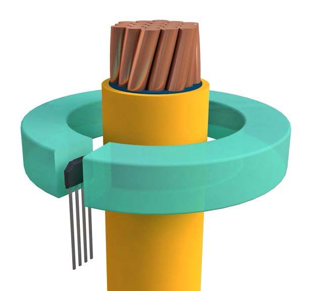
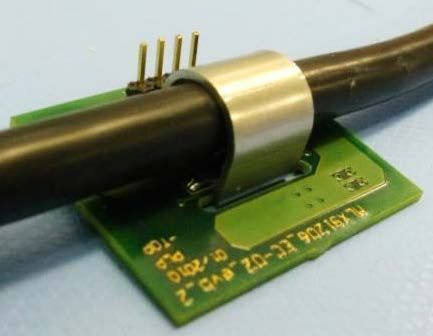
CURRENT SENSORS
REFERENCE DESIGN GUIDE

 Cable application, 10-100A range

▪ The clamp-on shield gathers the magnetic field around the cable and concentrates it above the
 sensor package. Small air gap ensures high magnetic gain.
▪ Shield geometry can be adapted to match various cable diameters and current ranges.

Figure 30: Cable clamp concepts (left: monolithic shield, right: two-part shield in plastic housing).

Figure 31: Implementation examples (monolithic and two-part shield in plastic housing).

 50mV/A

Figure 32: Example of output function with a cable-clamp demonstrator calibrated for ±40A.

REV013 Page 29 of 35 May-21
CURRENT SENSORS
REFERENCE DESIGN GUIDE

3 Ferromagnetic materials
3.1 Suppliers
Melexis partnered with MagLab and PML India for ferromagnetic material supply.

 www.maglab.ch www.pmlindia.com

Recently, PML and MagLab signed an exclusive collaboration in the field of contactless current sensing.
This cooperation between MagLab and PML offers an efficient and cost-effective solution for
customers requiring magnetic shields. MagLab takes care of the engineering side, while PML
manufactures the products to our specifications.

3.2 Ferromagnetic shields
 U-Shield

Standard (U) and laminated (LU) shields can be ordered using the following order codes convention
(valid for both types).

 U-Shield – Width – Length – Height – Thickness (– Ni)

 Order code example W [mm] L [mm] H [mm] T [mm]
 U-Shield – 12 – 13 – 12.5 – 0.8 12 13 12.5 0.8

 Material Specification T [mm] Ni [%]
 Standard material 0.8 48
 Other Thickness options 0.35 / 0.5 / 1 / 1.2 …

Figure 33: Ordering information for the standard U-shield from MagLab.

REV013 Page 30 of 35 May-21
CURRENT SENSORS
REFERENCE DESIGN GUIDE

 Mechanical assembly

Ferromagnetic shields can be assembled by crimping, screwing or bonding (glue or tape). They can
also be encapsulated in a pre-molded plastic case. The optimal solution depends on the application.
In any case, care should be taken to avoid mechanical stress on the part of the shield involved in the
magnetic measuring circuit.

Figure 34: Several solutions for shield assembly.

One of the most common solutions is to use a pre-molded plastic case, with slots to insert the shields,
as illustrated on the pictures below.

Figure 35: Assembly with pre-molded plastic case.

REV013 Page 31 of 35 May-21
CURRENT SENSORS
REFERENCE DESIGN GUIDE

3.3 Ferromagnetic cores
Amorphous ferromagnetic cores can be ordered with the following order codes convention.

 AMC1R5 – L
 Order code example L [mm]
 AMC1R5 – 5 5

Laminated cores can be ordered using the following order codes convention.

 Ca – b – c

 Order code example a [mm] b [mm] c [mm]
 C2.5 – 4 – 3.8 2.5 4 3.8

3.4 Ferromagnetic materials comparison
The performance of the current sensing solution relies on the careful selection of a proper core or
shield material and manufacturing conditions (annealing, lamination, etc.).
Table 11 displays the main features of the most common material types.

 Saturation field Hysteresis
 Material Price
 density BSAT[T] [%FS]
 SiFe $$ 1.5
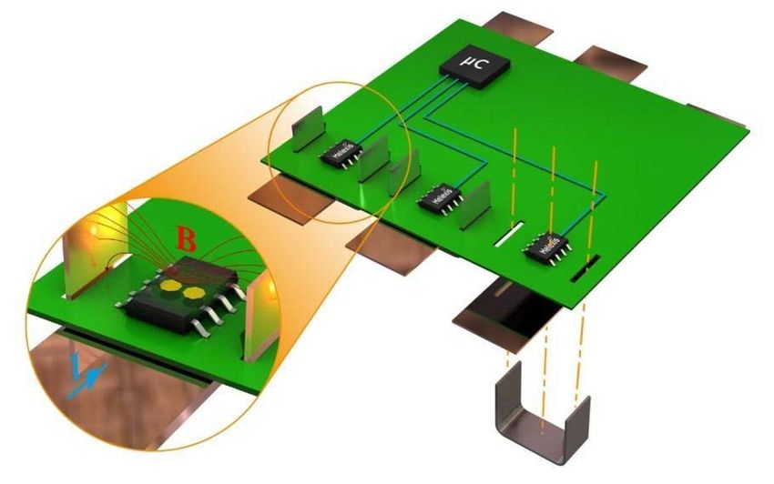
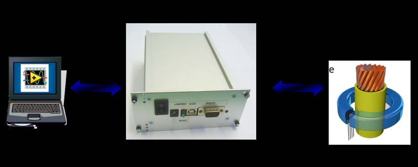
CURRENT SENSORS
REFERENCE DESIGN GUIDE

4 End-of-line Calibration
4.1 Introduction
Each current sensor is individually tested and calibrated over temperature on the Melexis production
line. However, in order to achieve optimal accuracy, a final calibration is required at customer-side
after assembly to compensate for mechanical tolerances (sensor position deviations, shield
dimensions, etc.)
This final calibration can be done in two ways: either by using the Melexis tools to directly program
the sensor EEPROM, or by adjusting the gain/offset at microcontroller level.

4.2 Direct sensor calibration
All current sensor products (starting from MLX91206) can be programmed using the Melexis universal
programmer (PTC-04) and related software. The PTC-04 communicates with the sensor through 3- or
4-wire connectors, and with the PC through USB or RS-232. Melexis provides a library of sensor-
specific high-level functions (.dll), which can be used to develop custom software using common
programming language (C/C++, Labview, etc.)
The calibration is a fast two-step process: the sensor output function (gain and offset) is adjusted
automatically based on two reference measurements (i.e. zero current and nominal current).

Figure 36: scheme of PTC-04 connection.

4.3 Micro-controller level calibration
A micro-controller level correction is recommended for multi-sensors applications, i.e. on power
distribution units, where typically 12 to 24 sensors are on the same PCB in order to monitor the current
of each channel.
All of these Melexis current sensors are factory calibrated over temperature. After assembling of the
factory-calibrated sensors on each channel, a reference current is applied on each channel. The output
voltage of each sensor is measured and the required corrective factor is thus calculated and stored in
the microcontroller.

REV013 Page 33 of 35 May-21
CURRENT SENSORS
REFERENCE DESIGN GUIDE

Additional Information

Please refer to the following document for additional information on specific topics:

Typical cores and shield geometries
Standard designs of laminated and un-laminated U-shields and C-cores.

Current sensors programming and calibration
Different options available for customers in terms of sensor calibration.

Magnetic linearity and hysteresis
Application note focusing on the magnetic performance of Hall sensors and ferromagnetic materials.

Contact us

To get in contact with our current sensors application team, please fill and submit the technical inquiry
form.

REV013 Page 34 of 35 May-21
CURRENT SENSORS
REFERENCE DESIGN GUIDE

Disclaimer
The content of this document is believed to be correct and accurate. However, the content of this document is furnished "as
is" for informational use only and no representation, nor warranty is provided by Melexis about its accuracy, nor about the
results of its implementation. Melexis assumes no responsibility or liability for any errors or inaccuracies that may appear in
this document. Customer will follow the practices contained in this document under its sole responsibility. This documentation
is in fact provided without warranty, term, or condition of any kind, either implied or expressed, including but not limited to
warranties of merchantability, satisfactory quality, non-infringement, and fitness for purpose. Melexis, its employees and
agents and its affiliates' and their employees and agents will not be responsible for any loss, however arising, from the use
of, or reliance on this document. Notwithstanding the foregoing, contractual obligations expressly undertaken in writing by
Melexis prevail over this disclaimer.

This document is subject to change without notice, and should not be construed as a commitment by Melexis. Therefore,
before placing orders or prior to designing the product into a system, users or any third party should obtain the latest version
of the relevant information.
Users or any third party must determine the suitability of the product described in this document for its application, including
the level of reliability required and determine whether it is fit for a particular purpose.

This document as well as the product here described may be subject to export control regulations. Be aware that export might
require a prior authorization from competent authorities. The product is not designed, authorized or warranted to be suitable
in applications requiring extended temperature range and/or unusual environmental requirements. High reliability
applications, such as medical life-support or life-sustaining equipment or avionics application are specifically excluded by
Melexis. The product may not be used for the following applications subject to export control regulations: the development,
production, processing, operation, maintenance, storage, recognition or proliferation of:
1. chemical, biological or nuclear weapons, or for the development, production, maintenance or storage of missiles for such
weapons;
2. civil firearms, including spare parts or ammunition for such arms;
3. defense related products, or other material for military use or for law enforcement;
4. any applications that, alone or in combination with other goods, substances or organisms could cause serious harm to
persons or goods and that can be used as a means of violence in an armed conflict or any similar violent situation.

No license nor any other right or interest is granted to any of Melexis' or third party's intellectual property rights.

If this document is marked “restricted” or with similar words, or if in any case the content of this document is to be reasonably
understood as being confidential, the recipient of this document shall not communicate, nor disclose to any third party, any
part of the document without Melexis’ express written consent. The recipient shall take all necessary measures to apply and
preserve the confidential character of the document. In particular, the recipient shall (i) hold document in confidence with at
least the same degree of care by which it maintains the confidentiality of its own proprietary and confidential information,
but no less than reasonable care; (ii) restrict the disclosure of the document solely to its employees for the purpose for which
this document was received, on a strictly need to know basis and providing that such persons to whom the document is
disclosed are bound by confidentiality terms substantially similar to those in this disclaimer; (iii) use the document only in
connection with the purpose for which this document was received, and reproduce document only to the extent necessary for
such purposes; (iv) not use the document for commercial purposes or to the detriment of Melexis or its customers. The
confidentiality obligations set forth in this disclaimer will have indefinite duration and in any case they will be effective for no
less than 10 years from the receipt of this document.

This disclaimer will be governed by and construed in accordance with Belgian law and any disputes relating to this disclaimer
will be subject to the exclusive jurisdiction of the courts of Brussels, Belgium.

The invalidity or ineffectiveness of any of the provisions of this disclaimer does not affect the validity or effectiveness of the
other provisions.
The previous versions of this document are repealed.

Melexis © - No part of this document may be reproduced without the prior written consent of Melexis. (2021)

IATF 16949 and ISO 14001 Certified

REV013 Page 35 of 35 May-21
You can also read