Fuel Performance Requirements - Mitch Meyer Director, Characterization and Advanced PIE Idaho National Laboratory - Oregon State University
←
→
Page content transcription
If your browser does not render page correctly, please read the page content below
Fuel Performance Requirements

 Mitch Meyer
www.inl.gov

 Director, Characterization and Advanced PIE
 Idaho National Laboratory

 September 2017
Introduction
• From the ‘I’ states
• Ph.D. in Material Science & Engineering from Iowa State
 University (1995)
• Argonne National Laboratory 1996-2004, Idaho National
 Laboratory 2004-present
• Experience: Research reactor fuel, fast reactor
 transmutation fuel, light water reactor transmutation fuel,
 gas fast reactor fuel, breed and burn fuel, advanced LWR
 fuels, accident tolerant fuels
• Currently Director of Advanced Characterization and PIE

 2
Outline
• Nuclear fuel
• General design requirements
• Design considerations/constraints
• Example: Low enrichment research reactor fuel
 – Phase 1: Fuel Candidate Selection
 – Phase 2: Concept Definition and Feasibility
 – Phase 3: Design Improvement and Evaluation
 – Phase 4: Fuel Qualification and Demonstration
• Example: Gas-cooled fast reactor fuel
 – Phase 1: Fuel Candidate Selection

 3
Development & Safety Testing
 Four phases of fuel development process
w of 4 phases of fuel
opment process
 1. Fuel candidate
 Fuel candidate
 selection selection
 Concept definition
 2. Concept and and
 definition
 feasibility
 feasibility
 Design improvement and
 3. Design improvement
 evaluation
 and evaluation
 Fuel qualification and
 4. Fuel qualification and
 demonstration
 demonstration
ral needs that drive transient
afety testing

 4
rom: Crawford, et al., Journal of Nuclear Materials, 371 (2007) 232-242.
Nuclear Fuel
• Fuel is the ‘heart’ (coeur) of a nuclear reactor
• Fuel facilitates transfer of fission energy to a
 system that converts it to usable power – it is a
 heat source
• Can be solid or liquid (or vapor, conceptually)
• Solid fuel (which we will focus on today) is
 composed of a fuel material and cladding
 material
• The cladding isolates the fuel from the coolant
 (and the coolant from the fuel) and prevents
 release of fission products
• Advances in fuel technology play a critical role
 in development of advanced nuclear energy
 systems

Nuclear Fission

Nuclear Fission:
• Unstable nucleus formed
235U +n® 236U

236U ® F1 + F2 + 2.43 n + E
• E = 200 MeV/fission (190
MeV useful)
• E = 21,600 kWhr/g 235U

 This is both wonderful (for nuclear engineers) and terrible (for material scientists)
Neutron Displacement Damage

 Imagine that you are an atom …..

Simulation of Neutron Displacement Damage

v
Material Degradation

• Hardening/increase in yield strength
• Void swelling
• Radiation induced segregation (RIS)
• Radiation induced precipitation
• Irradiation enhanced creep
• Radiation enhanced diffusion
• Neutron transmutation (ex. Al-> Si)
• He gas generation (larger issue for 14 MeV fusion
 neutrons)
• Anisotropic growth (zirconium alloys)
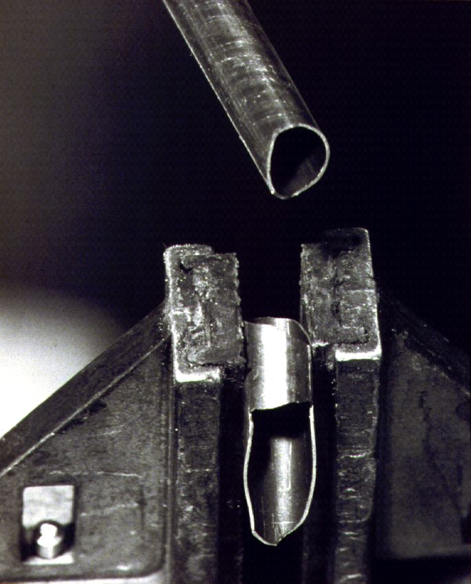
Mechanical Integrity can be Compromised by
Neutron Damage

 • Void induced
 embrittlement
 • 14% swelling
 • 316 stainless steel
 irradiated at ~400ºC
 • Failure occurred during
 clamping in a vise at room
 temperature
 • Embrittlement threshold at
 ~10% swelling

 Porter and Garner, 1988
Nuclear fuel operating conditions
 Cladding: stainless steel or Zircaloy
 Gas pressurization of
 cladding tube
 Fuel
 Fuel
 ~100 MeV heavy fission fragments
 Fission gas bubbles (Xe, Kr) lead to very high defect densities,
 cause fuel swelling very fast diffusion

 Fuel-clad chemical
 interaction as a result
 Neutrons cause
 of fuel and fission
 cladding damage
 products

 s
 Steep temperature gradient can
 Fuel-clad lead to large difference in
 mechanical T chemical potential and drive
 interaction constituent migration
 results from
 fuel swelling Solid fission products
 cause fuel swelling,
 change in composition
 (oxygen potential in
 TRUOx)
 Fuel irradiation testing is extremely important!
Evolution of UO2 chemical composition

 Fission fragments
 • High energy (100 MeV)
 • Short range (7-14
 micrometers)
 • Solid fission product
 volume > volume of
 uranium
 • About 25% of fission
 products are Xe + Kr gas
 • Result is a fuel volume
 increase (swelling)
Example: Irradiation Behavior of Pu-Zr alloys
Waldren, et. al. (1958)
 • d-phase Pu-35Zr, cast/extruded
 • 500°C, 0.83% burnup (all atoms)
 • Swelling = 6.5% per at% burnup
 • r = 10.25 g/cm3, rPu = 6.7 g Pu/cm3

Horak, et. al. (1962)
 • a-Zr phase Zr-5Pu, rolled
 • 530°C, 0.9% burnup (all atoms)
 • Swelling = 3.3% per at% burnup
 • Extreme growth

• Fuel irradiation behavior can be sensitive to composition, crystal
 structure, crystallographic texture, etc.
General Fuel Requirements

• Mechanical Integrity Reactor
• Geometric Stability Operation

• Stable and Predictable Behavior
• Mission Envelope Fabrication
• Test to Verify Performance Fuel
 Performance
• Fabrication Process
Nuclear Fuel Design Considerations/Constraints
• Requirements, operating environment, fabrication processes,
 and cost translate into design constraints
• Irradiation behavior of fuel material
 – Swelling and fission product release consistent with reactor design
 goals
 – Consistent behavior, minimal relocation, large margin to breakaway
 swelling
 – Degradation of properties with irradiation
• Irradiation behavior of cladding material
 – Mechanical properties sufficient to withstand operational loads
 – Ability to retain fuel in a coolable geometry during normal and off-
 normal conditions
 – Fission product retention
 – Degradation of thermal and physical properties during irradiation
 – Robust during fuel handling and long-term storage
Nuclear Fuel Design Considerations/Constraints

• Neutron absorption cross section of fuel and cladding
 – Neutrons lost = increased fuel cost
• Fissile atom density
 – Low density = shorter cycles and increased fuel cost
• Thermal properties/melting temperature
 – Nuclear fuel operates at high power density
 – Combination of heat capacity, thermal conductivity and melting
 temperature sufficient to prevent melting during normal and
 anticipated off normal events
Nuclear Fuel Design Considerations/Constraints
• Compatibility of fuel with cladding
 – Fuel chemical reaction with cladding occurs at an acceptable rate
• Corrosion resistance of cladding
 – Cladding chemical reaction with cooling occurs at an acceptable rate
• Corrosion resistance of fuel
 – Reliability of cladding is not 100%; there will always be cladding
 failures
 – Corrosion resistance of fuel by cooling must not cause unacceptable
 consequences
• Fuel cost/performance tradeoff
 – Fuel with high performance or reliability may justify higher cost
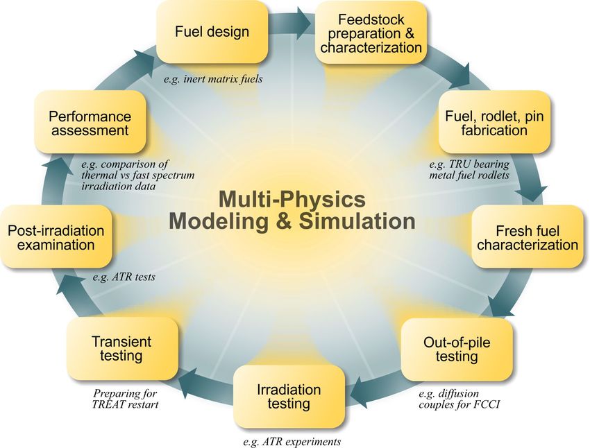
Fuel Development R&D Life Cycle
• Define requirements The Fuel Development R&D Lifecycle
• Select fuel concepts that meet
 requirements
 – Geometry
 – Materials
• Analysis of Performance
 – Fuel Performance
 – System performance
• Fabrication
• Testing
 – Separate effects
 • Ion irradiation
 • Thermal cycling (out-of-pile)
 • Nuclear fuel R&D cycle is 3-6
 • Materials in a neutron years
 environment • Time to deployment > 20 years
 – Integral irradiation testing
 • Simple → complex
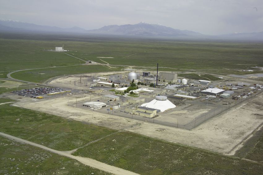
Example 1: Low Enrichment Test Reactor Fuel
• Goal: Eliminate more than 200 kg of HEU from commerce annually by converting five research
 reactors.
• No suitable LEU fuel exists. Must develop and qualify a new, high density, low enriched fuel
• Must establish the capability to fabricate the fuel
• Facilities include:
 • MITR-II reactor at the Massachusetts Institute of Technology (MIT),
 • Missouri University Research Reactor (MURR) at the University of Missouri–Columbia,
 • National Bureau of Standards Reactor (NBSR) at the National Institute of Standards and
 Technology (NIST) in Maryland,
 • Advanced Test Reactor and the associated critical assembly (ATR and ATR-C) both at
 Idaho National Laboratory (INL), and
 • High Flux Isotope Reactor (HFIR) at Oak Ridge National Laboratory (ORNL).
• MITR-II, MURR and NBSR are regulated by the U.S. Nuclear Regulatory Commission, ATR
 and ATR-C are regulated by DOE’s Office of Nuclear Energy (DOE-NE), and HFIR is regulated
 by DOE’s Office of Science (DOE-SC).

 19
Fuel Development Phase 1: Fuel Candidate Selection

• Primary Design Requirements

 – Maintain high thermal neutron flux

 – Maintain cycle length
Primary Design Requirements
• Maintain high thermal neutron flux
 – High flux levels allow accelerated testing
 – High flux => high power density
 – High power density requires efficient removal of heat
 • Not a power producing system (no steam)
 • Tcoolant < 100oC

• Maintain cycle length
 – High power density requires high fissile atom density
 (>1.6 g 235U/cm3 fuel)
 – Use of low-enrichment uranium (235U< 20 %, > 8 g-
 U/cm3 in fuel core)
 – High burnup (fission density ~ 7.8x10²¹ f/cm3; 100%
 LEU burnup)
Fuel Geometry

• Heat rejection from the fuel
 is the dominant design
 requirement
• High surface/volume for
 heat transfer
 – Short heat transfer path
• Must be able to economically
 fabricate the fuel
Fuel Geometry

 • Heat rejection from the fuel
 is the dominant design
 requirement
 • High surface/volume for
 heat transfer
 • Short heat transfer path
 • Must be able to economically
 fabricate the fuel
Fuel Geometry
• Heat rejection
 from the fuel is
 the dominant
 design
 requirement
 • Dispersion fuel
• High – Fuel particles embedded in a matrix
 surface/volume of high conductivity material
 for heat transfer (aluminum)
 • Short heat transfer – Localization of fission damage and
 path fission products
 – Robust fuel performance
• Must be able to – Fuel loading limit of 50%
 economically
 – Uranium density > 16 g-U/cm3 in fuel
 fabricate the fuel phase required at 20% 235U
 enrichment
Materials
 • Aluminum
 – Kt ≈ 130 W/mK
 – Tm = 660oC
• Considerations for – σa = 0.232 barns
 cladding and matrix
 material • Molybdenum
 – Kt ≈ 50 W/mK
 – Thermal conductivity
 – Tm = 2620oC
 – Melting temperature
 – σa = 2.6 barns
 – Corrosion resistance
 – Material compatibility • Zircaloy
 – Irradiation behavior – Kt ≈ 16 W/mK
 – Neutron absorption cross – Tm = 1850oC
 section – σa = 0.184 barns
 – Fabrication
 – Reprocessing
 • Stainless steel
 – Kt ≈ 18 W/mK
 – Tm = 1510oC
 See, for example, IAEA-TECDOC-1496 – σa = 2.7 barns
Fuel Material

• Considerations for
 fuel phase:
 – Uranium density
 – Irradiation behavior
 – Compatibility with
 cladding
 – Thermal conductivity
 – Corrosion resistance
 – Fabrication
 – Reprocessing
Fuel Material

• Considerations for
 fuel
 – Uranium density
 – Irradiation behavior Low Density
 – Compatibility with
 cladding
 – Thermal conductivity
 – Corrosion resistance
 – Fabrication
 – Reprocessing
Fuel Material
 • Considerations for fuel
 • Uranium and U6Fe (U6Mn, U6Ni) – Uranium density
 – Uranium density high – Irradiation behavior
 – Irradiation performance is – Compatibility with cladding
 unacceptable – Thermal conductivity
 – Corrosion resistance
 – Fabrication
 – Reprocessing

 Low Density

 Irradiation Behavior

 Irradiation Behavior

M. Meyer, “Irradiation behavior of U6Mn-Al dispersion fuel elements,” JNM 278 (2000).
Fuel Development Phase 2: Concept Definition and
Feasibility
• Low temperature, high burnup irradiation behavior of U-Mo (and U-Nb-
 Zr) alloys is unknown
• Irradiation testing required to generate data
• U-xMo with x> 6 wt.% perform well to high burnup in scoping tests

 U-5Nb-3Zr at 41% 235 U burnup U-10Mo at 69% 235 U burnup
Fuel/Cladding Compatibility Al (U-Mo)Alx Optical micrograph of failed fuel SAD pattern of amorphous phase Higher temperature irradiation testing (Tfuel~200oC) reveals that fuel reacts with the Al matrix to form a (U- Mo)Alx phase (where x≈7) This phase is unstable under irradiation
IRIS-2 PIE

 • Unstable irradiation behavior leads to
F. Huet, RRFM 2005
 issues with mechanical integrity and
 geometric stability
Materials
• Considerations for fuel
 – Uranium density
 – Irradiation behavior
 – Compatibility with Low Density
 cladding
 – Thermal conductivity
 – Corrosion resistance Irradiation Behavior
 – Fabrication
 – Reprocessing Fuel/Matrix Compatibility
 Irradiation Behavior

 • U-Mo is stable – no indication of
 unacceptable behavior
 • (U-Mo)/Alx is the problem
 • No other fuel material choices
 • Have to fix the problem
 U-10Mo
Potential Solutions
• Alter the chemistry of the fuel
 and/or matrix material
 - Addition of silicon to the
 aluminum matrix stabilizes
 lower aluminides and provides
 significant (but not enough)
 improvement
• Change the matrix material Micrograph of Mg matrix fuel after irradiation to
 - Magnesium and uranium don’t 5.5x10²¹ f/cm3 at ≈ 170oC (Keiser 2012) shows that
 react chemically no fuel/matrix reaction occurs.

 - Fails due to irrational fear U-7Mo/Al-2Si 70% burnup RERTR-4 U-10Mo/Al 80%
 burn-up
• Coat the fuel particles
 - Thin layer required (1 m) to
 meet fuel density
 requirements
 - ZrN provides significant
 improvement, but fails at high Micrographs of U-Mo fuel with 2 wt.% Si in the matrix (left) and
 fission density with no Si in the matrix (right)
Potential Solutions
• Eliminate the aluminum matrix
• Aluminum clad U-Mo ‘monolithic’ fuel

 Aluminum

 U-Mo Fuel

 80% (LEU) burn-up (100% in failure region)
 BOL Heat Flux 260 W/cm2

 • Performance improves
 • Failure mode persists at U-
 Al Mo/Al interface
 U-Mo
Potential Solutions
• Eliminate the aluminum matrix
• Zirconium clad U-Mo ‘monolithic’ fuel

 • Eliminates the U-Mo/Al
 interaction issue
 • Changes the cladding-to-
 coolant interface
 • Concerns about potential
 reactor water chemistry issues
Solution!
• Monolithic U-Mo fuel
• Zirconium diffusion barrier
• Aluminum cladding

 Al
 U-Mo
 Al
U-10 Mo monolithic fuel
• Meets irradiation performance requirements to a fission density > 1x10²²
 f/cm3
• Issues with repeatability of fabrication process

 L1P754 – Mid Plane 8x10²¹ fissions/cc (Robinson 2012)
Fuel Development Phase 3: Design Improvement and Evaluation

Monolithic U-Mo fuel requirements Reactor
• Mechanical Integrity Operation
• Geometric Stability
• Stable and Predictable Behavior
• Mission Envelope Fabrication
• Test to Verify Performance Fuel
 Performance
• Fabrication Development
Specific U-Mo Monolithic Fuel Requirements

Mechanical Integrity Geometric Stability Stable and
• Ensure no • Plate movement caused Predictable Behavior
 delamination during by pressure differential • Fuel performance
 normal operation and does not compromise shall be known and
 anticipated transients ability to cool the fuel predictable
• Mechanical response • Geometry is maintained • Fuel swelling is within
 of the fuel meat, during normal operation a stable regime
 cladding, and and anticipated • U-Mo corrosion
 interlayers is transients behavior after breach
 established • Irradiation–induced is known
 degradation of • Irradiation behavior
 properties does not lead on scale up is
 to conditions that result predictable
 in loss of coolability
Mechanical Integrity
 90000"

 80000"
 Bounding + 15% • Fuel is tested in
 steady state with
Peak%Plate%Volumetric%Power%(W/cc)%

 70000"
 ATR"Plate"19"
 margin beyond
 60000" HFIR"IFE:1"
 the normal
 50000"
 MITR"Plate"1" operating regime
 Bounding MURR"Plate"23" • Testing envelope
 40000"
 NBSR"Plate"17" is determined by
 30000" OperaCng"Envelope"
 conversion
 element design
 Envelope"with"15%"
 20000" Margin"
 U:Mo/Zr"accept"
 10000"
 U:Mo/Zr"fail"

 0"
 0.00E+00" 2.00E+21" 4.00E+21" 6.00E+21" 8.00E+21" 1.00E+22" 1.20E+22"
 Plate%Peak%Fission%Density%(f/cc)%

 No delamination has been found during normal operation and
 anticipated transients
Mechanical Integrity
 90000"
 High power density
 80000" region of design space
 driven by HFIR and ATR
 Peak%Plate%Volumetric%Power%(W/cc)%

 70000"
 ATR"Plate"19"

 60000" HFIR"IFE:1"

 MITR"Plate"1"
 50000"
 MURR"Plate"23"
 40000"
 NBSR"Plate"17"

 30000" OperaCng"Envelope"

 Envelope"with"15%"
 20000" Margin"
 U:Mo/Zr"accept"
 10000"
 U:Mo/Zr"fail"

 0"
 0.00E+00" 2.00E+21" 4.00E+21" 6.00E+21" 8.00E+21" 1.00E+22" 1.20E+22"
 Plate%Peak%Fission%Density%(f/cc)%
ATR stack gas activity monitoring indicated that approximately five discrete releases occurred over
 the last week of operation as shown in Figure 3. It appears that individual blisters of different size may
 have ruptured and released fission gases into the coolant. As the gas pressure inside the blister was
 relieved, the stack gas activity trends back to normal levels after each event. It was also observed that the
 Mechanical Integrity
 primary coolant system activity was largely unaffected by the events as shown in Figure 4 (an upward
 trend in activity is normal during a typical ATR operating cycle).

 • In-reactor overheating
 event with AFIP-6
 irradiation test
 • Peak fuel meat
 temperature ~500°C
 • Peak FD 3.4x10²¹ f/cm3
Figure 13. Cross section through blister at lowest fueled region of the plate (left) and down

 • Behavior consistent
 with out-of-pile heating
 studies
 • Plate blistered, periodic
 (a)

 fission gas release (11
 days)
 showing edge behavior (right).

 • No fuel integrity issues
 Figure 3. ATR stack gas activity measured by the Real Time Monitor during ATR cycle 146B.vii
 (b)

 No delamination during normal operation and anticipated
 transients
Mechanical Integrity
 Mechanical response of the fuel meat, cladding, and interlayers shall
 be established

• Finite element-based
 modeling is the primary Stress
 tool used to understand
 mechanical response
 - Failure analysis
 - Parametric studies that
 Porosity
 define sensitivity to
 specific properties and
 irradiation conditions
• Reliable data on
 properties are important Temperature
Fuel Properties
ion

onal UT
can

 Laser-UT scans

 Bend testing of
 irradiated U-Mo
 fuel meat

 Laser shockwave measurement
 of bond strength

 • Irradiated fuel properties as a function of burnup
 - U-Mo strength and modulus
 13
 - Fuel/cladding and cladding/cladding bond strength
 - Residual stress
 - Thermal properties (objective: thermal conductivity)
 • Unirradiated properties (same)
Specific U-Mo Monolithic Fuel Requirements
Mechanical Integrity Geometric Stability Stable and
• Ensure no • Geometry is maintained Predictable Behavior
 delamination during during normal operation • Fuel performance
 normal operation and and anticipated shall be known and
 anticipated transients transients predictable
• Mechanical response • Irradiation–induced • Fuel swelling is within
 of the fuel meat, degradation of a stable regime
 cladding, and properties does not lead • U-Mo corrosion
 interlayers is to conditions that result behavior after breach
 established in loss of coolability is known
 • Plate movement caused • Irradiation behavior
 by pressure differential on scaleup is
 does not compromise predictable
 ability to cool the fuel
Geometric Stability
• Geometry is maintained during normal operation and anticipated
 transients

• Channel gap probe used to verify channel gap dimensions in fuel
 elements between irradiation cycles
 - Completed: AFIP-7 test assembly
 - ET-1, ET-2, MURR-DDE, MITR-DDE, NBSR-DDE (total of 13 more elements)
Geometric Stability
 3BZ Thickness Measurements AFIP-4 blister
• Geometric stability 1.45 testing
 during normal
 1.4
 operation is also
 demonstrated

 Thickness (mm)
 1.35

 through irradiation 1.3

 and PIE of full-size
 1.4-1.45
 1.35-1.4
 1.3-1.35

 fuel plates
 1.25
 1.25-1.3
 1.2-1.25

• Geometric stability 1.2
 13.97
 35.814
 57.658

 during off-normal 79.502
 101.346
 123.19
 145.034
 166.878
 188.722
 210.566
 232.41
 254.508
 conditions is

 276.352
 298.196
 320.04
 341.884
 363.728
 385.572
 407.416
 429.26
 demonstrated

 451.104
 472.948
 495.046
 516.89
 538.734
 through blister testing !
 (~50% of full-size
 plates, >100 tests)
 AFIP-3BZ postirradiation examination

 • Geometry is maintained during normal operation and
 L1B33Zanticipated
 Figure 20. Photographs of the blister tested AFIP-4 plates,
 (front side), and L1B51Z (back and front side).

 transients Table 8. Information on blisters observed on AFIP-4 plates
 Plate Blister ID Blister Type Local
 (1 or 2) Fission
 Densit
 × 1021
 fiss/cm
 L1B33Z 1 2 4.85
Geometric Stability
• Plate movement caused by pressure differential
 does not compromise ability to cool the fuel

 ‘Pinned’ test
 plate

 ‘Fixed’
 flow plates
 GTRI Hydro-
 Mechanical Flow Test
 Pressure differential Facility at Oregon
 between the large channel State University
 and the small channel
 under flow cause the the
 U-Mo/Al test plate to
 Generic Test Plate Assembly (GTPA)
 deflect
Specific U-Mo Monolithic Fuel Requirements

Mechanical Integrity Geometric Stability Stable and
• Ensure no • Plate movement caused Predictable Behavior
 delamination during by pressure differential • Fuel performance
 normal operation and does not compromise shall be known and
 anticipated transients ability to cool the fuel predictable
• Mechanical response • Geometry is maintained • Fuel swelling is within
 of the fuel meat, during normal operation a stable regime
 cladding, and and anticipated • Irradiation behavior
 interlayers is transients on scale up is
 established • Irradiation–induced predictable
 degradation of • U-Mo corrosion
 properties does not lead behavior after breach
 to conditions that result is known
 in loss of coolability
Stable and Predictable Behavior
 6.2x10²¹ f/cm3
 (79% LEU BU)

 8.4x10²¹ f/cm3
 (107% LEU BU)

 Fission gas bubble lattice is a
 key indicator of stability 9.5x10²¹ f/cm3
 against gas-driven (122% LEU BU)
 breakaway swelling

 Fuel swelling is within a stable regime
Stable and Predictable Behavior
• In reactor cladding
 breaches
• RERTR-7 L1T020
 • Transient liquid !
 phase bonding
• RERTR-10A L1P145
 • Delamination/corrosi
 on induced failure !

 • L1T020 fuel cladding bond-line crack over
 70% of the top of plate and 60% of on edge
 • Fission density ~4x10²¹ f/cm3 (~50% BU)
 • Operation for 16 days following detection of
 fission gas at stack monitor
 • 53% of fuel eroded from plate (~3 g)
 • Total fuel plate swelling ~30%
 U-Mo corrosion behavior after breach is
 !
 known
Stable and Predictable Behavior
• Irradiation testing completed on fuel at 4 cm to 1 m scale
• Both fuel plate and fuel element configurations

 Irradiation behavior is predictable on scale up
Fuel Development Phase 4: Fuel Qualification and Demonstration
• Awaiting demonstration of
 production-scale fabrication
 process
 - Scale up of fabrication process
 for full-size fuel foils and plates
 did not consistently meet
 specifications Warping issues (top) and Zr defect in full-size U-Mo foils
 • Foil warping, stress corrosion Fuel Testing Program
 cracking, foil curvature after
 shearing, areas of blistered or Reactor Conversions

 missing Zr MITR DDE

 • Minimum/maximum fuel zone NBSR DDE

 violations, minimum clad thickness MURR DDE

 violations Fuel Qualification Report to NRC

• Program currently focused on Element
 Test-1
 Element
 Test-2

 fabrication development and Full-size plate-1

 scale up Fuel Fabrication Process Selection

 MP-1 MP-2
 - Qualification testing will resume | | | | | | | | | | |
 in 2018 2017 2018 2019 2020 2021 2022 2023 2024 2025 2026
Example 2: Gen IV Gas-cooled Fast Reactor
 Sustainability
 – Conversion ratio ~ 1.0
 – Actinide recycle
 Economics
 – High-temperature, direct
 cycle
 – High efficiency (~48%)
 – Hydrogen generation
 Proliferation resistance
 – Closed fuel cycle, no
 separation of U, Pu, MA
 Safety and Reliability
 – Dependent on robust fuels
 and materials to withstand
 accident conditions
GFR Reactor Operating Behavior
• GFR core
 – High fuel density, high power density relative to thermal spectrum gas-
 cooled reactors (10X, 100 MW/m3)
 • High decay heat
 – Large coolant volume, lack of moderator
 – Low core heat capacity
• Behavior during unprotected loss of coolant much different than for
 thermal spectrum gas-cooled reactors
 – Adiabatic temperature rise at 7% decay heat
 • GT-MHR - 0.2 K/s (12 K/minute)
 • GFR (100 MW/m3) – 5.2 K/s (312 K/minute)
 – Peak fuel temperatures up to 2000°C during some accident scenarios
• Design goal: no core restructuring
• Accident behavior drives fuel design
GFR Fuel Requirements
• Goal: Fuel that will withstand GFR ‘blowdown’
• Several factors selected for screening fuel

 Requirement Reference Value
 Melting/decomposition >2000°C
 temperature

 Radiation induced ????
 swelling

 Fracture toughness Driven by in-core stress
 and handling reqts.

 Thermal conductivity Driven by fuel temperature
 operation limit and thermal
 stress reqts.
 Neutronic Materials allow low core
 HM density and safety
 parameters
GFR Fuel
• TRISO fuel technology can’t be used
 – Fuel density 5-10X lower than required
 – Poor irradiation behavior of pyrocarbon at high
 dose
• Pin-type fuel
 – No cladding material available that meets
 GFR requirements
 – SiC may be possible, early stage of
 development
 – Nb-1Zr marginally acceptable neutronically,
 embrittlement
• Refractory matrix dispersion fuels
 – Cermets (ceramic fuel in metal matrix)
 – Cercer (ceramic fuel in ceramic matrix)
 – No data pertaining to GFR conditions
Matrix Melting Point Requirements
 H He

 Li Be B C N O F Ne

 Na Mg Al Si P S Cl Ar

 K Ca Sc Ti V Cr Mn Fe Co Ni Cu Zn Ga Ge As Se Br Kr

 Rb Sr Y Zr Nb Mo Tc Ru Rh Pd Ag Cd In Sn Sb Te I Xe

 Cs Ba La Hf Ta W Re Os Ir Pt Au Hg Tl Pb Bi Po At Rn

 Ce Pr Nd Pm Sm Eu Gd Tb Dy Ho Er Tm Yb Lu

 • Elements that meet the requirement for Tm > 2000°C in
 green
 • Several others Tm > 1800°C in light gray
Thermal Conductivity
 450
 Delta T Max. Principal Stress
 400

 350

 300
Delta T, Stress

 250

 200

 150

 100

 50

 0
 0 10 20 30 40 50
 K, W/mK

 • Finite element analysis of composite
 - Core power density of 70 MW/m3
 - Calculation of temperature gradients and thermal stress
 • Requirement: K >> 10 W/m·K to minimize thermal stress
Fracture Toughness
• Ceramic materials exhibit
 low (no) ductility
 – Fracture behavior and
 strength are governed by
 distribution of flaws in the
 material
• KIC – ‘fracture toughness’
 often used to characterize
 resistance to crack
 propagation in material
• Difficult to formally define a
 requirement
• Selected min. value of 12
 MPa·m1/2 based on
 comparison with known
 behavior of other materials
GFR Fuel Matrix Requirements
• Goal: Fuel that will withstand GFR ‘blowdown’

 Requirement Reference Value
 Melting/decomposition 2000°C
 temperature

 Radiation induced 12 MPa m1/2

 Thermal conductivity >>10 W/m·K

 Neutronic Materials allow low core
 HM density and safety
 parameters
UO2 Cermet Dispersion

• Nb, Mo matrices
• 80 vol% UO2 loading
• UO2 85 ~ 90 % theoretical
 density
• BOL temperature 1480°C
• Burnup 4+% initial HM
• 1.4% density decrease on
 irradiation Postirradiation metallography of
 80 vol% UO2 Nb cermet (Keller,
 1963)
Matrix Requirements: Neutronic
H He

Li Be B C N O F Ne

Na Mg Al Si P S Cl Ar

K Ca Sc Ti V Cr Mn Fe Co Ni Cu Zn Ga Ge As Se Br Kr

Rb Sr Y Zr Nb Mo Tc Ru Rh Pd Ag Cd In Sn Sb Te I Xe

Cs Ba La Hf Ta W Re Os Ir Pt Au Hg Tl Pb Bi Po At Rn

 Ce Pr Nd Pm Sm Eu Gd Tb Dy Ho Er Tm Yb Lu

 • Requirement – Core fissile inventory and safety parameters
 • B, Nb, Mo, Ru, Hf, Ta, W, Re, Os, Ir disallowed due to poor
 neutronic performance
 • C is marginal neutronically
Matrix Requirements: Irradiation Behavior
 H He

 Li Be B C N O F Ne

 Na Mg Al Si P S Cl Ar

 K Ca Sc Ti V Cr Mn Fe Co Ni Cu Zn Ga Ge As Se Br Kr

 Rb Sr Y Zr Nb Mo Tc Ru Rh Pd Ag Cd In Sn Sb Te I Xe

 Cs Ba La Hf Ta W Re Os Ir Pt Au Hg Tl Pb Bi Po At Rn

 Ce Pr Nd Pm Sm Eu Gd Tb Dy Ho Er Tm Yb Lu

• Swelling < 2% over fuel lifetime for based on estimates for structural and
 thermal performance
• C disallowed due to high swelling under GFR operating conditions (80 dpa,
 T~ 1000°C)
Ceramic Materials
• Disqualification of metals and
 metalloids
 – Low melting temperature Oxides Carbides Nitrides
 – Poor neutronic properties
 – Inadequate irradiation stability
 Al2O3 SiC AlN
....leads to consideration of
 ceramics CeO2 TiC CeN
 – Oxide
 – Carbides MgAl2O4 VC Si3N4
 – Nitrides
 MgO YC2 TiN
• Partial list of materials
 meeting melting and Y2O3 ZrC YN
 neutronic criteria
 ZrO2 ZrN
• Intermetallics not seriously
 considered
 – No irradiation behavior data
Thermal Conductivity
• Thermal conductivity
 requirement eliminates
 consideration of most Oxides Carbides Nitrides
 oxides and CeN
• MgO is disqualified due to Al2O3 SiC AlN
 high vapor pressure
 CeO2 TiC CeN
• Thermal conductivity of a
 bulk solid is microstructure MgAl2O4 VC Si3N4
 dependent
 – Values for many materials MgO YC2 TiN
 not well known or
 adequately characterized Y2O3 ZrC YN
 – Thermal conductivity
 generally decreases during ZrO2 ZrN
 irradiation
Thermal Conductivity of Irradiated SiC
 • kth = 60-140 W/m·K
 unirradiated
 • 5-15 fold reduction on
 neutron irradiation
 • Postirradiation annealing
 allows partial recovery of
 kth
 • kSiC likely to be in the
 range 10 ~ 22 W m-1 K-1
 Senor et al. (1996) during irradiation
Irradiation Behavior
• Irradiation behavior database is
 sketchy for most materials
 considered Oxides Carbides Nitrides
 – Swelling
 – Thermal conductivity
 degradation
 Al2O3 SiC AlN
 – Mechanical property
 degradation
 – Irradiation creep behavior CeO2 TiC CeN
• More extensive irradiation
 behavior database for SiC MgAl2O4 VC Si3N4
• Materials highlighted in green are MgO YC2 TiN
 candidates
 Y2O3 ZrC YN
Irradiation behavior
 Unknown ZrO2 ZrN
 Known to be unacceptable
 Probably adequate
Irradiation Behavior: UC Dispersion in SiC

 • Potential fuel for AGR
 program in the U.K.
 • Coated (BISO) particles in
 reaction bonded SiC matrix
 • Two irradiations in U.K.
 • 5% HM burnup
 • Power to 39 kW/m
 • 750° - 1200°C
 • No matrix damage
 • Xe, Kr R/B ~ 10-6
 Reference: J.V. Shennan, “Preparation of Nuclear
 Fuels Nuclear Engineering- part XVIII-Dispersed
 Ceramic Fuels for the Advanced Gas-Cooled
 Reactor,” (1967)
Fracture Toughness
• Goal:
 – KIC >12 MPa·m½ Material KIC (MPa ·m½)

• No monolithic ceramic SiC 4-6
 materials meet fracture
 toughness goal TiC --
• Microstructural modification
 ZrC --
 required to reach target
 – Ductile phase reinforcement
 TiN 5
 – Fuel/particle interface materials
• Clad elements to maintain ZrN 4-7
 configuration??
Other Considerations
• Oxidation Resistance
 – SiC is known to perform well to T >1550°C in oxidizing
 environments due to formation of protective SiO2 scale
 – Other candidates are less characterized and do not behave as
 well
• Fabrication
 – Fabrication methods for SiC well developed
 – Other materials present new issues
• Material Properties
 – Good database for SiC, sparse data on other materials
• Nitrogen Enrichment of Nitrides
• Integral Fuel Irradiation Performance Data
• SiC is selected as best candidate matrix material
GFR Dispersion Fuel – U.S. Reference
 Cladding SiC matrix

 • (U,Pu)C fuel - 0.3 – 0.7 mm particles
 • SiC bi-layer particle coating
 • SiC matrix

 72
Fuel Performance Modeling
• Finite element analysis of temperature, stress, swelling, etc. in
 dispersion and pin-type fuels
• Custom code development and adaptation of commercial FEA
 packages
• Macroscopic and microscopic models
Fuel Fabrication

• Atomization used to produce
 ZrC microspheres
 - High yield
 - No liquid waste
 - Some shrinkage pores
• Coating at ORNL
• Matrix consolidation process
 development important
 74
Irradiation Testing of Fuel Concepts
 • Honeycomb structures and caps for
 FUTURIX CONCEPT irradiation : SiC and SiC
 TiN
 • SiC and SiC-SiCf as structural materials
 • Liner materials: sheet of metal or coating
 (W / W-Re / Mo / Mo-Re / …)

 TiN obtained by HIP from SACLAY

 French R&D partnership (N. Chauvin) 75
Gen IV Gas-cooled Fast Reactor
 Sustainability
 – Conversion ratio ~ 1.0
 – Actinide recycle
 Economics
 – High-temperature, direct
 cycle
 – High efficiency (~48%)
 – Hydrogen generation
 Proliferation resistance
 – Closed fuel cycle, no
 separation of U, Pu, MA
 Safety and Reliability
 – Dependent on robust fuels
 and materials to withstand
 accident conditions
The Fuel Development R&D Lifecycle
The Fuel Development R&D Life Cycle

 • Each iteration of this cycle requires 3 – 6 years
 • Development of a new fuel requires 20 (+) years
Nuclear Science User
 Facilities (NSUF)
• Ion irradiation can provide
 screening data
 – Many universities offer this
 service
• ‘Rabbit’ testing provides a
 mechanism for evaluation at low
 neutron dose
• Static capsules allow for higher
 neutron dose under ‘nominal’
 conditions
• Instrumented tests allow
 temperature and load control
• Loop tests provide prototypic light
 water reactor environment
• ATR National Scientific User
 Facility provides cost free access
 – Google ‘NSUF’
Summary
• Opportunities for improved nuclear systems depend
 heavily on new fuels and materials
• Nuclear fuel design is tightly constrained
 – Irradiation performance
 – Neutronic performance
 – Physical properties
• These constraints limit the choice of fuel for a particular
 reactor concept
• Reactor design must proceed in parallel with design of
 fuel and core materials
 – Fuel fabrication and cost must also be considered early in the
 design process
• Pay attention to detail
• Expect the unexpected
Questions ?
You can also read