Schlüsselgerät 41 - Crypto Museum - Technical aspects of the German WWII Hitlermühle
←
→
Page content transcription
If your browser does not render page correctly, please read the page content below
SG-41

        Schlüsselgerät 41
        Technical aspects of the German WWII Hitlermühle
                                  Klaus Kopacz and Paul Reuvers
                                             6 February 2021

                                      Version 1.04 – 11 February 2021

                              Crypto Museum
Klaus Kopacz & Paul Reuvers   www.cryptomuseum.com                      1
Version history
    1.00 6 February 2021
         • First official release.
    1.01 7 February 2021
         • Typos fixed. Minor changes to the text. Notch changed to lug.
    1.02 8 February 2021
         • Encryption example added with given settings, plaintext and ciphertext.
         • Stepping ambiguity on page 17 resolved.
         • Stepping direction of the pin-wheels added.
         • Various grammatical improvements.
    1.03 9 February 2021
         • Various grammatical improvements.
    1.04 11 February 2021
         • Order of events corrected.
         • Printer driving cylinder added.
         • Drawing of pin-wheel with pins added.

Keywords
SG-41, Hitlermühle, Hagelin, pin-and-lug cipher machine, WWII
Authors
1. Klaus Kopacz, Stuttgart, Germany — ibk_mail@gmx.de
2. Paul Reuvers, Eindhoven, Netherlands — info@cryptomuseum.com
Disclaimer
The authors reserve the right to change the contents of this paper at any time without prior notice. The latest version will be
available from https://www.cryptomuseum.com/pub/ and the changes will be listed above.

© Copyright 2020-2021, Klaus Kopacz & Paul Reuvers
Crypto Museum
Elzentlaan 43
5611 LH Eindhoven
The Netherlands
Phone: +31 (0)40 - 2486161
http://www.cryptomuseum.com
info@cryptomuseum.com

2                                                                                           © Copyright 2021, Crypto Museum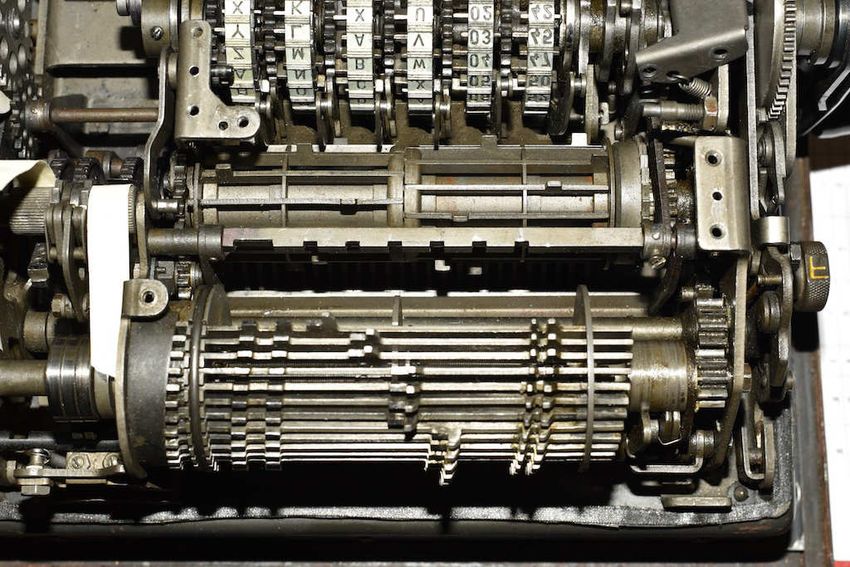
SG-41

Contents
   Abstract                                        3
   Introduction                                    5
        Pseudo-random number generator             6
   Operation                                       9
        Internal Key                               9
        External Key                               9
        Ciphering and deciphering                  9
   Pin-wheels                                     11
   Print head                                     13
        Encryption                                13
        Decryption                                13
   Wheel stepping                                 15
        Hagelin pin-and-lug machines until 1943   15
        Schlüsselgerät 41                         15
   Order of events                                16
   Creation of the PRN                            18
        Horizontal movement of the bars           19
        Sensing arms                              20
        Inactive pin                              21
        Active pin                                21
        Inversion                                 21
   Simulation                                     22
   Conclusions                                    24
   About the authors                              25
   References                                     25
        Links                                     24

Klaus Kopacz & Paul Reuvers                            3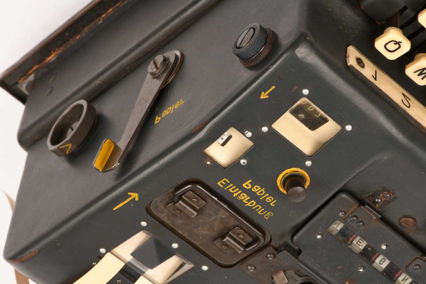
Figures
    1    IPO-model                                                                                  5
    2    Keyboard layout                                                                            5
    3    Pin-wheel seen from the left and front                                                     6
    4    The six pin-wheels and the yellow release button                                           6
    4    Overview of the controls and features                                                      7
    5    Left side of the SG-41                                                                     8
    6    Right side of the SG-41                                                                    8
    7    Sensing position on the pin-wheel (seen from the left side)                               11
    8    Example of a bitmask of the first five wheels                                             11
    9    Example of an inverted bitmask                                                            11
    10   Print head during encryption (left) and decryption (right)                                13
    11   Sensing positions on the pin-wheels (seen from the left side)                             15
    12   Order of events represented as the hours of a clock                                       17
    13   Bar with a lug at the position of pin-wheel 1                                             18
    14   Top view of the cage with the sideways movable bars                                       18
    15   Value of each wheel (bitmask)                                                             19
    16   Sliding bar shown at different pisitions whilst the cage revolves                         19
    17   Three possible positions of a bar                                                         20
    18   Sickle-shaped sensing arms                                                                20
    19   Behavior when wheel 6 = '0' (left) and when wheel 6 = '1' (right)                         21
    20   HELL H-54 (left) and Hagelin CX-52 (right)                                                22

Tables
    1    Layout of the pin-wheels                                                                  10
    2    Layout of the print head                                                                  12
    3    Examples of encryption and decryption                                                     12
    4    Chronological order of events                                                             16
    5    Pin-settings (example)                                                                    22
    6    Wheel positions when encrypting the given plaintext (PT) into ciphertext (CT)             23

4                                                                                        © Copyright 2021, Crypto Museum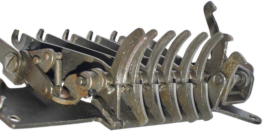
SG-41
Abstract
This paper describes the exact operation of Schlüsselgerät 41 (cipher machine 41), also known as the SG-41 or the Hitlermühle
(Hitler mill), and explains the complex order and timing of the events that take place when a text is enciphered. The authors
believe that this is the first time that some of the properties of this machine are revealed. A comparison is made with the
contemporary and similar Hagelin M-209 and BC-38 machines, and it is shown that the SG-41 was more advanced in several
ways. Furthermore, the authors present the wheel positions for a finite number of steps, along with the plaintext, the ciphertext
and the required settings. The strength of the cipher and possible cryptanalytic attacks will not be discussed here. This paper is
largely the result of the work of Klaus Kopacz, carried out whilst restoring a broken SG-41, whilst Paul Reuvers is responsible
for the English translation, the drawings, additional descriptions and some of the photographs.
Introduction
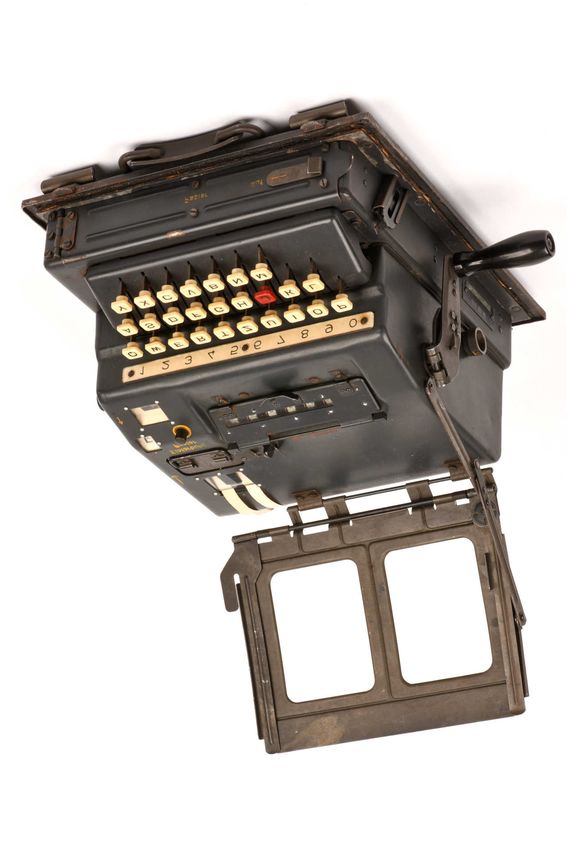
Schlüsselgerät 41 (German: cipher machine 41), commonly known as the SG-41 or the Hitlermühle (German: Hitler mill), was
a mechanical cipher machine, developed and built during World War II (WWII) by Wanderer Werke in Siegmar Schönau,
known today as Chemnitz (Germany). From 1943 to 1945 it was used by the German war machine — in particular by the
German Intelligence Service, the Abwehr. The SG-41 is a so-called pin-and-lug cipher machine, and shows great resemblance to
the Hagelin cipher machines of the era. Nevertheless, there are significant differences.
There are two versions of the machine: (1) the basic SG-41, with 26 keys for the Latin alphabet (A-Z) and (2) the SG-41Z,
with 10 numbered keys (0-9), suitable for numeric messages only. The SG-41Z was used by the Wetterdienst (weather service) of
the Luftwaffe (German Air Force), and will be described in a separate article. The current paper only describes the basic SG-41.
Input Process Output
Keyboard Cipher Printer
Figure 1 – IPO-model
Like all processing devices, the SG-41 consists of three basic elements: (1) a keyboard for the input, (2) a mechanical pseudo-
random number generator (PRNG) for processing the text (the actual encryption or 'cipher'), and (3) a printer for the output.
The keyboard has 26 keys that are marked with the uppercase letters of the Latin alphabet (A-Z) in the German layout. All
letters are black on a white key top, except for the letter 'J', which has a red key top. In the plaintext it is automatically replaced
by a space (blank). As the letter 'J' cannot be used in the plaintext, it has to be substituted by the letter 'I'. Behind the upper
row of keys is a label with the numerals 1-9 and 0. It allows the keys of the upper row (Q...P) to be used for numbers after the
user has entered a predefined shift-sequence. To switch back to letters, the user has to enter a predefined unshift-sequence.
Figure 2 – Keyboard layout
When encrypting or decrypting, one of the print heads is first rotated to the selected letter. The letter is then printed onto a
paper strip, after which all print heads are rotated an arbitrary number of steps and the enciphered letter is printed on another
paper strip. The arbitrary number of steps is determined by the mechanical pseudo-random number generator (PRNG).
After entering a letter on the keyboard, the user has to rotate the hand crank at the right side of the machine by one full
revolution. This causes the letter to be encrypted or decrypted, depending on the selected mode of operation. At the end of the
revolution, the plaintext and ciphertext letters have been printed onto individual paper strips, and the PRNG is set to its next
state. At the same time, the output letter is shown in a window.
Klaus Kopacz & Paul Reuvers 5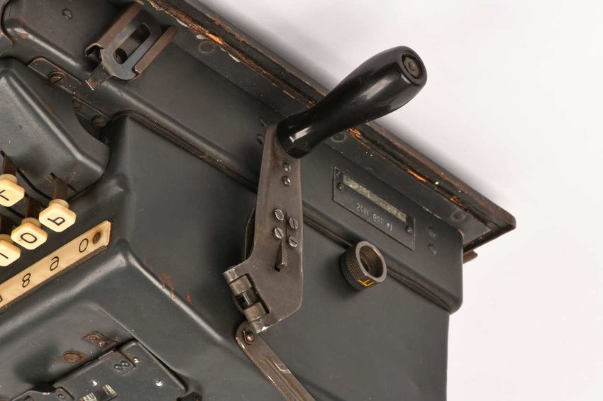
Pseudo-random number generator
The PRNG uses six pin-wheels, each with a different number of segments, plus a rotating drum, or cage, with horizontally
movable slide bars that multiply the value of the current pin-wheel with the presence of an active pin, and adds it to a running
total. Each pin-wheel has a series of pins on its circumference, equal to the number of segments on the wheel. Each pin can be
shifted to the left (inactive) or to the right (active). These states are also known as '0' (inactive) and '1' (active). The state of the
pins can be programmed in situ. Resetting all pins to the inactive state (0), requires the F/L switch to be set to the 'L' position,
the key 'Löschen' to be held down, and the crank to make 25 full revolutions. This procedure will be described later.

                                        Inactive

                                                           Active

                          25
                                                                     Figure 3
                                                                     Pinwheel seen from the left and front
                                                                     showing the inactive (left) and active (right) state

The Basic Setting of the 144 pins, also known as the Internal Key or Daily Key, allows 2144 different combinations, which is
equivalent to approx. 2.2 × 1043. In addition, the six pin-wheels must be set to their initial position before encrypting or
decrypting a text. This is known as the External Key, or Message Key. There are 25 × 25 × 23 × 23 × 24 × 24 = 190,440,000
possible combinations for the External Key.
The pseudo-random number (PRN), which is used to encrypt or decrypt a letter, is built by the PRNG from the state of the
pins at the circumference of the six pin-wheels, at a given position. In this process, the 6th wheel (i.e. the rightmost wheel)
drives an inverting function, which was a novely as it had never been implemented in a comparable machine before. This
function is also known as the complementary feature.
The stepping of the six pin-wheels evolves in four stages, driven by the state of the pins of all six pin-wheels, sensed at a specific
position on the circumference of the wheels. The ideas of the pin-wheels, the cylindrical cage with sideways movable bars, and
the circular print head, were clearly 'borrowed' from contemporary Hagelin machines like the M-209 and the BC-38. It should
be noted however, that the wheel stepping and the generation of the PRN are significantly improved in the SG-41.

                                    Figure 4 – The six pin-wheels and the yellow release button

6                                                                                                © Copyright 2021, Crypto Museum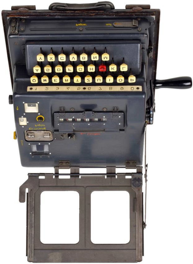
SG-41

The machine has a built-in double printer, that produces the output on two narrow paper strips, with the plaintext always on
the right, and the ciphertext always on the left. This fixed assignment of the printers is accomplished by shifting the print head
– which has four letter-rings – under control of the V/E switch (V = Verschlüsseln = encrypting, E = Entschlüsseln = decrypting).
This is an improvement over the Hagelin BC-38. The output of the ciphertext printer (left) is automatically formatted into
five-letter groups, that are separated by a space. In addition, the paper of the leftmost printer can be advanced in fixed steps
with a lever – marked 'Papier' (paper) – at the left side of the machine.
When loading or positioning the paper strips, the key marked 'Papier' (paper) on top of the machine can be pressed to release
the mechanism, so that the paper strip can be moved freely. At the bottom of the machine is a drawer that holds the two paper
supply spools: one for the plaintext and one for the ciphertext.
When sending a message, the sheet with the plaintext can be placed in a hinged copy holder on top of the machine. When
entering a text, a resettable counter at the top surface of the machine counts the number of encrypted letters. Also at the top
surface is a removable ink cartridge with four ink rolls, that can be inserted in two ways, marked '1' and '2'. In each position,
two of the ink rolls are placed before the print head. The other two are spares and become active when the cartridge is reversed.

                                                                                                    Copy holder

          Paper output
           Ink catridge                                                                             Reset pins
        Paper advance                                                                               Pin-wheel window
              V/E knob
          Output letter                                                                             F/L knob
         Paper release
        Letter counter
         Counter reset                                                                              Crank

                                                                                                    Space character ('J')

                                                                                                    Screwdriver

                                                                                                     Paper supply drawer

                                                     Carrying handle

                                        Figure 5 – Overview of the controls and features

Klaus Kopacz & Paul Reuvers                                                                                                      7
Figure 6 – Left side of the SG-41

    Figure 7 – Right side of the SG-41

8                                        © Copyright 2021, Crypto Museum
SG-41
Operation
Internal Key
Each pin-wheel has a fixed number of segments, or positions. For each position there is a pin on the side of the wheel, that can
be shifted to the left (inactive) or right (active). Before setting the Internal Key, all 144 pins must be reset (i.e. set to the left).
During the reset procedure, the cage and the printer will be disabled temporarily. Resetting goes as follows:
• Set the F/L knob to the 'L' position (L = Löschen = clear).
• Release the handle marked 'Löschen', shift it to the left and hold it in this position.
• Make at least 25 full revolutions with the crank until the display reads '025'.
• Release the 'Löschen' handle.
• Reset the character counter by rotating its knob until the counter reads '000'.
• Set the F/L knob back to the 'F' position (F = Funktion = operate).
All 144 pins are now set to the inactive state ('0'). The active pins can now be set as follows:
• Open the hinged window over the pin-wheels.
• Push the yellow-marked release button to the right of the pin-wheels (see Figure 4).
• The wheels can now be rotated freely and the relevant pins can be set to the active state (right).
The wheels will automatically be locked again as soon as the crank is operated.
External Key
Before encrypting or decrypting a text, the six pin-wheels must be set to the current External Key, also known as the Message
Key. The segments of the leftmost four wheels are marked with letters, whilst the rightmost two have numbers.
• Place the crank in the lowest position (i.e. at 6 o'clock).
• Open the hinged window over the pin-wheels.
• Push the yellow-marked release button to the right of the pin-wheels.
• Turn each rotor so that the desired letter or number will be visible through the window.
• Close the window when ready.
Ciphering and deciphering
Encryption and decryption of a message goes as follows:
• Set the F/L knob to 'F'.
• Push and hold the knob marked 'Einfärbung Papier'.
• Pull-out several centimeters of each of the paper strips, and tear them off.
• Release the knob.
• Set the V/E knob to 'V' for encryption, or 'E' for decryption.
• Reset the character counter.
• Enter a letter on the keyboard and turn the crank clockwise until it locks again in the 6 o'clock position.
• Repeat the above step until all letters of the message have been processed.
Each time a letter is entered and the crank is rotated, the plaintext letter and the ciphertext letter are printed. A space is inserted
automatically after each five-letter group in the ciphertext only. If necessary, group spaces can be inserted manually by operating
the 'Papier' lever (see Figure 6). When the message is complete, press the 'Papier' knob and pull out the paper strips as far as
necessary, before tearing them off.
Klaus Kopacz & Paul Reuvers 91 2 3 4 5 6
25 25
25 Z Z 24 24
24 Y Y 23 23 24 57
23 X X X X 23 55
22 W W W W 22 52
21 V V V V 21 50
20 U U U U 20 47
19 T T T T 19 45
18 S S S S 18 42
17 R R R R 17 40
16 Q Q Q Q 16 37
15 P P P P 15 35
Window 14 O O O O 14 32
Sensed
13 N N N N 13 30
12 M M M M 12 27
11 L L L L 11 25
10 K K K K 10 22
9 I I I I 09 20
8 H H H H 08 17
7 G G G G 07 15
6 F F F F 06 12
5 E E E E 05 10
4 D D D D 04 07
3 C C C C 03 05
2 B B B B 02 02
1 A A A A 01 00
Value 1 2 4 8 10 inv.
Pin sensing offset +8 +8 +8 +8 +8 +8
Table 1 – Layout of the pin-wheels
10 © Copyright 2021, Crypto MuseumSG-41
Pin-wheels
At the heart of the pseudo-random number generator (PRNG) are the six pin-wheels that are located below a hinged window at
the top, numbered 1 to 6 from left to right. The wheels are fitted permanently on an axle and cannot be swapped. Each wheel
has a different number of segments, or positions: 25, 25, 23, 23, 24, and 24 respectively. Each segment is marked with a letter
or number, in ascending order from bottom to top, as shown in Table 1. When stepping, the front face of a wheel moves down-
wards, so that the numbers and letters pass by the window in ascending order.
+ 8 positions
Letter visible in the window
Sensing position for
print head rotation
FRONT
REAR
25
pins Stepping direction
Figure 8 – Sensing position on the pin-wheel (seen from the left side)
When building the pseudo-random number (PRN) the state of a pin is sensed at a certain position on the wheel, which is
different from the position shown in the window. This position is 8 steps above the letter that is shown in the window, as
illustrated in Figure 8. A few examples that are highlighted in Table 1:
• When wheel 1 shows the letter 'W' in the window (position 22), the state of the pin at position (22 + 8) modulo 25 = 5
is sensed, which is at the letter 'E'.
• When wheel 5 shows the number 10 in the window, the state of the pin at position (10 + 8) modulo 24 = 18 is sensed.
When a sensed pin of wheels 1 to 5 is active, the value of that wheel is added to a running total. These values are 1, 2, 4, 8 and
10 respectively. In many respects this behaves like a binary bitmask, albeit with different values for the bits. For example: if the
sensed pins on wheels 1, 3 and 4 are active, the bitmask can be written as 10110 and the total value will be 1 + 4 + 8 = 13.
Likewise, if all pins are active (bitmask 11111), the total value will be 1 + 2 + 4 + 8 + 10 = 25.
1 2 3 4 5
1 0 1 1 0
1 2 4 8 10
Figure 9 – Example of a bitmask of the first five wheels
When the sensed pin of wheel 6 is active, the bitmask will be inverted. For example: if the bitmask was 10110 and the sensed
pin of wheel 6 is active (i.e. '1'), the bitmask becomes 01001, which results in a total value of 2 + 10 = 12.
1 2 3 4 5
0 1 0 0 1
1 2 4 8 10
Figure 10 – Example of an inverted bitmask
Klaus Kopacz & Paul Reuvers 11Ciphertext Plaintext Encryption Decryption
1 2 3 4 2 4 1 3
26 E I I E I E E I
25 U D D U D U U D
24 Y Z Z Y Z Y Y Z
23 L Q Q L Q L L Q
PRN-shift
22 C N N C N C C N
21 O X X O X O O X
20 S M M S M S S M
19 G T T G T G G T
18 V B B V B V input V B
17 J W W J W J J W
16 W J J W J W W J
15 B V V B V B B V
14 T G G T G T T G
13 M S S M S M M S
12 X O O X O X X O
PRN-shift
11 N C C N C N N C
10 Q L L Q L Q Q L
9 Z Y Y Z Y Z Z Y
8 D U U D U D D U
7 I E E I E I input I E
6 F P P F P F F P
5 H A A H A H H A
4 R K K R K R R K
3 K R R K R K K R
2 A H H A H A A H
1 P F F P F P P F
Output
Input
Table 2 – Layout of the print head Table 3 – Examples of encryption and decryption
12 © Copyright 2021, Crypto MuseumSG-41
Print head
The print head consists of four cylindrical rings, mounted on a single axle. The layout of the four rings – numbered 1 to 4 – is
given in Table 2. The outer two rings (1 and 4) are identical, just like the inner two rings (2 and 3). When the print head is
moved by the Pseudo-Random Number Generator (PRNG), the letters on the front face of the print head move downwards,
and appear at the print position as defined in Table 2, reading the table from bottom to top.
Each letter ring has the 26 letters of the Latin alphabet in a fixed scrambled order. The order of the letters on the inner rings is
the reverse of the order of the letters on the outer rings. In Table 2, three letters are highlighted to illustrate the reversed order. It
allows the machine to encrypt and decrypt without changing the inner mechanics. Had reverse letter rings not been used, the
rotational direction of the print head had to be reversed during decryption. The print head is shown in Figure 11.
Ciphertext
Ciphertext
Plaintext
Plaintext
1 2 3 4 1 2 3 4
Encryption Decryption
Ink rollers Ink rollers
Figure 11 – Print head during encryption (left) and decryption (right)
The V/E knob – used to select between encryption (V) and decryption (E) – only shifts the print head sideways, so that the
plaintext is always printed on the right paper strip, and the ciphertext is always printed on the left paper strip. A similar system
– with three letter rings – was used in the Hagelin BC-38. Later Hagelin machines, such as the C-446 and CX-52, had only
two letter rings on the print head, which could not be shifted sideways. On the Hagelin machines the C/D knob – used to
select between encryption (C) and decryption (D) – enables the 5-letter group spacing only in encryption mode.
Examples for encrypting and decryption a letter, are given in Table 3. In the examples, the PRNG is assumed to have produced
the pseudo-random number (PRN) 8, which means that the print head is rotated by 8 positions as part of the encryption/
decryption process. The machine is assumed to be in the same state for both examples, which are further explained below.
Encryption
The V/E knob is set to 'V'. When encrypting the letter 'V', the user presses the V-key on the keyboard and starts turning the
crank. The print head is turned to position 18 and the letter 'V' is printed on the rightmost paper strip. Without the PRNG,
the letter 'B' would have been selected as the ciphertext. When continuing to turn the crank however, the print head will be
turned by a number of positions – 8 in this case – as a result of the PRN. It then stops at position 26 and prints the letter 'I' on
the leftmost paper strip.
Decryption
The V/E knob is set to 'E'. When decrypting the letter 'I', the user presses the I-key on the keyboard and starts turning the
crank. The print head is turned to position 7 and the letter 'I' is printed on the leftmost paper strip. Without the PRNG, the
letter 'E' would have been selected as the plaintext. When continuing to turn the crank however, the print head will be turned
by a number of positions – 8 in this case – as a result of the PRN. It then stops at position 15 and prints the letter 'V' on the
rightmost paper strip.
Klaus Kopacz & Paul Reuvers 13This page is intentionally left blank 14 © Copyright 2021, Crypto Museum
SG-41

Wheel stepping

Hagelin pin-and-lug cipher machines until 1943
Up to 1943, the well-known mechanical Hagelin pin-and-lug machines, also known as the C-machines, used a cylindrical
drum with sideways movable bars at the heart of its PRNG. This drum is also known as the 'cage'. It was based on a money
exchange machine that Boris Hagelin had developed in the early 1930s [1]. The function of the cage was the addition of
different values based on a bitmask. For every active '1' bit in the bitmask, the value of that bit was added to a running total. In
the C-machines the sum of the active bit values was used to generate a variable rotation of the print head.
Each pin-wheel has a different number of segments, or positions, and is rotated by one position each time a letter is encrypted.
For each encrypted letter, the cage makes one full revolution (360°). Active pins of a pin-wheel are sensed by an internal lever,
and causes a bar that carries a lug at that position, to shift from right to left, were it engages a cogwheel, which in turn rotates
the print head by one position. Some C-machines had fixed lugs on the bars, whereas others had configurable ones. Each bar
arrives at the cogwheel in the rightmost (inactive) or leftmost (active) position. All pin-wheels contribute with their sensed pins
(in combination with their value) to the creation of the PRN, which is the number of positions the print head is rotated.

Schlüsselgerät 41
Stepping of the pin-wheels of the SG-41 is controlled by the rotation of the crank in four phases (I, II, III and IV) and is based
on the state of the pins at certain positions on the circumference of the pin-wheels. Two of the stepping phases are carried out
before the encryption of a letter. The other two stepping phases are carried out after the encryption of a letter and will therefore
have an effect on the next letter that is to be encrypted. This results in a complex stepping pattern of 1 to 4 positions for pin-
wheels 2 to 6, and 1 or 2 positions for wheel 1.
                                                       + 8 positions
                                                                                     Letter visible in the window

        Sensing position for PRNG
        Causes print head rotation                                                       – 5 positions
                                                                                            FRONT
                                REAR
                                                                 25

                                     pins                                                  Sensing position
                                                                                         for wheel stepping

                                                                         Stepping direction
                             Figure 12 – Sensing positions on the pin-wheel (seen from the left lide)
The sensing position of the pins, used by the stepping mechanism, is not the same as the one that is used by the cage to
calculate the rotation of the print head. For the stepping mechanism, the state of the pins 5 positions below the one that is
shown in the window are sensed, as illustrated in Figure 12 (the blue arrow). These positions are latched before the first two
stepping phases (I and II) are executed. Before the third stepping phase (III), the pins are re-sensed, which is after the wheels
might have moved. In the fourth phase (IV), all wheels are stepped by one position.

Klaus Kopacz & Paul Reuvers                                                                                                         15
Order of events
After entering a letter, the crank has to make one full revolution (360°) to get the enciphered letter. The crank operates the
internal mechanism, causes the PRNG to create a PRN, rotates the print head, (conditionally) steps the pin-wheels, and causes
the input and output letters to be printed onto two paper strips. Several events take place during the 360° revolution, at
different positions of the crank. In order to explain the operation of the SG-41 and the order in which the events take place, the
full revolution is divided into 12 segments, named after the hours of a clock, as illustrated in Figure 13. The same events are
listed in chronological order in Table 4.
In rest, the crank is in the 6 o'clock position and is locked until a key is pressed. Once a key is pressed, the crank is released and
must be turned 360° clockwise to encrypt the letter, after which the crank is locked again. Immediately at the start, between 6
and 7 o'clock, the print head driving cylinder is wound up. It has several lugs at its circumference – one for each letter of the
alphabet – and is visible in Figure 15. When the cylinder is released at 7 o'clock, it causes the print head to rotate until one of
its lugs is stopped by the raised lever of the currently pressed key. At this point, the print head stops at the selected letter.
Crank position Revolving cage (adder) Pin-wheel stepping Remark
In rest Pin-sensing at 5 positions
6 o’clock down on each wheel
1 6-7 o’clock Driving cylinder wound up The pin-state at -5 is latched Key pressed, crank released
2 7-8 o’clock Driving cylinder released Print head stops at input letter
3 7-10 o’clock Paper transport
4 10-11 o’clock When pin of wheel 6 is ‘1’, Wheel 1 never steps at this
each of the wheels 1 to 5 of phase
which the pin is ‘1’ causes the
wheel to its right to make a
single step
5 11-12 o’clock When pin of wheel 6 was ‘1’
before 10 o’clock position, all
wheels make a single step
6 1 o’clock The pin-state at +8 is latched The pin-state at -5 is relatched Key released
7 2 o’clock The input letter is printed
8 2-4 o’clock Cage turns and adds the values
of the sensed pins (PRN),
causing the print head to step
by positions
9 4-5 o’clock Cage still turns but no longer Each of the wheels 1 to 5 of Wheel 1 never steps at this
rotates the print head which the pin is ‘1’, causes the phase
wheel to its right to make a
single step
10 5 o’clock The output letter is printed
11 5-6 o’clock Wheels 1 to 6 all make a
single step
12 6 o’clock Crank locked
Table 4 – Chronological order of events
16 © Copyright 2021, Crypto MuseumSG-41
If pin of wheel 6 was '1' at 10 o'clock position,
all pin wheels are stepped by one position
If the pin of wheel 6 is '1': Key released
each of the wheels 1 to 5
of which the pin is '1', 12
causes the wheel to
its right to step by 11 1
one position Input letter printed
10 II 2
I
9 3
Paper strip The cage rotates and
advances III
builds the PRN, which
8 4 results in a rotation of
rotation IV the print head
7 5 Each of the wheels 1 to 5 of
6 which the pin is '1', causes
the wheel to its right to step
Print head locks by one position
at input letter Key pressed
Crank released Output letter printed
Driving cylinder wound up All wheels are stepped by one position
Figure 13 – Order of events represented as the hours of a clock
Stepping of the pin-wheels at 10-11 o'clock (Phase I) and 11-12 o'clock (Phase II) takes place before the PRN is generated and
the print head is rotated. This means that they have an effect on the encryption of the current input letter. The last stepping
phases, at and 4-5 o'clock (Phase III) and 5-6 o'clock (Phase IV), take place after the letter has been encrypted, and therefore
only have an effect on the next letter that is to be encrypted.
Stepping of the individual wheels – e.g. at 10-11 o'clock (Phase I) – does not take place sequentially, but in parallel. The
decision to step a wheel (or not) has been sensed and latched earlier and is carried out in parallel at this stage. In other words: if
a pin of a given pin-wheel (n) is active ('1'), the wheel to its right (n+1) makes a single step, regardless of whether or not wheel
(n) was stepped itself by the wheel to its left (n-1).
For wheel stepping, the state of the pins of the pin-wheels is sensed at 5 positions under the window and memorised (latched)
for the 10-11 o'clock (Phase I) and 11-12 o'clock (Phase II) stepping phases. Before the 4-5 o'clock stepping phase (III), the
state of the pins is re-sensed.
Stepping at 10-11 o'clock (Phase I) only takes place if the sensed pin of wheel 6 is active ('1'). It is possible that wheel 6 is
stepped by wheel 5 (if wheel 5 had an active pin) but this has no effect on the 10-11 o'clock (Phase I) and 11-12 o'clock (Phase
II) stepping phases, as the states of the sensing pins have been latched earlier.
Klaus Kopacz & Paul Reuvers 17Creation of the PRN
An input letter is encrypted by rotating the print head an arbitrary number of steps, resulting in an output letter that is printed
onto a paper strip. The arbitrary number of steps is a pseudo-random number (PRN) between 0 and 25, that is generated by
sensing the state of the pins at a certain position on the circumference of six irregularly stepping pin-wheels. If a pin is active,
the value of that wheel is added to a running total. This is done by a cylindrical drum – known as the 'cage' – which is in fact a
mechanical adder. The cage has 25 horizontally movable bars, each of which has a different set of lugs at one of its long sides.
Figure 15 shows a top view of the machine with its cover taken off, in which the cage and the pin-wheels are clearly visible.
pin-wheels
1 2 3 4 5 6
Transport lug
Figure 14 – Bar with a lug at the position of pin-wheel 1
The lugs are positioned in such a way that each of them can interact with the sensing arm that determines the state of a pin of a
particular pin-wheel, 8 positions above the window. Figure 14 shows a bar with a lug at the position of wheel 1. The possible
positions for lugs that can interact with the sensing arms of wheels 2, 3, 4 and 5 are shaded. The lugs for wheel 6 are different,
as they are used to invert the bitmask of the calculated sum. When the cage makes one full revolution, all 25 bars are passed by
the pin-wheels. The total number of lugs that pass by a particular pin-wheel, determines the value of that wheel. As the lugs are
fixed in place — they are not configurable — the value of each wheel (i.e. the sum of the lugs) is fixed as well.
Printer Sideways movable bars with lugs
Print head driving cylinder
Cylindrical ramp Lugs Pin-wheels
Figure 15 – Top view of the cage with the sideways movable bars
18 © Copyright 2021, Crypto MuseumSG-41
In the SG-41, the lugs on the bars are chosen in such a way that the wheels have the values shown in Figure 16.
• If wheel 1 has an active pin, the print head is rotated by 1 step
• If wheel 2 has an active pin, the print head is rotated by 2 steps
• If wheels 3, 4 or 5, have an active pin, the print head is rotated 4, 8 and 10 steps respectively
• If wheel 6 has an active pin, the state of pins 1 to 5 is inverted (i.e. active becomes inactive and vice versa)
A few examples:
• If the state of the sensed pins of the six pin-wheels is 100110, the sum is calculated as 1 + 8 + 10 = 19.
• If the state of the pin-wheels is 100111, the value is inverted (i.e. 011000) and the sum is 2 + 4 = 6.
• If the state of the pin-wheels is 100100, the sum is calculated as 1 + 8 = 9.
In the case of these examples, the print head will be rotated by 19, 6 or 9 steps respectively.
1 2 3 4 5 6
1 2 4 8 10 inv.
Figure 16 – Value of each wheel (bitmask)
Horizontal movement of the bars
The horizontal movement of the bars in the cage of the SG-41 is different from the movement of the bars in a Hagelin cipher
machine like the M-209 and BC-38. Instead of two possible positions (in the Hagelin machines) the bars of the SG-41 have
three possible positions. Figure 17 shows that each bar has a spring that pulls it to the left. At the left side of the cage is a static
cylindrical ramp that engages with the transport lug (i.e. the leftmost lug) of each bar. When rotating the cage, the ramp pushes
the bars to the right. Figure 17 shows a bar with a extra lug at the position of wheel 1, at various angles of rotation of the cage.
As soon as a bar reaches the end of the ramp, it is pulled to the far left by its spring, and the transport lug (i.e. the leftmost lug
on each bar) engages with a small cogwheel that can rotate the print head by one position. The sensing arms of the pin-wheels
are shaped in such a way that they can interact with the corresponding lugs on the bars. Depending on their state, they may
(partially) restrict the movement of the bars. In figure 17, the transport lug of the bar is engaged with the cogwheel.
Static cylindrical ramp Bar shown at different positions Common axle
Current bar
Transport lug Lug at the position of wheel 1
Cogwheel that causes the print head to make a single step
End of the ramp
Figure 17 – Sliding bar shown at different positions whilst the cage revolves
Klaus Kopacz & Paul Reuvers 19As the lugs on the bars have a lowered and a raised part (and may even be absent), there are three possible positions in which
the bar can be locked by a lever. These states are shown in Figure 18. If the lug is absent, or the lever is not engaged, the bar is
pulled to the leftmost position (1) and the transport lug overshoots the cogwheel. If the lever catches the raised part of the lug,
the bar is locked in the middle position (2) and the transport lug engages with the cogwheel. This is the only situation in which
the print head can make a step. If the lever catches the lowered part of the lug, the bar is locked in the rightmost position (3)
and the transport lug does not reach the cogwheel.
1 Lever not Bar in the leftmost position,
engaged overshooting the cogwheel
2 Lever catching Bar in the middle position,
raised part of lug engaged with the cogwheel
3 Lever catching
lower part of lug
Bar in the rightmost position,
not engaged with the cogwheel
Figure 18 – Three possible positions of a bar
Sensing arms
In order to carry the state of the sensed pin of a particular pin-wheel on to the bars in the cage, a complex construction of arms
and sickle-shaped levers – pivoting on a common axle – is mounted between the pin-wheels and the cage. This construction is
shown in Figure 19. The upper part of the sickle-shaped levers can interact with the bars during phase 1 of the cage rotation.
The lower part of the levers is somewhat recessed and can interact with the bars during phase 2 of the cage rotation. If a pin-
wheel has an active pin, the corresponding sickle-shaped lever is pushed forward by the sensing arm.
6 5 4 3 2 1
Phase 1
Phase 2
Sensing arms Sickle-shaped levers
Figure 19 – Sickle-shaped sensing arms
20 © Copyright 2021, Crypto MuseumSG-41
Inactive pin
If the pin of a sensed pin-wheel is inactive ('0'), the sickle-shaped lever is not pushed forward. During phase 1 of the cage
rotation, the upper part of the lever catches the raised part of the corresponding lug on the current bar. This locks the bar in the
middle position (2). During phase 2 of the cage rotation, the lower – recessed – part of the lever does not engage with the lug
and allows the bar to be pulled to the leftmost position (1), in which case it overshoots the cogwheel. This means that in this
situation, the print head is not rotated.
Active pin
If the pin of a sensed pin-wheel is active ('1'), the sickle-shaped lever is pushed forward. During phase 1 of the cage rotation, the
upper part of the lever catches the deeper part of the corresponding lug on the current bar. This locks the bar in the rightmost
position (3). During phase 2 of the cage rotation, the lower – recessed – part of the lever catches the raised part of the lug and
locks the bar in the middle position (2), coupling the bar with the cogwheel. In this situation, the bar drives the cogwheel,
which in turn causes the print head to make a single step.
Inversion
The rightmost pin-wheel (wheel 6) drives the inversion-function, which is carried out directly by the cage. If wheel 6 has an
active pin, the state of the pins of wheels 1 to 5 is inverted. This means that an active pin becomes inactive and vice versa. In
this case, the sickle-shaped lever of wheel 6 is pushed forward. During phase 1 of the cage rotation, this has no effect, as the
upper part of lever 6 is recessed. In phase 2 of the cage rotation however, the lower part of the lever catches one of the two small
lugs at the far right of each bar, which locks the bar in the state it had during phase 1.
Figure 20 shows the four possible situations for wheel 1 only — with an active or inactive pin, with and without inversion. For
each situation, phase 1 and phase 2 of the cage rotation are shown. When wheel 6 is inactive, the bar follows the state of the
corresponding pin-wheel. This situation is shown in the left half of Figure 20. When wheel 6 is active, the bars are locked in
their phase 1 state, by the phase 2 part of the sickle-shaped lever of wheel 6, that has been pushed forward. This situation is
shown in the right half of Figure 20.
Wheel 6 inactive ('0') - no inversion Wheel 6 active ('1') - state of wheels 1-5 is inverted
Wheel 1 inactive ('0')
Phase 1 Phase 1
1 6 1 6
Phase 2 Phase 2
1 6 1 6
Wheel 1 active ('1')
Phase 1 Phase 1
1 6 1 6
Phase 2 Phase 2
1 6 1 6
Figure 20 – Behaviour when wheel 6 = '0' (left) and when wheel 6 = '1' (right)
Klaus Kopacz & Paul Reuvers 21Simulation
In order to verify the operation of the SG-41 as explained in the previous chapters, a simple simulation was made in a spread-
sheet. It was used to check the stepping mechanism, the order of events and the encryption algorithm, for a finite number of
steps. It is the intention of the authors to make this spreadsheet available on the Crypto Museum website in due course. As an
example we will show the encryption of a 32-character plaintext, using a given setting of the machine. First, set the pins as
specified in Table 5, in which '0' means 'left' and '1' means 'right'. Next, set the wheels to the start position highlighted in red:
A B C D 01 00
Table 6 shows the position of each wheel before encrypting a given 32-character plaintext (PT) – shown in the yellow column.
If all goes well, it should produce the specified ciphertext (CT) – shown in the blue column:
PT: SCHLUESSELGERAETVIEREINSWANDERER
CT: IHEPLRETQSDSNDCWHPIVVGLYMHOWSJQS
1 2 3 4 5 6
1 A 0 A 0 A 1 A 0 01 0 00 0
2 B 0 B 1 B 1 B 1 02 0 02 1
3 C 0 C 1 C 0 C 0 03 1 05 1
4 D 1 D 0 D 0 D 0 04 0 07 0
5 E 1 E 1 E 1 E 1 05 0 10 0
6 F 0 F 0 F 0 F 0 06 1 12 1
7 G 1 G 0 G 0 G 0 07 0 15 1
8 H 0 H 1 H 1 H 0 08 0 17 0
9 I 1 I 0 I 0 I 1 09 1 20 0
10 K 1 K 0 K 0 K 1 10 0 22 1
11 L 0 L 0 L 0 L 1 11 1 25 1
12 M 0 M 0 M 1 M 0 12 0 27 0
13 N 0 N 1 N 0 N 1 13 0 30 0
14 O 1 O 0 O 0 O 0 14 0 32 0
15 P 0 P 1 P 1 P 0 15 0 35 1
16 Q 0 Q 1 Q 0 Q 0 16 1 37 0
17 R 0 R 1 R 0 R 1 17 0 40 1
18 S 1 S 0 S 1 S 1 18 1 42 1
19 T 0 T 0 T 0 T 1 19 0 45 0
20 U 0 U 1 U 0 U 0 20 1 47 1
21 V 0 V 0 V 0 V 0 21 1 50 0
22 W 1 W 1 W 1 W 1 22 0 52 1
23 X 1 X 1 X 0 X 0 23 1 55 0
24 Y 0 Y 0 24 0 57 0
25 Z 1 Z 0
Table 5 – Pin-settings (0 = left, 1 = right)
22 © Copyright 2021, Crypto MuseumSG-41
Set the wheels to the start position shown in red at line 1 (A B C D 01 00). This is known as the Grundstellung (basic setting).
Enter the first letter of the plaintext (S) and turn the crank by one full revolution. This should yield the first letter of the cipher-
text (I). The wheels should now be in the positions specified at line 2 (C E G F 04 07). Now enter the second letter (C) and
turn the crank again. This should yield the second ciphertext letter (H). The window now shows D G H H 05 12. And so on.
Working simulators, that have been verified with these settings, are available for Python [5], Java [6] and BBC BASIC [7].
1 2 3 4 5 6 PT CT
1 A B C D 01 00 S I
2 C E G F 04 07 C H
3 D G H H 05 12 H E
4 E H K I 06 15 L P
5 G L O M 08 20 U L
6 H M P N 09 25 E R
7 K P S P 12 30 S E
8 L R T Q 14 32 S T
9 M S U R 16 37 E Q
10 O V A U 18 45 L S
11 P X C V 19 47 G D
12 R A F A 22 52 E S
13 T C I E 01 57 R N
14 U E L F 02 02 A D
15 V F M G 03 07 E C
16 W G N H 05 10 T W
17 X H P K 06 12 V H
18 Y K R L 08 15 I P
19 A M U O 10 22 E I
20 B N V Q 12 25 R V
21 D R A T 15 32 E V
22 E S B U 16 35 I G
23 G V F X 18 42 N L
24 H W H B 20 45 S Y
25 I X K C 21 47 W M
26 L B N F 23 55 A H
27 N E R I 01 02 N O
28 O F S L 02 07 D W
29 P H T M 03 12 E S
30 Q K V N 04 15 R J
31 S M A Q 07 22 E Q
32 T N B R 09 25 R S
Table 6 – Wheel positions when encrypting the given plaintext (PT) into ciphertext (CT)
Klaus Kopacz & Paul Reuvers 23Conclusions
In this paper we have shown that Schlüsselgerat 41 (SG-41) is based on the design principle of contemporary Hagelin machines
like the M-209 and BC-38, but that it contains a number of advanced features which were not available on other machines at
the time. We have presented a number of technical details about this machine that have not been available in the public domain
before, and we have explained the complex order and timing of the events that take place when a letter is enciphered. In
addition we have shown that the common understanding of the wheel stepping principle, namely that the wheels can step in
both directions, is incorrect [2]. The most important differences with the contemporary Hagelin machines are listed here:
• Irregular stepping of the cipher wheels, with complex timing
• Each wheel has two sensing positions: one for stepping the adjacent wheel and one for rotating the print head
• The sensing position for wheel stepping is re-sensed during the enciphering process
• Improved printer with fixed assignment and (optional) automatic spacing of 5-letter groups
• Inversion of the value generated by wheels 1 - 5 under control of wheel 6
The principle of irregularly stepping cipher wheels was later introduced by Hagelin on the CX-52 [3].
The inversion principle was used in a modified form in the HELL H-54, which was basically a clone of the CX-52. It was
produced for the German Army (Bundeswehr) by Hell in Kiel (Germany), under licence from Crypto AG (Hagelin). The
inversion principle was known as the 'Hüttenhain feature', and was named after Dr. Erich Hüttenhain who was the head of the
Zentralstelle für das Chiffrierwesen (ZfCh) — the German cipher authority. During WWII, Hüttenhain had been the head of
the cryptanalysis unit at OKW/Chi — the cipher department of the High Command of the German Wehrmacht (OKW) [4].
Figure 21 – HELL H-54 (left) and Hagelin CX-52 (right)
24 © Copyright 2021, Crypto MuseumSG-41
About the authors
1. Klaus Kopacz is a self-employed electronics engineer in Stuttgart (Germany). Over the years he has collected a wide range of
historical cipher machines, and has helped others to collect, maintain and restore such machines as well. His interests include
the technical operation of cipher machines and their historical context. He is particularly known for his Enigma Rebuild —
arguably the most accurate in its class — and his expertise in the restoration of Enigma and other cipher machines.
2. Paul Reuvers is a self-employed electronics engineer in Eindhoven (Netherlands), who has specialised in the development of
embedded software. He is also one of the curators of the collection of the Crypto Museum (Netherlands), which he co-owns
with Marc Simons. His interests include the technical and historical backgrounds of cipher machines, spy radio sets and related
equipment, as well as their restoration.
Acknowledgments
The authors would like to thank Niall McLaughlin for lending his SG-41 and allowing them to (partly) disassemble it. Thanks
are also due to Marc Simons, Bart Wessel, Hugh Coleman and several others for their helpful comments and suggestions.
References
[1] Boris Hagelin, Die Geschichte der Hagelin-Cryptos. Zug, Fall 1979. p. 23.
https://www.cryptomuseum.com/crypto/hagelin/files/hagelin_story_de.pdf
[2] Wikipedia, Schlüsselgerät 41 (visited 12 January 2021)
https://en.wikipedia.org/wiki/Schlüsselgerät_41
[3] Crypto Museum, Hagelin CX-52
https://www.cryptomuseum.com/crypto/hagelin/cx52/
[4] Crypto Museum, HELL H-54
https://www.cryptomuseum.com/crypto/hell/h54/
[5] Hugh Coleman, SG-41 Simulator in Python
https://github.com/hughcoleman/sg41
[6] George Lasry, SG-41 Simulator in Java
https://www.cryptomuseum.com/crypto/sg41/index.htm#sim
[7] Paul Reuvers, SG-41 Simulator in BBC BASIC
https://www.cryptomuseum.com/crypto/sg41/index.htm#sim
Links
• Crypto Museum, Schlüsselgerät 41
https://www.cryptomuseum.com/crypto/sg41/
Klaus Kopacz & Paul Reuvers 25This page is intentionally left blank 26 © Copyright 2021, Crypto Museum
You can also read