Technical Report Experimental testing of high capacity screwed connections in Douglas-fir CLT - Thomas Wright & Minghao Li
←
→
Page content transcription
If your browser does not render page correctly, please read the page content below
Technical Report

 Experimental testing of high capacity
       screwed connections in
           Douglas-fir CLT
                   Thomas Wright & Minghao Li

Date: 16-01-2021

Report: SWP-T119
TABLE OF CONTENTS

EXECUTIVE SUMMARY ................................................................................................................ 1
INTRODUCTION ............................................................................................................................ 2
PHASE 1 TESTS: CONNECTIONS WITH 50-100 KN CAPACITY .................................................. 3
  Test Program .............................................................................................................................. 5
  Results ........................................................................................................................................ 7
  Discussion .................................................................................................................................. 8
    Optimal threaded length of screw ............................................................................................ 8
    Suitability of 45 degree washers to this application ................................................................. 9
    Optimal Ratio of withdrawal to shear fasteners...................................................................... 11
PHASE 2 TESTS: CONNECTIONS WITH 300-700 KN CAPACITY .............................................. 13
  Test Program ............................................................................................................................ 15
  Results ...................................................................................................................................... 17
  Discussion ................................................................................................................................ 18
    Hold-down component test for previous wall testing .............................................................. 18
    Single sided vs double sided ................................................................................................. 18
    Optimal ratio of withdrawal to shear screws .......................................................................... 20
    Repairs.................................................................................................................................. 21
CONCLUSION .............................................................................................................................. 25
ACKNOWLEDGEMENTS ............................................................................................................. 27
REFERENCES ............................................................................................................................. 27

Disclaimer

This report has been prepared by University of Canterbury for Forest Growers Research Ltd (FGR) subject
to the terms and conditions of a research services agreement dated 1 July 2015.

The opinions and information provided in this report have been provided in good faith and on the basis that
every endeavour has been made to be accurate and not misleading and to exercise reasonable care, skill
and judgement in providing such opinions and information.

Under the terms of the Services Agreement, University of Canterbury’s liability to FGR in relation to the
services provided to produce this report is limited to the value of those services. Neither University of
Canterbury nor any of its employees, contractors, agents or other persons acting on its behalf or under its
control accept any responsibility to any person or organisation in respect of any information or opinion
provided in this report in excess of that amount.
EXECUTIVE SUMMARY
This report presents experimental results of high capacity hold-down connections in Douglas-fir
Cross Laminated Timber (CLT) using self-tapping screws installed with mixed angles (inclined and
90° angle to the timber surface).

This report consists of two experimental phases. In phase 1, a total of 28 small scale connection
tests (50-100 kN capacity) were performed to identify the optimal threaded length of screws under
withdrawal loads, the suitability of 45° washers to the mixed angle screw applications, and the
optimal ratio of inclined screws to 90° screws. In phase 2, a total of 27 large scale connection tests
(300-700 kN capacity) were performed to evaluate the performance of the mixed angle hold-downs
performed in a CLT shear wall system. The tests also investigated the difference between single
sided hold-downs and the double sided hold-downs, the optimal ratio between inclined and 90°
screws, and the reparability of mixed angle screw connections after severe damage.

It was found that:
    • Fully threaded screws can provide higher stiffness and more load carrying capacity per
        fastener, tensile failure of the screw must be avoided to allow their use in this style of
        connection.
    • The 45-degree washers evaluated are suitable for mixed angle screw connection type if
        proper detailing allows for the formation of a plastic hinge at the head of the withdrawal
        screw.
    • The ratio of 1:2 (number of withdrawal screws to number of shear screws) was found to be
        the optimum ratio (compared to 1:1 and 1:1.5).
    • Double sided horizontal hold-down tests provided significant displacement capacity
        performance benefits over a single sided test, as that was not well horizontally constrained.
    • Tests prove the suitability of mixed angle screw hold-down connections to repair and both
        repair methods had broadly similar behaviour to the original connection.

The experimental results confirmed the suitability of Douglas-fir CLT and mixed angle screw
installations for high capacity hold-down systems. These connection results will provide valuable
technical information for engineers to design mass timber structures utilising Douglas-fir CLT in the
lateral load resisting system to resist seismic loads.

                                                  1
                                                                         SWP-T119 Dfir CLT Report_G11.docx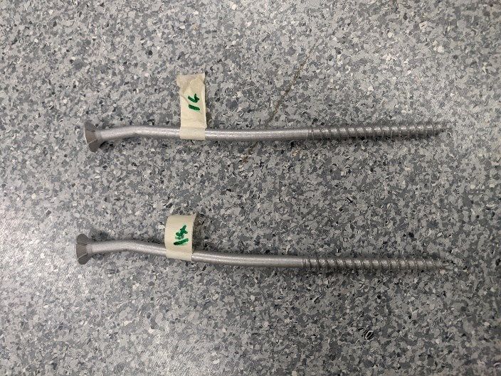
INTRODUCTION
Cross Laminated Timber (CLT) is an increasingly popular product used in the construction of large
timber structures. Being a panelised timber product CLT is primarily used for the construction of
timber wall and floor assemblies in large timber buildings.
In timber buildings that utilise CLT wall systems as their lateral load resisting system, the
connection properties play a key role in wall performance. As timber is primarily a brittle material
any ductility/yielding and energy dissipation in a timber system comes from the connections
between timber elements. It is therefore imperative that the performance of these connections
needs to be well understood.

Wall to foundation hold-down systems are critical when determining the lateral resistance of CLT
structures under wind or seismic loading. Previous research on CLT hold-down connections has
focused on connection systems such as off the shelf steel nail brackets, steel dowels, and
proprietary Holz-Stahl-Komposit (HSK) systems. These connection systems have been proven to
work well under seismic loading but have some limitations/concerns such as low capacity for off
the shelf steel nail brackets, strict installation tolerances for steel dowels, and quality control issues
for HSK systems that must be taken into account.

Large self-tapping screws are an increasingly common fastener type used in mass timber
construction. Easy to install on site by hand tools, these fasteners have allowed more efficient
connections than other dowel-type fasteners by exploiting the withdrawal capacity for increased
load carrying capacity (Blaß and Bejtka 2001). By increasing the angle of the screw we can
increase the connection stiffness, but with reduced ductility. Previous work (Tomasi et al. 2006)
investigated the suitability of mixed angle screw connections. In these connections both screws are
installed at both 45 degrees and 90 degrees to the grain, with the 45 degree screws acting
primarily in tension or withdrawal, and the 90 degree screws acting in shear. More work has
investigated their use in timber to timber in-plane joints between timber shear walls (Hossain,
Popovski, and Tannert 2018; Brown et al. 2020). Further work by Brown has investigated the
performance of these mixed angle screws as a hold-down system for a CLT core wall.

This study assesses the performance of mixed angle screw connections in steel to timber hold-
down joints. The influence of parameters such as screw thread length, washer choice, and ratio of
withdrawal to shear fasteners on key properties such as strength, stiffness, and ductility were
investigated under both monotonic and cyclic loading. These test results provide a first look into
the performance of these mixed angle screw installations in steel to timber connections, and
provide a good testing base for future design guidance for this type of connection.

                                                    2
                                                                            SWP-T119 Dfir CLT Report_G11.docx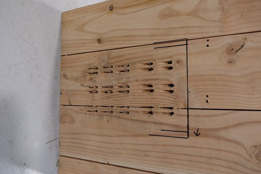
PHASE 1 TESTS: CONNECTIONS WITH 50-100 KN CAPACITY
Phase 1 tests aimed to conduct initial research to assess the performance of mixed angle screw
hold-down connections at a small scale. The hold-down specimens consisted of 2~6 fasteners and
the design load levels were between 50 and 100 kN. This small scale testing allowed for more
tests to study different parameters in a rapid fashion while keeping costs low.

The material used in all tests was Douglas-fir CLT provided by XLam New Zealand. The CLT used
a 175 mm thick 5 layer layup (45/20/45/20/45) with characteristic density of 470 kg/m3. Tests were
undertaken on a 250 kN Instron testing machine shown in Figure 1a. The test setup uses two steel
hold-downs at the base of the specimen in a symmetrical layout, and a dowelled overstrength
connection at the top of the connection as shown in Figure 1b.

                         a                                                  b
    Figure 1 – Phase 1 testing setup (a – Picture of testing setup, b – drawing of testing setup)

All tests were displacement controlled with monotonic tests undertaken in accordance with
EN12512 ‘Timber structures - Test methods - Cyclic testing of joints made with mechanical
fasteners’ (British Standards Institution 2001). Cyclic tests were undertaken in accordance with
ISO 16670 ‘Timber structures - Joints made with mechanical fasteners - Quasi-static reversed-
cyclic test method’ (International Organization for Standardization 2003). The rate of loading for
monotonic tests was 2 mm per minute, and 30 mm per minute for cyclic tests to meet EN12512
and ISO16670 respectively.

For all tests, the yield point was calculated using the procedure outlined in EN12512, where the
yield point is the intersection of a line through 0.1*Fmax and 0.4*Fmax and a tangent with 1/6th the
gradient. This method is shown graphically in Figure 2. Ultimate displacement was calculated as
failure or 0.8*Fmax deviating from EN12512’s 30 mm displacement limit. This was done as a 30 mm
displacement limit does not make sense when testing highly ductile connection systems that can
sustain peak load well past this limit.

                                                  3
                                                                         SWP-T119 Dfir CLT Report_G11.docx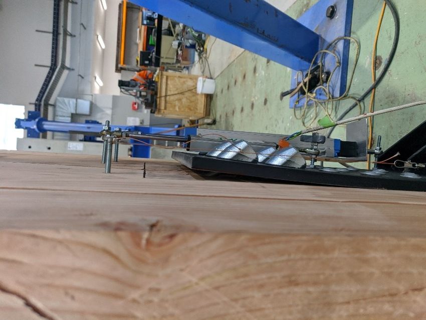
The cyclic loading protocol from ISO16770 was used. This protocol is defined as repeated cycles
to an increasing percent of ultimate displacement and is shown in Table 1 and Figure 3.

          Figure 2 – EN12512 definition of yield point (British Standards Institution 2001)

  Table 1 – Cyclic displacement protocol as defined by ISO16670 (International Organization for
                                     Standardization 2003)
             Step                         No. of cycles                Amplitude (% of Δu)
                             1                               1                             1.25
                             2                               1                               2.5
                             3                               1                                  5
                             4                               1                               7.5
                             5                               1                                10
                             6                               3                                20
                             7                               3                                40
                             8                               3                                60
                             9                               3                                80
                            10                               3                              100
                            11                               3                              120

  Figure 3 – Cycle displacement protocol as defined by ISO16670 (International Organization for
                                     Standardization 2003)

                                                  4
                                                                        SWP-T119 Dfir CLT Report_G11.docx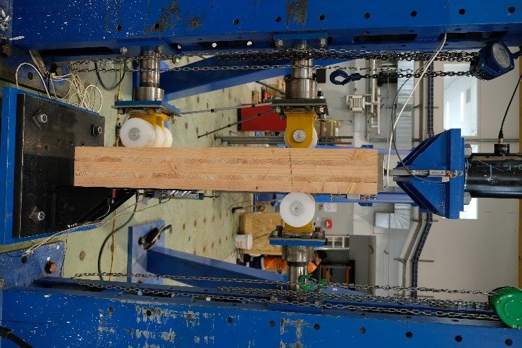
Test Program
 A total of 28 tests were undertaken to determine the following:
     1. Optimal threaded length of screw
     2. Suitability of 45 degree washers to this application
     3. Optimal ratio of withdrawal to shear fasteners

 The test matrix is shown in Table 2. The testing program began with tests with fasteners just in
 withdrawal or just in shear, followed by tests of partially threaded vs fully threaded inclined screws,
 and finally tests with both screws in withdrawal and screws in shear. Drawings of all the
 configurations tested are shown in Figure 4.

 The screws used in testing were all supplied by SPAX Pacific. All tests use 12 mm countersunk
 screws at 45 degrees and 10 mm washer head screws at 90 degrees. This is because SPAX does
 not manufacture a washer head screw larger than 10 mm diameter suitable for use in the shear
 connection.

                                 Table 2 – Test matrix for Phase 1
Test        Description            Withdrawal     Shear Screws         Ratio          Replicates
Set                                  Screws
                                  Qty     Size     Qty      Size                Monotonic        Cyclic
   1           2 Shear                                 2 10x180                         2             2
                                                               PT
   2        2 Withdrawal             2 12x260                                                3          3
                                             PT
   3     2 Withdrawal Fully          2 12x200          2 10x180                              1          1
             Threaded                        FT                PT
   4   2 Withdrawal 2 Shear          2 12x260          2 10x180           1:1                2          6
                                             PT                PT
   5   2 Withdrawal 2 Shear          2 12x200          2 12x180           1:1                1          3
          Fully Threaded                     FT                PT
   6   2 Withdrawal 4 Shear          2 12x200          4 12x180           1:2                1          3
                                             FT                PT

                                                    5
                                                                           SWP-T119 Dfir CLT Report_G11.docx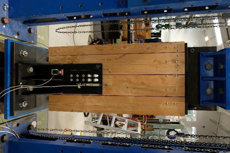
a                                                b

                      c                                               d

                     e                                                  f
 Figure 4 – Phase 1 test configurations. (a – 2 Shear, b – 2 Withdrawal, c – 2 Withdrawal Fully
Threaded, d – 2 Withdrawal 2 Shear, e – 2 Withdrawal 2 Shear Fully Threaded, f – 2 Withdrawal
                                            4 Shear)

                                              6
                                                                    SWP-T119 Dfir CLT Report_G11.docx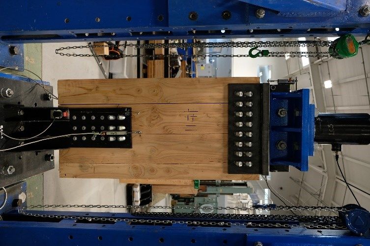
Results
Testing results for the 28 Phase 1 specimens are shown below in Table 3.

                                 Table 3 – Phase 1 test results
                        Fy      Fmax       Fu        K        Δy         ΔFmax         Δu          μ
                        kN       kN        kN       kN/m     mm            mm         mm
                                                     m
     1       2 Shear
 Monotonic       1       20.5     29.2      23.3     3.16          6.2      24.8        37.4       6.04
                 2       20.3     31.1      24.9     3.63         4.71      23.7        37.1       7.88
              Mean       20.4     30.1      24.1     3.39         5.46      24.3        37.3       6.96
   Cyclic        1       26.1      35        28      2.95         8.43      26.7        37.5       4.45
                 2       23.5     33.3      26.6     3.13         6.42      26.3        36.9       5.75
              Mean       24.8     34.1      27.3     3.04         7.43      26.5        37.2        5.1
    2.1      2 Withdrawal Un-welded
 Monotonic       1       33.7     43.6      34.9       37         0.83      3.46        9.14         11
                 2        51      53.8       43      9.56         5.25       7.7        12.4       2.36
              Mean       42.3     48.7      38.9     23.3         3.04      5.58        10.8       6.69
   Cyclic        1       57.1     61.6      49.3     21.5          2.5      4.01        8.39       3.36
                 2       55.8     61.1      48.9     19.2          3.5      5.64        8.99       2.57
                 3       49.4      52       41.6     8.53         5.41      7.54        11.3       2.09
              Mean       54.1     58.2      46.6     16.4          3.8      5.73        9.55       2.67
    2.2      2 Withdrawal
 Monotonic        1      56.5       63      50.4     21.4         3.31      5.55        10.9       3.29
     3       2 Withdrawal Fully Threaded
 Monotonic        1      73.8     77.6      62.1     26.6         3.18      4.32        9.14       2.87
  Cyclic          1      70.4     75.1      60.1     23.6         2.99      4.26        8.82       2.95
    4.1      2 Withdrawal 2 Shear Un-welded
 Monotonic       1       79.3     79.3      63.5     14.4         5.04       5.5        11.5       2.28
  Cyclic         1       88.5     96.4      77.1     27.9         3.72      6.71        11.8       3.17
                 2       80.3      82       65.6     17.8         4.27      4.88        11.8       2.77
                 3       77.2      78       62.4      17           4.5      5.52        11.7        2.6
              Mean        82      85.5      68.4     20.9         4.16       5.7        11.8       2.84
    4.2      2 Withdrawal 2 Shear
 Monotonic       1       66.3      73       58.4     24.2         2.47      4.86        13.7       5.52
  Cyclic         1       63.3     71.9      57.5     27.1         2.12      4.62         35        16.5
                 2       68.6      74       59.2     26.1         2.39      3.74         15        6.27
                 3       66.3     75.4      60.3      33           1.8      3.71        10.7       5.95
              Mean       66.1     73.8       59      28.7          2.1      4.02        20.2       9.56
     5       2 Withdrawal 2 Shear Fully Threaded
 Monotonic       1       92.4       99      79.2     32.2         2.62      4.27        7.52       2.87
  Cyclic         1       97.1      110      87.8     41.3         2.14       4.2        5.43       2.54
                 2       102       102      81.4     23.3            4      4.72        7.73       1.93
                 3       89.8       98      78.4     35.2         2.24      3.92        10.2       4.57
              Mean       96.2      103      82.5     33.3         2.79      4.28        7.79       3.01
     6       2 Withdrawal 4 Shear
 Monotonic       1       59.6      79       63.2      45          1.17      4.44         44        37.5
  Cyclic         1       78.1     94.3      75.5     33.8         1.94      29.5        39.9       20.6
                 2       78.1     97.2      77.8     43.6          1.6      28.9        35.5       22.2
                 3       78.7     99.1      79.2     43.1         1.66       7.5        38.4       23.2
              Mean       78.3     96.9      77.5     40.1         1.73        22        37.9        22

                                                7
                                                                         SWP-T119 Dfir CLT Report_G11.docx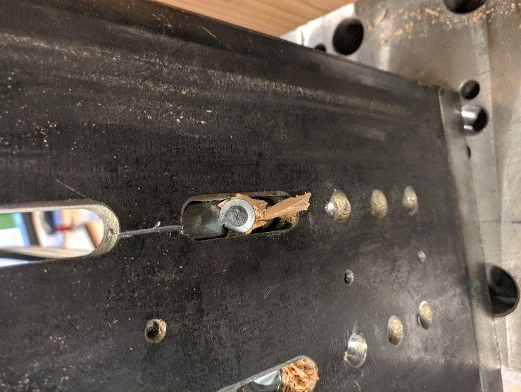
Discussion
Optimal threaded length of screw
In mixed angle screw connections it is important to size withdrawal screws such that they do not
fail prematurely in tension, but rather withdrawal from the timber in a less brittle failure mechanism.
As the performance of the joint is a combination of the performance of both the withdrawal screws
and the shear screws it is important that the withdrawal screws continue to maintain some load
carrying capacity as the shear screws take up the load at higher displacements. Otherwise an
abrupt transfer of load may result in a progressive failure mechanism being triggered.
Results from our previous testing showed that in Douglas-fir timber the screw embedment length
required to fail the screws in withdrawal is between 12d and 16d, or less. Tests were therefore
undertaken with both partially threaded screws (100 mm of threaded length) and fully threaded
screws (200 mm is the smallest length available). Accounting for the length of a 45 degree washer
and 12 mm plate a 200 mm fully threaded screw has a threaded embedment of 163 mm, which for
a 12 mm screw is 13.6d. During the 2 withdrawal test set, the fully threaded screws with 200 mm of
threaded length initially worked well with higher strength and stiffness than partially threaded
screws, while still maintaining similar displacement capacity as seen in Figure 8. However during
further testing in the 2 withdrawal 2 shear configuration it was found that the fully threaded screws
were prone to tensile failure at the screw to timber interface as shown in Figure 5. Figure 6 shows
a plot of the 2 withdrawal 2 shear test with fully threaded screws against the partially threaded
screws. Note the large drop in force in the fully threaded test due to the tensile failure of one of the
two withdrawal screws.

     Figure 5 – Example of fully threaded screw tensile failure at the timber to steel interface.

                                                   8
                                                                          SWP-T119 Dfir CLT Report_G11.docx
Figure 6 – Plot showing monotonic fully threaded vs partially threaded tests with 2 screws in
withdrawal 2 in shear.
Suitability of 45 degree washers to this application
45 degree washers from two manufactures were used and evaluated for this study. In phase 1
washers supplied by Wurth were used, and in phase 2 washers supplied by Rothoblaas were
used. These inclined washers are typically used for traditional steel to timber joints where only
inclined screws are used. These connections are typically designed to remain elastic or with limited
ductility. In the 2 withdrawal tests the yield displacement was determined to be around 3 mm. As a
consequence these washers were likely not envisioned to be taken to the high displacements
required in a mixed angle screw connection where the 45 degree screws are required to still
provide some load carrying capacity up to around 40 mm.
Tests with 2 withdrawal and 2 withdrawal 2 shear fasteners were initially undertaken with 45
degree inclined washers installed as per the manufacturer specifications. During the testing it was
found that at large displacements, the bending moment developed in the screw caused an action
that pushed the tip of the washer out of its slot, meaning the connection lost its ability to carry load
as seen in Figure 7a. This bending action in the screw is shown in Figure 7c, where it can be seen
that a plastic hinge has been developed near the head of the screw as the washer provides some
rotational restraints to the head. In cyclic tests there were also issues where the 45 degree screw
withdrew significantly from its original position and when unloaded the washer slipped down the
screw shank and out of its slotted hole as seen in Figure 7b. To address these issues, two tack
welds were added to the tip of each washer as seen in Figure 7d. These tack welds allowed a
small tensile force to be transferred between the tip of the washer and the hold-down while not
effecting the bearing of the tip of the washer against the end of the slotted hole. These tack welds
allowed the full development of the plastic hinge shown in Figure 7c, restraining the washer from
being able to slip out of place, thus allowing the screws in withdrawal to continue carry some load
well past their ultimate displacement.
In phase 2 the Rothoblaas washers used are designed for much thinner plates than the Wurth
washers used in phase 1, and as such, the plastic hinge developed about the edge of the slotted
hole rather than bearing into the washer.
Figure 8 shows a comparison for the 2 withdrawal tests between the welded and un-welded
washers. It can be seen that the un-welded washers reached failure at under 20 mm when the 45
degree washer slipped from its slot preventing any further load carrying by the screws in
withdrawal. In comparison the other two tests shown on Figure 8, both with welded washers, show
the ability of the welded washers to continue to provide some load carrying capacity right out to 40
mm of displacement.
9
SWP-T119 Dfir CLT Report_G11.docxa b
c d
Figure 7 – Pictures demonstrating 45 degree washers (a – 45 degree washer slipped from hole,
b – 45 degree washer unable to re-find hole under cyclic loading, c – withdrawal screws showing
two plastic hinges, d – 45 degree washer with two tack welds at the tip)
10
SWP-T119 Dfir CLT Report_G11.docxFigure 8 – Plot showing monotonic fully threaded vs partially threaded vs partially threaded un-
welded washers tests with 2 screws in withdrawal
Optimal Ratio of withdrawal to shear fasteners
Tests were conducted varying the ratio of withdrawal screws to shear screws between 1:1 and 1:2.
Due to constraints in the test setup for phase 1, intermediate ratios such as 1:1.5 could not be
investigated, and as such, they will be investigated in phase 2.
Figure 9 shows a plot of monotonic shear and withdrawal only tests against the tests with 1:1 ratio
and 1:2 ratio of withdrawal to shear fasteners. It can be seen that withdrawal fasteners have high
initial stiffness, but low ductility/displacement capacity, whereas shear fasteners have relatively low
initial stiffness and high ductility/displacement capacity. When these two types of fasteners are
combined into one connection, the behaviour could be superimposed with improved overall
performance , i.e., high initial stiffness and high ductility/displacement capacity.
Due to constraints discussed previously the withdrawal screws used were 12 mm diameter while
the shear screws were 10 mm diameters, therefore, any ratios provided are specific to this
combination of diameters. From Figure 9, it can be seen that both 2 withdrawal 2 shear and 2
withdrawal 4 shear curves have high initial stiffness, but the 2 withdrawal 2 shear curve drops
quickly at higher displacement indicating the need for more shear fasteners to sustain the loads.
The 2 withdrawal 4 shear curve with the two additional shear fasteners was able to sustain peak
load until a much larger displacement, and thus, leading to significantly higher
ductility/displacement capacity.
Cyclic performance of both 2 withdrawal 2 shear and 2 withdrawal 4 shear connections is shown in
Figure 10 and Figure 11 respectively. From Figure 10 it can be seen that the cyclic performance of
the 2 withdrawal 2 shear connection closely matches the monotonic performance. Similarly in
Figure 11 the cyclic performance of the 2 withdrawal 4 shear connection is comparable to the
monotonic connection, but is slightly stronger for most displacements, and perhaps, shows some
cyclic degradation at high displacements (40 mm +).
11
SWP-T119 Dfir CLT Report_G11.docxFigure 9 – Plot of monotonic shear and withdrawal only screws against 1:1 ratio and 1:2 ratio
tests
Figure 10 – Plot of 2 withdrawal 2 shear monotonic loading against cyclic loading
Figure 11 – Plot of 2 withdrawal 4 shear monotonic loading against cyclic loading
12
SWP-T119 Dfir CLT Report_G11.docxPHASE 2 TESTS: CONNECTIONS WITH 300-700 KN CAPACITY
Phase 2 aimed to build upon the findings of phase 1 tests and extend the findings at a larger scale
while optimising screw ratios, and testing possible post-earthquake repair solutions.
Tests undertaken in phase 2 evaluated connections with between 18 and 36 fasteners and load
levels between 300 and 700 kN. This larger scale tests provided results at a scale similar to what is
likely used in a multi-storey CLT building, proving the performance of these connection systems at
a more realistic scale.
Tests were undertaken on a steel loading frame using a 1000 kN hydraulic actuator. As shown in
Figure 12 and Figure 13 the testing setup features a mixed angle screw hold-down connection with
the base plate bolted to a steel foundation. Load is then applied to the specimen through a
screwed overstrength connection to the hydraulic actuator. Throughout testing the hold-downs and
arrangements were varied to provide different test cases.
The material used in all tests was Douglas-fir CLT provided by XLam New Zealand. The CLT used
a 175 mm thick 5 layer layup (45/20/45/20/45) with characteristic density of 470 kg/m3. The
specimens used in phase 2 had a width of 632.5 mm and height of 1265 mm.
Similar to phase 1, EN12512 test standard was used for monotonic tests, and ISO 16670 test
standard for cyclic tests. A target speed of 12 mm/min was chosen as this suited the capabilities of
the hydraulic actuators.
a b c
Figure 12 – Drawings of Phase 2 test setups (a – 8 withdrawal 12 shear, b – 6 withdrawal 12
shear singled sided, c – 12 withdrawal 24 shear)
13
SWP-T119 Dfir CLT Report_G11.docxa b c
Figure 13 - Pictures of Phase 2 test setups (a – 8 withdrawal 12 shear, b – 6 withdrawal 12
shear singled sided, c – 12 withdrawal 24 shear)
14
SWP-T119 Dfir CLT Report_G11.docxTest Program
A total of 27 tests were undertaken to determine the following:
• How the hold-downs performed in previous wall testing (SWP-T082).
• How the single sided performance of the hold-down compares to the double sided
performance.
• Optimal ratio of withdrawal to shear screws.
• How this connection system can be repaired post-earthquake event such that it regains
similar performance to new.
A test matrix of all unrepaired tests is shown in Table 4, and a test matrix of all repaired tests is
shown in Table 5. Drawings of all four testing configurations are shown in Figure 14. Repaired
tests all utilise a horizontal shift from the original position of half the screw spacing. As the screw
spacing used in the 12 withdrawal 24 shear hold-downs was 32.5 mm, the hold-downs were shifted
16.25 mm horizontally then reinstalled. This was achieved by moving the baseplate horizontally in
slotted holes while keeping the specimen in the same position.
Similar to Phase 1, screws used in testing were all supplied by SPAX Pacific. All tests use 12 mm
screws at 45 degrees and 10 mm screws at 90 degrees.
Table 4 – Test matrix for Phase 2 original tests
Test Description Single Withdrawal Shear Ratio Replicates
Set Sided Screws Screws
Qty Size Qty Size Monotonic Cyclic
1 8 Withdrawal 12 No 8 12x160 12 10x180 1:1.5 1 3
Shear PT PT
2 6 Withdrawal 12 Yes 6 12x260 12 10x180 1:2 2 3
Shear Single PT PT
Sided
3 12 Withdrawal 24 No 12 12x260 24 10x180 1:2 1 3
Shear PT PT
6 12 Withdrawal 18 No 12 12x260 18 10x180 1:1.5 2 3
Shear PT PT
Table 5 – Test matrix for Phase 2 repaired tests
Test Description Repair Withdrawal Shear Screws Ratio Replicates
Set Screws
Qty Size Qty Size Monotonic Cyclic
4 12 Withdrawal Hilti + Shift 12 12x260 24 10x180 1:2 1 3
24 Shear PT PT
Repaired
5 12 Withdrawal Shift 12 12x260 18 10x180 1:1.5 2 3
18 Shear PT PT
Repaired
15
SWP-T119 Dfir CLT Report_G11.docxa b
c d
Figure 14 – Phase two test configurations (a – 8 Withdrawal 12 Shear, b – 6 Withdrawal 12
Shear Single Sided, c – 12 Withdrawal 24 Shear, d – 12 Withdrawal 18 Shear)
16
SWP-T119 Dfir CLT Report_G11.docxResults
Testing results for the 27 phase 2 specimens are shown below in Table 6.
Table 6 – Phase two test results
Fy Fmax Fu K Δy ΔFmax Δu μ
kN kN kN kN/mm mm mm mm
1 8 Withdrawal 12 Shear
Monotonic 1 250 322 258 114 1.94 27.4 39 20.1
Cyclic 1 295 363 290 107 2.55 30.7 39.6 15.5
2 359 391 312 116 2.9 4.88 36.1 12.4
3 290 341 273 134 1.89 4.95 36.8 19.5
Mean 315 365 292 119 2.45 13.5 37.5 15.8
2 6 Withdrawal 12 Shear Single Sided
Monotonic 1 331 372 297 149 2.03 5.46 23.8 11.7
2 251 314 251 135 1.59 18.9 24 15.1
Mean 291 343 274 142 1.81 12.2 23.9 13.4
Cyclic 1 316 372 298 151 1.85 21.1 26.4 14.3
2 314 342 274 123 2.32 17.2 22.7 9.8
3 276 328 262 150 1.67 16.9 23.2 13.9
Mean 302 347 278 141 1.94 18.4 24.1 12.7
3 12 Withdrawal 24 Shear
Monotonic 1 522 643 515 216 2.04 30.6 39.5 19.3
Cyclic 1 504 622 498 222 2.01 36 40.6 20.2
2 498 609 487 238 1.81 31.2 39.6 21.8
3 544 633 506 223 2.04 31.8 40.3 19.7
Mean 515 621 497 228 1.96 33 40.2 20.6
4 12 Withdrawal 24 Shear Repaired with Hilti Epoxy + Shift
Monotonic 1 555 653 522 195 2.56 30.2 38.9 15.2
Cyclic 1 559 658 527 229 2.12 6.05 38.9 18.4
2 556 621 497 187 2.76 7.5 37.7 13.6
3 587 692 554 240 2.11 33.1 40.1 19
Mean 567 657 526 219 2.33 15.6 38.9 17
5 12 Withdrawal 18 Shear
Monotonic 1 433 546 437 286 1.37 6.25 36.5 26.7
2 423 535 428 295 1.19 7.06 39.2 32.9
Mean 428 540 432 290 1.28 6.65 37.8 29.8
Cyclic 1 521 614 491 294 1.54 4.61 40.5 26.2
2 487 590 472 271 1.47 5.43 35.9 24.4
3 447 535 428 270 1.42 4.16 37.6 26.5
Mean 485 580 464 278 1.48 4.73 38 25.7
6 12 Withdrawal 18 Shear Repaired With Shift
Monotonic 1 453 509 407 185 1.92 4.54 35.9 18.7
2 362 489 391 224 1.3 29.2 38.4 29.6
Mean 408 499 399 204 1.61 16.8 37.1 24.1
Cyclic 1 407 542 433 294 1.97 31.2 40.6 20.7
2 426 516 413 223 1.72 32.6 39.1 22.7
3 355 447 357 265 1.11 3.97 36.3 32.6
Mean 396 501 401 261 1.6 22.6 38.7 25.3
17
SWP-T119 Dfir CLT Report_G11.docxDiscussion
Hold-down component test for previous wall testing
Previous wall testing (SWP-T082) used mixed angle screw hold-downs on the base of a 2/3rd scale
4-storey CLT core wall. This hold-down test set was an exact replica of the hold-down setup used
on the wall tests and provided a calibration for hold-down forces in future modelling work.
For this test hold-downs with reduced spacing (20 mm horizontally) are used with shorter 12x160
mm partially threaded countersunk screws. The same 10x180 mm washer head screws were used
in shear.
Figure 15 shows a plot of monotonic vs cyclic behaviour for this connection. It can be seen that in
this case the monotonic test was weaker than the cyclic test, although this is likely due to variability
in the timber rather than a significant trend. It should be noted that for the 1:1.5 withdrawal to shear
ratio in these tests we observed a slightly lower initial peak and slightly higher second peak which
was not the case in later tests with 1:1.5 ratio. It was likely that in this case either the length of
screw or spacing was contributing to slightly lower withdrawal strength than compared to other
similar tests with higher spacing and longer screws. Further work is required to address this cause
separately.
Figure 15 – Plot of 8 withdrawal 12 shear monotonic vs cyclic
Single sided vs double sided
Figure 19 shows a monotonic comparison between the recorded strength of the 6 withdrawal 12
shear single sided hold-down and half the recorded strength of the 12 withdrawal 24 shear double
sided hold-down test. Similarly Figure 20 shows a cyclic comparison between these two test sets.
From Figure 19 and Figure 20 it is apparent that the single sided hold-down test had higher
strength than the equivalent double sided hold-down test. This difference might be caused by the
different frictional effect between the two tests. In a double sided hold-down test the timber
specimen fits snugly between the hold-downs, and the base is constrained from sliding inwards.
When the fasteners engage and try to pull the hold-downs inwards, stiffeners prevent the base of
the hold-down from bending inwards to contact the timber surface, although the top of the hold-
down is free to bend in. In the single sided test there is only a connection on one side of the timber
so the horizontal component of the fasteners resistance across the steel timber interface is
unbalanced as such the hold-down is allowed to sit firm against the single sided hold-down
generating more frictional resistance.
It is also apparent from Figure 19 and Figure 20 that the single sided hold-down has significantly
less ductility/displacement capacity than the double sided hold-down. This was likely due to the
horizontal constraint present in the double sided hold-down test. At high displacements the inclined
18
SWP-T119 Dfir CLT Report_G11.docxscrews in the connection seek to push the hold-down away from the timber specimen as shown in
Figure 18a. In the double sided hold-down test this action is well constrained by the opposing hold-
down. In the single sided test this action is only constrained by a roller support only tightened until
snug. In some tests this allowed a small gap to form between the hold-down and the timber surface
significantly reducing the load carrying capacity of the joint. An accentuated version of this is seen
in Figure 18b when the roller support has not been tightened sufficiently and the timber has been
allowed to push away from the hold-down.
Figure 16 – Plot of 6 withdrawal 12 shear vs 12 withdrawal 24 shear monotonic halved for
comparison
Figure 17 - Plot of 6 withdrawal 12 shear vs 12 withdrawal 24 shear cyclic halved for comparison
19
SWP-T119 Dfir CLT Report_G11.docxa b
Figure 18 – Photos of the hold-down being forced away from the timber specimen by the inclined
screws at high displacements (a – Hold-down being forced away but being held snug against the
hold-down by 90 degree screws, b – Hold-down being forced away from the timber specimen)
Optimal ratio of withdrawal to shear screws
From Phase 1 testing it was concluded that a 1:2 ratio of withdrawal to shear screws performed
better than a 1:1 ratio. In the larger scale tests of Phase 2 it was possible to test both 1:2 and 1:1.5
ratio to find a more optimal solution. Figure 19 shows a monotonic comparison between 12
withdrawal 24 shear (1:2 ratio) and 12 withdrawal 18 shear (1:1.5 ratio). Similarly, Figure 20 shows
a cyclic comparison between 12 withdrawal 24 shear and 12 withdrawal 18 shear. In both Figure
19 and Figure 20 it can be seen that 1:2 provided slightly higher yield strength and was much
stronger at high displacements. This is intuitive as the extra shear screws will provide less capacity
at lower displacements and more capacity at higher displacements. Based on the tabulated values
in Table 6 it can be seen that for cyclic tests 1:1.5 ratio achieved a higher ductility ratio (25.7 to
20.6). On further investigation it can be determined that this is actually due to a slightly lower yield
strength due to the way it is calculated using EN12512. Discarding this, it can be seen that 1:2 ratio
has a higher mean ultimate displacement (40.2 mm vs 38 mm) therefore meaning that the 1:2 ratio
has a higher displacement capacity.
Dividing average cyclic max load through by the number of fasteners it can be seen that 1:1.5 has
a slightly higher force per fastener than 1:2 (19.33 kN/fastener vs 17.25 kN/fastener).
As the load drops away at high displacement with 1:1.5 ratio it is recommended that 1:2 is used as
this has more favourable performance at high displacements.
20
SWP-T119 Dfir CLT Report_G11.docxFigure 19 – Plot of 12 withdrawal 24 shear vs 12 withdrawal 18 shear monotonic
Figure 20 – Plot of 12 withdrawal 24 shear vs 12 withdrawal 18 shear cyclic
Repairs
Large self-tapping screw assemblies have a key advantage compared to other connection systems
such as dowels or HSK in that they can be installed into the face of CLT walls when the CLT wall is
already in place. Taking this ease of assembly advantage a step further, it is possible to install
these connections after the CLT building is completed and in service as a repair for existing
connections. Looking at the damage sustained in the previous tests that were taken to ultimate
load, it can be seen that the damage was localised and concentrated around the screw hole. It was
therefore possible to repair this connection type by shifting the connection horizontally by half
spacing and installing new fasteners into the same steel hold-down bracket.
Two repair solutions were investigated. The first used Hilti HIT-RE 500 v3 epoxy injected into
damaged holes to repair the damaged timber, then shifting the connection horizontally by half
spacing. The second left the damaged holes untouched and simply implement the half spacing
shift with no repair to the damaged timber. Pictures of the Hilti + shift and shift only connections are
shown in Figure 25a and Figure 25b respectively.
21
SWP-T119 Dfir CLT Report_G11.docxFrom Figure 21 and Figure 22 it can be seen that under both monotonic and cyclic loading the
connection repaired with Hilti epoxy + a horizontal shift has higher peak load, but slightly reduced
displacement capacity. This is likely due to the high strength Hilti epoxy filling gaps and voids in the
timber, providing extra resistance for screws in withdrawal. The same increase in strength is not
seen at large displacements suggesting that the Hilti epoxy only affects the withdrawal resistance
and not the shear resistance. This makes sense as at the surface of the timber, the shear
fasteners are bearing into fresh undamaged timber with no Hilti epoxy.
From Figure 23 and Figure 24 it can be seen that under both monotonic and cyclic loading the
connection repaired by just a horizontal shift has consistently lower strength than the original
undamaged connection throughout all displacements. It should be noted that although there is a
drop in strength, this drop is small compared to the magnitude of the load.
These tests prove the suitability of mixed angle screw hold-down connections to repair and present
two viable methods, one achieving greater load than un-repaired, the other slightly lower, but both
having broadly similar behaviour to the original connection.
Figure 21 – Plot of monotonic 12 withdrawal 24 shear original vs repaired with Hilti + shift
Figure 22 - Plot of cyclic 12 withdrawal 24 shear original vs repaired with Hilti + shift
22
SWP-T119 Dfir CLT Report_G11.docxFigure 23 - Plot of monotonic 12 withdrawal 18 shear original vs repaired with shift only
Figure 24 - Plot of cyclic 12 withdrawal 18 shear original vs repaired with shift only
23
SWP-T119 Dfir CLT Report_G11.docxa b
Figure 25 – Photo of repaired connections after being tested twice (a – Hilti + shift, b - shift)
24
SWP-T119 Dfir CLT Report_G11.docxCONCLUSION
The experimental project confirmed the suitability of Douglas-fir CLT and mixed angle screw
installations for high capacity hold-down systems. These connection results will provide valuable
technical information for engineers to design mass timber structures utilising Douglas-fir CLT in the
lateral load resisting system to resist seismic loads.
Main findings from Phase 1 small scale tests are listed as follows:
• Optimal threaded length of screw
From these tests it can be seen that although fully threaded screws can provide higher stiffness
and more load carrying capacity per fastener, tensile failure of the screw must be avoided to allow
their use in this style of connection. Shorter fully threaded screws are available from other
suppliers, but by reducing their length to avoid tensile failure, the benefits of fully threaded screws
over partially threaded screws may be reduced.
• Suitability of 45 degree washers to this application
Both the Wurth and Rothoblaas washers evaluated are suitable for mixed angle screw connection
type as long as proper detailing allows for the formation of a plastic hinge at the head of the
withdrawal screw. For the Wurth washer used in phase 1 this required the addition of two tack
welds at the tip of the washer, but with significantly thicker plate this would not be required.
Similarly the Rothoblaas washers tested did not require any tacks welds when used with the 12
mm thick plate but would require tack welds for the 8 mm thick plate or thinner.
• Optimal Ratio of withdrawal to shear fasteners
Using a combination of fasteners in withdrawal and fasteners in shear both high initial stiffness and
high ductility/displacement capacity can be achieved. With the configuration tested (12 mm screws
in withdrawal, 10 mm screws in shear), the ratio of 1:2 was found to perform better than a ratio of
1:1. Further testing in phase 2 will work to investigate the ratio of 1:1.5 as this may be more
efficient than 1:2. During testing it was found that this connection type performs well under both
monotonic and cyclic loading, with some cyclic degradation being seen at very high displacements.
It is worth mentioning though that the cyclic protocol used from ISO 16670 is a very demanding
testing protocol compared to what a timber building is likely to experience in an earthquake event.
Main findings from Phase 1 small scale tests are listed as follows:
• Component test for hold-downs used in previous wall testing
The hold-downs used in previous wall testing had high initial stiffness and significant
ductility/displacement capacity as would be expected for a mixed angle screw hold-down. This data
showed that the hold-downs installed in the wall tests performed well, and provided calibration data
for future numerical simulations of the wall system.
• Single sided vs double sided
Testing showed that the horizontal constraints imposed by a double sided hold-down test provided
significant displacement capacity performance benefits over a single sided test that was not well
horizontally constrained. The impact of these constraints provided implications for how these hold-
downs are used in future CLT structures. Although the wall is likely constrained horizontally out of
plane by other connections and fasteners, the significant performance reduction should be noted
and further research in this area is required.
25
SWP-T119 Dfir CLT Report_G11.docx• Optimal ratio of withdrawal to shear screws
The 1:1.5 ratio of withdrawal to shear screws was found to have higher load carrying capacity per
fastener and therefore be more efficient. However, it should be noted that at high displacement the
load sustained was less than the peak (although more than 80%) and therefore, it is recommended
that the 1:2 ratio be used as this has more favourable performance at high displacements.
• Repairs
Of the two repair strategies tested it was found that both performed well under both monotonic and
cyclic loads, although displacement capacity was slightly reduced. This proved the suitability of
mixed angle screw hold-down connections to repair. Of the two repair methods presented it is
recommended to use the Hilti + shift method.
26
SWP-T119 Dfir CLT Report_G11.docxACKNOWLEDGEMENTS
The authors would like to thank University of Canterbury technicians Mr. Gavin Keats and Mr. Alan
Poynter, for their valuable input and support throughout the test programme.
Additional support provided by Spax Pacific Ltd and XLAM Ltd is greatly appreciated for supplying
the fasteners and CLT materials.
REFERENCES
Blaß, Hans Joachim, and Ireneusz Bejtka. 2001. “Screws with Continuous Threads in Timber
Connections.” In In: Joints in Timber Structures. Proceedings of the International RILEM
Symposium, Stuttgart, Germany 2001. Ed.: S. Aicher, 22:193–201. RILEM-Publ., Cachan.
British Standards Institution. 2001. “BS EN 12512:2001: Timber Structures. Test Methods. Cyclic
Testing of Joints Made with Mechanical Fasteners,”
Brown, Justin R., Minghao Li, Thomas Tannert, and Daniel Moroder. 2020. “Experimental Study on
Orthogonal Joints in Cross-Laminated Timber with Self-Tapping Screws Installed with
Mixed Angles.” Engineering Structures, December, 111560.
https://doi.org/10.1016/j.engstruct.2020.111560.
Hossain, Afrin, Marjan Popovski, and Thomas Tannert. 2018. “Cross-Laminated Timber
Connections Assembled with a Combination of Screws in Withdrawal and Screws in
Shear.” Engineering Structures 168 (August): 1–11.
https://doi.org/10.1016/j.engstruct.2018.04.052.
International Organization for Standardization. 2003. “Timber Structures - Joints Made with
Mechanical Fasteners - Quasi-Static Reversed-Cyclic Test Method (ISO 16670:2003).”
Tomasi, Roberto, Maurizio Piazza, Albino Angeli, and Mario Mores. 2006. “A New Ductile
Approach Design of Joints Assembled with Screw Connectors,” August, 6.
27
SWP-T119 Dfir CLT Report_G11.docxYou can also read