Repair of a Cracked Historic Maryan Bell by Gas Welding - MDPI
←
→
Page content transcription
If your browser does not render page correctly, please read the page content below
materials
Article
Repair of a Cracked Historic Maryan Bell by Gas Welding
Dariusz Bartocha              and Czesław Baron *

                                          Department of Foundry, Silesian University of Technology, 7 Towarowa St., 44-100 Gliwice, Poland;
                                          dariusz.bartocha@polsl.pl
                                          * Correspondence: czeslaw.baron@polsl.pl

                                          Abstract: In this article, the range of works connected with the repair of a historical Maryan bell from
                                          1639 are presented. The first attempts to repair damaged bells occurred in the 1930s in Poland. How-
                                          ever, this process was stopped because of extensive technological difficulties. Welding and soldering-
                                          welding were the basic methods. There is one difference between these two methods—connecting
                                          surfaces are melted during the welding process but only heated until the melting temperature of the
                                          material added to the connection (that is the solder) during the soldering-welding process. It was
                                          important to heat the bell to the proper temperature during welding. Uneven heating causes the
                                          enlargement of existing cracks or the appearance of new ones, or even the complete destruction of the
                                          bell. Nowadays, a method of even heating using a special heating mat has been devised. Thanks to
                                          this method it is possible to control the heating and cooling process. The most important task during
                                          the whole operation of bell welding was obtaining the original sound. During this research, the
                                          chemical composition was examined to prepare a welding rod with a suitable chemical composition.
                                          After the repair process, an analysis of the sound of the bell was conducted. It was shown that the
                                          repair of bells is possible when correct thermal parameters are used. The most highly recommended
                                          technique for repairing bells is gas welding.

                                   Keywords: high-tin bronzes; microstructure; welding of bell; bell’s sound
Citation: Bartocha, D.; Baron, C.
Repair of a Cracked Historic Maryan
Bell by Gas Welding. Materials 2021,
14, 2504. https://doi.org/10.3390/        1. Introduction
ma14102504
                                                There are a lot of churches with very old, historical bells in Poland, as it has historically
                                          been a Catholic country. Unfortunately, their strength is decreasing and cracks and scratches
Academic Editor: Sergei Yu Tarasov
                                          are have appeared. These defects make them useless, because not only does the sound
                                          become worse, but reacting to the damage too late can cause the complete destruction of
Received: 2 April 2021
                                          the bell as well.
Accepted: 9 May 2021
Published: 12 May 2021
                                                The lifetime of the bell was determined to be 200–300 years [1] on the basis of data in
                                          the literature. After that time the probability of the bell cracking is increased. Of course,
Publisher’s Note: MDPI stays neutral
                                          it depends on many factors, such as the frequency of bell work and the bell’s rotation on
with regard to jurisdictional claims in
                                          its suspension. Unless the bell is rotated, the clapper hits the same place and it may cause
published maps and institutional affil-
                                          cracks. It is important to control the thickness of that place. If the thickness falls more than
iations.                                  10%, it is necessary to rotate the bell to allow it to hit another place. Constant hits on the
                                          same place also causes changes to the inner structure of the material. It becomes harder
                                          and loses strength properties. Concurrently, inner stresses increase. When stresses exceed
                                          the material strength limit, the bell will be damaged, and cracks and scratches will appear.
                                          It is hard to notice such a crack on a bell placed high in a tower, but it is possible to hear
Copyright: © 2021 by the authors.
Licensee MDPI, Basel, Switzerland.
                                          the change in the sound, which is usually much worse than the original sound.
This article is an open access article
                                                The repair of the bell is possible up to its complete destruction. Repairing the bell is
distributed under the terms and
                                          an expensive and time-consuming process. However, attempts to repair these bells are not
conditions of the Creative Commons        rare, because the bell is a precious item not only thanks to its material value but also its
Attribution (CC BY) license (https://     historical and artistic value as well. Despite the avoidance of the repair of cracked bells in
creativecommons.org/licenses/by/          Poland for a long time, this problem has been considered in many other countries [2,3].
4.0/).

Materials 2021, 14, 2504. https://doi.org/10.3390/ma14102504                                               https://www.mdpi.com/journal/materials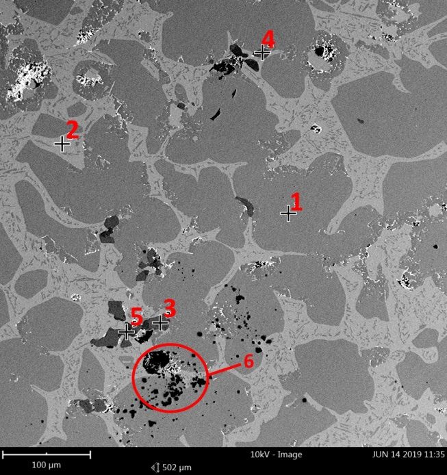
Materials 2021, 14, x FOR PEER REVIEW 2 of 10
Materials 2021, 14, 2504 2 of 10
It is necessary to examine the chemical composition of the alloy used to produce the
It is
bell to necessary
repair the crack. to examine thebells
The oldest chemical
are madecomposition
of gunmetal,of the alloy
while theused to produce
younger are made the
bell to repair
of bronze. the crack.
Copper at a The oldest bellsofare
concentration made
about 80%of and
gunmetal,
tin with while the younger between
a concentration are made
of bronze. Copper at a concentration of about 80% and
19% and 21% are the main components in both alloys. Gunmetal also contains zinc,tin with a concentration between
lead,
19% and 21% are the main components in both alloys. Gunmetal
carbon, and iron. Trace amounts of silver and gold are also possible to observe in both also contains zinc, lead,
carbon, and iron. Trace amounts of silver and gold are also possible
alloys because of the tradition to add these elements into the liquid metal to ennoble the to observe in both
alloys
material because
[4–6]. of the tradition to add these elements into the liquid metal to ennoble the
material [4–6].
The melting temperature of bronze is about 850–950 °C. The alloys with high tin con-
◦ C. The alloys with high tin
tent The melting temperature
are characterized by great of bronzebut
strength, is about 850–950low
concurrently toughness—they are very
content are characterized
brittle (Figure 1). This, in by great strength,
combination withbuthigh concurrently low toughness—they
thermal expansion and high diversityare very
of
brittle (Figure 1). This, in combination with high thermal expansion
the microstructure component properties, has a negative influence on weldability. It is and high diversity
of the microstructure
proper to heat the whole component
bell at theproperties,
adequatehas a negative
speed influence
until it reaches theontemperature
weldability.ofIt
is350–450
proper°C, to heat
before welding. This allows differences in temperature between the weldedof
the whole bell at the adequate speed until it reaches the temperature
350–450 ◦ C, before welding. This allows differences in temperature between the welded
place and the rest of the bell which are too large to be avoided. What’s more, it is also
place and the
important restitofslowly
to cool the bell
andwhich
evenly are toospeed
(the largeoftothe
becooling
avoided. What’s
process more,
should beitslower
is also
important to cool it slowly and evenly (the speed of the cooling process
than heating). This is connected with the risk of inducing residual heat as a result of dif- should be slower
than heating).
ferences This is rates
in the cooling connected with parts
of different the risk of structure
of the inducing(Figure
residual heat
2a,b as adifferent
shows result of
differences
phases accordingin the cooling rates ofcooling
to different different partsIfofthe
rates). the bell
structure (Figure
had not been2a,b showsonly
heated, different
the
phases
welded part would have shrunk and new cracks would have appeared. On thewelded
according to different cooling rates). If the bell had not been heated, only the other
part
hand,would have process
a cooling shrunk and new
which iscracks
too fast would have appeared.
may cause new stresses,On the
withother
newhand,
cracksa cooling
as the
process
result. which is too fast may cause new stresses, with new cracks as the result.
Figure
Figure 1. Theinfluence
1. The influenceofoftin
tinonon chosen
chosen mechanical
mechanical properties,
properties, the the tin bronze
tin bronze hardness
hardness change
change
dependent on tin
dependent tin concentration.
concentration.(E—elongation, UTS—ultimate
(E—elongation, UTS—ultimate tensile strength,
tensile BHN—Brinell
strength, BHN—Brinell
hardness number,
hardness number,KV—impact
KV—impact strength,
strength, YS—yield
YS—yield strength) [7].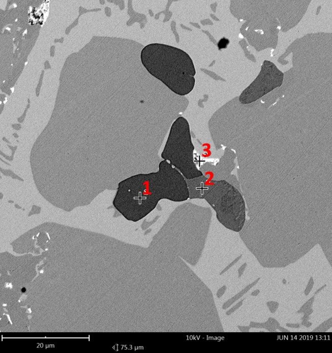
Materials 2021, 14,
Materials 2021, 14, 2504
x FOR PEER REVIEW 33 of
of 10
10
2. (a) Phase
Figure 2. Phase diagram
diagram Cu-Sn,
Cu-Sn, (b)
(b) Metastable
Metastable phases
phases Cu-Sn;
Cu-Sn; dashed
dashed line—casting
line—casting solidified in sandy mold, dotted
line—casting solidified
solidified in
in aa metal
metal mold
mold [8,9].
[8,9].
2. Historical
Historical Background
In Poland,
In Poland,the the first
first attempts
attempts to repair
to repair damaged damaged bells
bells were were observed
observed in the 1930s.in the 1930s.
Welding
Welding and soldering-welding were the base methods. There
and soldering-welding were the base methods. There is one difference between these two is one difference between
these two methods:
methods: connecting connecting
surfaces aresurfaces
melted areduring
melted welding
during welding
processprocess
and only andheated
only heated
until
untilmelting
the the melting temperature
temperature of the
of the material
material added
added to to the
the connection(that
connection (thatisissolder)
solder) during
the soldering-welding process. Additionally, a welding rod with a chemical composition
similar to
similar to indigenous
indigenous metal metal was
was used
used during
during welding
welding process,
process, whilst
whilst sticks
sticks made
made of of brass
brass
alloy (known as bronzite) were used for soldering-welding.
alloy (known as bronzite) were used for soldering-welding.
First, it
First, it was
wasdesirable
desirabletotoestimate
estimate thethesize of the
size crack.
of the A simple
crack. A simplepenetration
penetrationstudy was
study
conducted with the use of chalk and kerosene. Chalk was rubbed
was conducted with the use of chalk and kerosene. Chalk was rubbed into the inner side into the inner side of the
bellthe
of and theand
bell external side was
the external lubricated
side with kerosene.
was lubricated The greasy
with kerosene. Thespot
greasywasspotusedwas
to show
used
the range of the crack. After estimating the size of the damage, the
to show the range of the crack. After estimating the size of the damage, the place of repairplace of repair should
be properly
should prepared.
be properly In bothIn
prepared. cases,
boththe method
cases, of action
the method of was
actionsimilar. A groove
was similar. with a
A groove
v–shape was cut along the crack and metal was poured in. In
with a v–shape was cut along the crack and metal was poured in. In this procedure this procedure the hole at the
the
end of the crack must be remembered. Its task was to limit the increase
hole at the end of the crack must be remembered. Its task was to limit the increase of the of the crack during
bell heating.
crack duringAn bellacetylene
heating. torch was usedtorch
An acetylene as the welding
was used as tooltheinwelding
both methods.
tool in Uniformity
both meth-
of the weld obtained was the main difference between welding
ods. Uniformity of the weld obtained was the main difference between welding and the and the soldering-welding
process. The weld had nearly the same chemical composition as welded material during
soldering-welding process. The weld had nearly the same chemical composition as
the welding process. The weld had different chemical composition to the repaired bell
welded material during the welding process. The weld had different chemical composi-
during the soldering-welding process, which caused worse sound.
tion to the repaired bell during the soldering-welding process, which caused worse sound.
The position heated by charcoal (in the past it was often used as a fuel) was used
The position heated by charcoal (in the past it was often used as a fuel) was used to
to heat the bell before repair. This solution was connected with uneven bell heating and
heat the bell before repair. This solution was connected with uneven bell heating and cool-
cooling. It may have caused new cracks or increased the old ones as a result.
ing. It may have caused new cracks or increased the old ones as a result.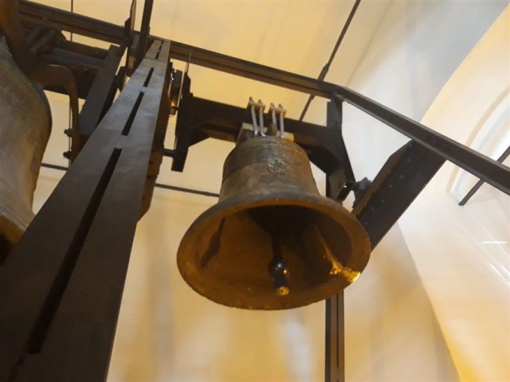
Materials 2021, 14, 2504 4 of 10
3. Maryan Bell Crack Repairing
The company Rduch Bells & Clocks and Foundry Department collectively made a
decision to repair a cracked Maryan bell from the 17th century at the request of urban
restorer in Krosno–Marta Rymar. The bell hangs in a church tower. It is the smallest bell of
three cast in 1639, weighing 580 kg. It is characterized by producing a “G#” sound. The bell
was cast by two bell founders, Szepan Meutel and Jerzy Olivier, for a special order from
the great philanthropist Robert Wojciech Portius. The Maryan bell is one of three treated
bells. On the tower there are also the Urban bell and the Jan bell. The bells are tuned to a
major scale. This means that they sound happy, merry, and concurrently noble. The lack of
one bell or unclear sound will cause the whole set to lose its musical value. This is why it
was so important not only to repair the crack but to do it in such a way as to avoid changes
to the sound.
The most important task during welding process was to obtain the original sound.
Fortunately, in 2013, during the change of the clapper, acoustic measurements were con-
ducted. Thanks to this it was possible to obtain the sound before and after the damage
to the bell (the damage occurred in 2017—exact date is unknown). This was the base for
further activities. The work was divided into a few steps:
1. The first step was to take a material sample to determine the averaged chemical
composition of the alloy, which was analyzed with a glow–discharge spectrometer
LECO GDS500A (LECO Corporation, St. Joseph, MI, USA, 2011) (Table 1);
2. In the next step a series of welding rods with the same chemical composition were
prepared on the basis of these results, which were used during bell welding process;
3. The next step was to determine the size and range of the crack, and penetration
research was conducted;
4. The next step was preparing the bell for the welding process by properly bevelling
the sides of the bell;
5. The next step was heating and keeping the bell at the proper temperature;
6. The next step was obtaining the required temperature to conduct welding process;
7. After welding slow cooling was conducted to avoid stresses;
8. The last step was analysis of the sound of the repaired bell.
Table 1. Chemical composition of the Maryan bell (wt. %).
Sn Pb Sb Zn Fe Ni Ag Cu
15.2 2.84 2.69 0.35 0.03 0.41 0.15 bal.
Accuracy in all of these activities allowed us to obtain the ideal sound from the repaired
bell. The samples of material obtained were examined with the use of a spectrometer to
determine averaged chemical composition (presented in Table 1). The analysis of structure
was also conducted with the use of a scanning microscope to determine the distribution and
size of solid and gaseous inclusions. (Figure 3a,b). The chemical composition in particular
places (with visible solid and gaseous inclusions) was presented in Table 2.
Metallographic microsections showed the original structure of the bell. Unfortunately,
many gaseous (Figure 3a, 6) and non–metallic inclusions were observed. A large amount
of carbon (Figure 3b, 1) can indicate residue of charcoal, which was used as fuel during
the melting process. Zinc inclusions were also observed (Figure 3a, 5).This negatively
influenced the welding process.
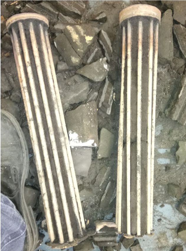
A series of welding rods were made after chemical composition determination and
consultations with the company conducting the welding process. Their composition was
selected to be as compatible as possible with the examined material of the bell. A set of
molds was worked out and prepared in the Foundry Department, and thanks to them
welding rods of different lengths and diameters were produced (Figure 4).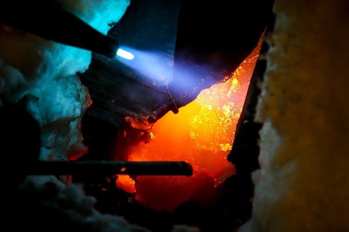
Materials 2021, 14, x FOR PEER REVIEW 5 of 10
Materials 2021, 14, 2504 5 of 10
(a) 100 μm (b) 20 μm
Figure
Figure 3. Location
3. Location of the
of the measurement
measurement points
points for for scanning
scanning microscope
microscope examination
examination withwith visible
visible impurities
impurities andand inclusions.
inclusions.
(a) 1–6
(a) 1–6 measurement
measurement points
points for magnification
for magnification 530× 530×,
, (b) (b)
1–31–3 measurement
measurement points
points for for magnification
magnification 800×.
800× .
Table
Table 2. Chemical
2. Chemical composition
composition in particular
in particular examined
examined places
places presented
presented in Figure
in Figure 3. 3.
Figure
Figure 3a 3a Figure
Figure 3b 3b
Element
Element Atomic
Atomic Element
Element Atomic
Atomic
Number
Number Number
Symbol Concentration Number Symbol Concentration
Symbol Concentration Symbol Concentration
Cu 21.43 C 75.57
Cu 21.43 C 75.57
C
C 70.37
70.37 Zn
Zn 12.53
12.53
1 1 SnSn 1.77
1.77 1 1 CuCu 3.56
3.56
OO 6.446.44 S S 5.12
5.12
OO 3.22
3.22
CuCu 28.54
28.54 CuCu 17.76
17.76
SnSn 6.34
6.34 C C 75.99
75.99
2 2 2 2
C 57.87 S 3.79
C 57.87 S 3.79
O 7.25 O 2.47
O 7.25 O 2.47
Cu 24.57 Pb 9.95
C Cu 24.57
64.84 C Pb 9.95
64.53
3 S C 64.84
6.57 3 Cu C 64.53
7.85
3 O S 3.846.57 3 O Cu 177.85
Sb 0.19 Sn 0.68
O 3.84 O 17
Cu 25.7
Sb 0.19 Sn 0.68
4 C 63.68
S Cu 25.7
7.44
4 Zn C 63.68
24.46
C S 7.44
57.29
5 S Zn 13.12
24.46
Cu 2.88
C 57.29
O 2.25
5 S 13.12
Cu 2.88
O 2.25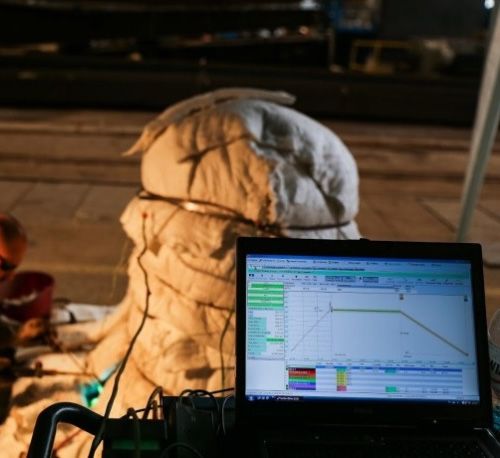
during the melting process. Zinc inclusions were also observed (Figure 3a, 5).This nega-
                           during the melting process. Zinc inclusions were also observed (Figure 3a, 5).This nega-
                            tively influenced the welding process.
                           tively influenced the welding process.
                                 A series of welding rods were made after chemical composition determination and
                                A series of welding rods were made after chemical composition determination and
                            consultations with the company conducting the welding process. Their composition was
                           consultations with the company conducting the welding process. Their composition was
Materials 2021, 14, 2504    selected to be as compatible as possible with the examined material of the bell. A6set  of
                                                                                                                of 10
                           selected to be as compatible as possible with the examined material of the bell. A set  of
                            molds was worked out and prepared in the Foundry Department, and thanks to them
                           molds was worked out and prepared in the Foundry Department, and thanks to them
                            welding rods of different lengths and diameters were produced (Figure 4).
                           welding rods of different lengths and diameters were produced (Figure 4).

                            Figure4.4.Welding
                                      Welding rodsofof different lengths and diameters  (the length  of rods was 40 the
                                                                                                                    cm;diameters
                                                                                                                         the diam-
                           Figure
                           Figure  4. Welding rods
                                              rods ofdifferent
                                                      differentlengths
                                                                lengthsand
                                                                        anddiameters
                                                                            diameters(the length
                                                                                       (the      of of
                                                                                            length  rods was
                                                                                                       rods  40 cm;
                                                                                                            was 40 cm;  the diam-
                            eters were 8 mm and 6 mm).
                           were were
                           eters 8 mm8and
                                        mm6and
                                             mm).6 mm).
                                 Thesize
                                The    sizeand
                                            andrange
                                                rangeofofthe
                                                          thecrack
                                                              crackwere
                                                                      were examinedwith
                                                                                      with theuse
                                                                                               use ofpenetration
                                                                                                       penetration testing
                                The  size and  range of  the crack   were examined
                                                                            examined with the
                                                                                          the use of
                                                                                                   of penetration testing
                                                                                                                   testing
                            (Figure 5).
                           (Figure 5).   Penetrator
                                   5). Penetrator   was
                                        Penetrator was   used
                                                   was used   for
                                                        used for   this
                                                             for this   examination
                                                                  this examination  by
                                                                       examination by  covering
                                                                                   by covering  the
                                                                                      covering the  crack
                                                                                               the crack  andfilm,
                                                                                                   crack and
                                                                                                         and   film,which
                                                                                                                     which
                           (Figure                                                                           film, which
                            helped
                           helped toto  determine
                                   to determine
                                      determine thethe range
                                                  the range  of
                                                      range of   the
                                                            of the    crack.
                                                               the crack.
                                                                     crack.
                           helped

                                               Figure 5. Penetration testing.
                                              Figure 5. Penetration
                                              Figure 5. Penetration testing.
                                                                    testing.

                                After crack range determination, mechanical treatment of the damaged place was
                           conducted to remove the external oxidized surface (Figure 5). This phase was performed
                           in such way to obtain the best access to whole crack by the welder during the welding
                           process (Figure 6). It was found during mechanical treatment that the bell’s structure is
                           very porous, especially the external surface. This worsened the welding process. The
                           welding process was conducted with the use of an oxyacetylene torch. During this process
                           the bell edges were melted with the welding rods made earlier. Welding was conducted
                           with the use of the “up method”. Better efficiency of welding and very good penetration of
                           the whole thickness of the connected parts were obtained thanks to this method. It was
                           possible to perform the weld with a single torch cut due to this method.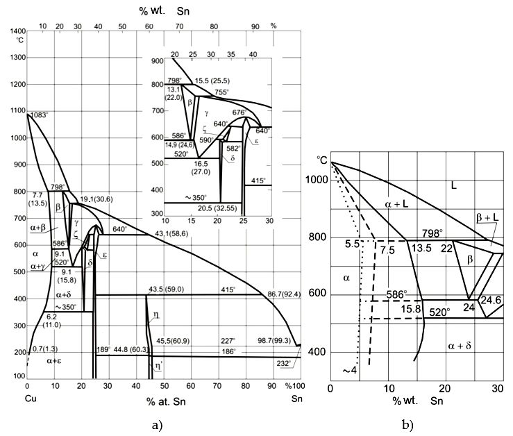
in such way to obtain the best
conducted access to
to remove whole
the crack
external by the surface
oxidized welder (Figure
during 5).
theThis
welding
phase was performed
process (Figure 6). It was found during mechanical treatment that the bell’s structure
in such way to obtain the best access to whole crack by the welder during is the welding
very porous, especially the external surface. This worsened the welding process. The
process (Figure 6). It was found during mechanical treatment that the bell’s structure is
welding process was
veryconducted with the use
porous, especially theofexternal
an oxyacetylene
surface. torch. During thisthe
This worsened process
welding process. The
the bell edges were melted with the welding rods made earlier. Welding was conducted
welding process was conducted with the use of an oxyacetylene torch. During this process
Materials 2021, 14, 2504 with the use of the “up 7 of 10
the bellmethod”. Better
edges were efficiency
melted of welding
with the weldingandrodsvery
madegood penetration
earlier. Welding was conducted
of the whole thickness of the
with the useconnected
of the “upparts were obtained
method”. thanks to
Better efficiency ofthis method.
welding andItvery
was good penetration
possible to perform the weld with a single torch cut due to this method.
of the whole thickness of the connected parts were obtained thanks to this method. It was
possible to perform the weld with a single torch cut due to this method.
Figure 6. Mechanical treatment of the damaged place.
Figure 6. Mechanical treatment of the damaged place.
Figure 6. Mechanical treatment of the damaged place.
It It
was important
was to heat
important toand
heatkeep
andthekeep
bell atthe
the bell
properat temperature
the proper during the weld-
temperature during the
ing process. This temperature
It was was obtained
important to heat by using
and keep heating mats and aluminosilicate
welding process. This temperature was obtained bythe bell at
using the proper
heating matstemperature during the weld-
and aluminosilicate
fiber isolation. The whole process oftemperature
heating waswas under the control of and recorded byand
a aluminosilicate
fiber isolation.ing Theprocess.
wholeThis process of heating obtained
was under bytheusing heating
control of mats
and recorded by
computer program (Figure
fiber 7);theThe
isolation. heating
wholerate was ~10
process of °C/h.
heatingThe
wastime of cooling
under the after per-
control of
a computer
forming program
the weld was longer(Figure
than 7);the heating
the(Figure
heating time,rate
and was
◦
~10 C/h.
the rate
cooling The~7time cooling after by a
ofThus and recorded
computer program 7);the heating wasrate~10was
°C/h. °C/h.
The time of cooling after per-
performing
slow theconducted
cooling was weld was longer than the which
heating time, and the cooling
bellrate was ~7 ◦ C/h.
forming theto avoid
weld wasstresses,
longer than thecould have
heating caused
time, the cooling
and the to crack
rate was ~7 °C/h. Thus
Thus slow cooling was conducted to avoid stresses, which could have caused the bell to
again. slow cooling was conducted to avoid stresses, which could have caused the bell to crack
crack again. again.
A
A
B
B
(a) (b)
(a)fibro isolation; red circle–the place of welding (b) (b)
Figure 7. Welding process (a) the bell protected by close–up of the place
of welding. A—acetylene torch, B—bronze rod.
Figure 7. Welding
Figure 7.process (a) the
Welding bell protected
process by fibro
(a) the bell isolation;
protected byred circle–the
fibro placered
isolation; of welding (b) close–up
circle–the place of of the place
welding
of welding. A—acetylene torch, B—bronze rod.
(b) close–up
After the of the place
cooling of welding.
process, A—acetylene
the place torch,
of welding was B—bronze
ground rod.8) and the sound
(Figure
of bell was examined. After the cooling process, the place of welding was ground (Figure 8) and the sound
Materials 2021, 14, x FOR PEER REVIEW After the cooling process, the place of welding was ground (Figure 8) and
8 of the
10 sound
of bell was examined.
of bell was examined.
Figure 8.
Figure 8. Welded
Weldedbell
bellattached
attachedto to
thethe
tower.
tower.
4. Sound Analysis of the Bell
In 2013, before the crack, the bell’s sound was analyzed. After welding and the ther-
mal stabilization process, this analysis was repeated. The sound of the bell, a G#4 note,
did not worsen or even improve as a result of the negligible reduction of the main aliquots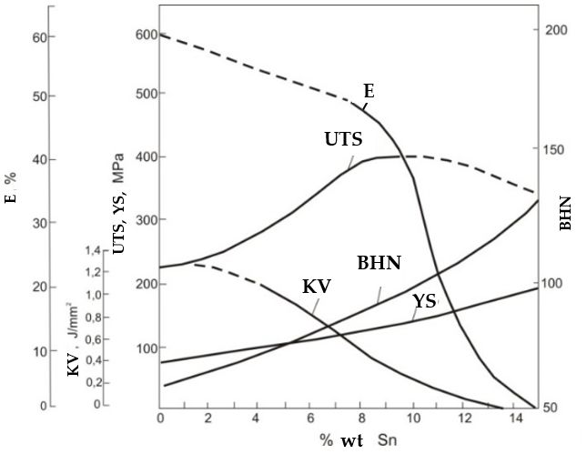
Materials 2021, 14, 2504                                                                                                     8 of 10

                                     4. Sound Analysis of the Bell
                                        In 2013, before the crack, the bell’s sound was analyzed. After welding and the
                                   thermal stabilization process, this analysis was repeated. The sound of the bell, a G#4
                                   note, did not worsen or even improve as a result of the negligible reduction of the main
                                   aliquots frequency.
                                        The target frequencies for the first partials are in the ratios 0.5:1.0:1.2:1.5:2.0 and these
                                   needed to be quite closely matched. The first aliquot, called the hum, is not prominent,
                                   and the perceived pitch is usually that of the second aliquot, called the prime, perhaps
                                   because it is reinforced by the harmonically-related aliquots with relative frequencies 2, 3,
                                   and 4. The tone of the bell is complex, however, particularly because of the presence of the
                                   minor-third (From Old French tierce, from Latin tertia) interval of 1.2 [10].
                                        The lower (tone lower than the prime about the octave) and upper (tone higher
                                   than the prime about the octave) octaves with prime, tierce and quint were found to be
                                   beautifully harmonious after the repair. There was no distortionary vibration and the bell
                                   sustained its note for a long time.
                                        The frequency spectrums of the Maryan bell before and after the crack are presented
                                   in Figure 9. The units of the amplitude in the figure are arbitrary; they are measured as
                                   voltages from a microphone, i.e., sound pressure levels on a linear scale. The amplitude
                                   of the spectrum is described in decibel scale. The program Wavanal [11] was used to
                                   analyze the sound of bell examined to determine the spectrum of emitted sound waves.
                                   This program was developed by W. A. Hibbert [12] for the sound analysis of bells to
                                   determine the influence of side tones on the height of the perceived strike tone (pitch tone).
                                   The possibility of fast and precise determination of their frequency was crucial, and the
                                   Wavanal program enabled it. This program allows a Fourier transform of sound waves
                                   directly recorded by a microphone joined to a computer or saved in a sound file recorded
                                   with other devices to be performed (Figure 10a,b). This program has received recognition
                                   among many bell makers as a great device for the evaluation of a bell’s sound and the
                                   process of tuning it up.
Materials 2021, 14, x FOR PEER REVIEW Determined by the Wavanal program, values of frequency of basic side tones (aliquots):                9
                                   the lower octave (hum), prime (fundamental), minor tierce, quint, and upper octave
                                   (nominal) of the bells examined are presented in Table 3 and as a diagram in Figure 11.

                                     Figure 9. The spectrum of the St. Maryan bell’s sound, before (BW) and after (AW) welding.
                                    Figure 9. The spectrum of the St. Maryan bell’s sound, before (BW) and after (AW) welding.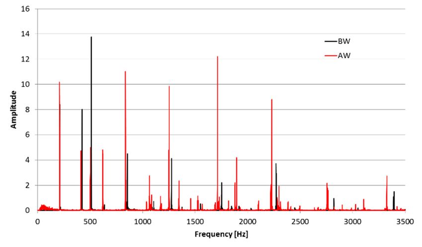
Materials 2021, 14, 2504 9 of 10
Figure 9. The spectrum of the St. Maryan bell’s sound, before (BW) and after (AW) welding.
(a) (b)
10. The
Figure 10. Theanalysis
analysisofof sound
sound wave
wave emitted
emitted by C3
by bell bellinC3 in program
program Wavanal;
Wavanal; (a) theofshape
(a) the shape of recorded
recorded wave, (b) wave, (b) its
its spectrum.
spectrum.
Table 3. Main partials of the St. Maryan bell’s sound frequencies before and after welding in
Determined
comparison by the
to harmonic Wavanal
tones program,
for the musical notevalues
G#4. of frequency of basic side tones (ali-
quots): the lower octave (hum), prime (fundamental), minor tierce, quint, and upper oc-
Partials Tone
tave (nominal) BW (Hz)
of the bells examined AW (Hz)
are presented in Table G#4 (Hz)
3 and as a diagram (ET) 11.
in Figure
Hum 212.5 208.5 207.6
Table 3. Main
Primepartials of the St. Maryan
422 bell’s sound frequencies
413 before and after welding
415.3 in com-
parison to harmonic tones for the musical note G#4.
Tierce 512 502.5 493.8
Partials
QuintTone BW635
(Hz) AW619
(Hz) G#4 622.3
(Hz) (ET)
Materials 2021, 14, x FOR PEER REVIEW
Hum 212.5 208.5 207.6 10 of 10
Nominal 853.5 836 830.6
Prime 422 413 415.3
Tierce 512 502.5 493.8
Quint 635 619 622.3
Nominal 853.5 836 830.6
Figure11.
Figure Themain
11.The main partials
partials of of
thethe
St.St. Maryan
Maryan bell’s
bell’s sound
sound frequencies,
frequencies, before
before (BW),(BW),
afterafter
(AW) (AW)
welding and for musical note G#4 according to the equal temperament scale
welding and for musical note G#4 according to the equal temperament scale (ET). (ET).
5.5.Conclusions
Conclusions
Basedon
Based onthe
the experience
experience gained
gained during
during the the
workwork
and and research
research carried
carried out onout
theon the
Mar-
Maryan bell, the following conclusions can be
yan bell, the following conclusions can be drawn:drawn:
1. If the welding process is carried out with the correct parameters, especially with
1. If the welding process is carried out with the correct parameters, especially with ther-
thermal ones, and with monitoring and control of the heating and cooling rates, the
mal ones, and with monitoring and control of the heating and cooling rates, the repair
repair even of contaminated high tin bronze bells is possible;
even of contaminated high tin bronze bells is possible;
2. After repair by welding, the bell has a “better” sound, and this is probably due to
2. After repair by welding, the bell has a “better” sound, and this is probably due to a
a kind of heat treatment performed, including a cycle of slow heating and cooling
kind of heat treatment performed, including a cycle of slow heating and cooling
which improves the properties of the material; and
which improves the properties of the material; and
3. The most highly recommended technique for repairing bells is gas welding, due to
3. The most highly recommended technique for repairing bells is gas welding, due to
the relatively low temperature in the bonding area and the efficiency of the process.
the relatively low temperature in the bonding area and the efficiency of the process.
Author Contributions: Conceptualization, methodology, software, formal analysis, writing—re-
view and editing, D.B.; conceptualization, methodology, investigation, writing—original draft prep-
aration, C.B. Both authors have read and agreed to the published version of the manuscript.
Funding: This research received no external funding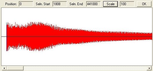
Materials 2021, 14, 2504                                                                                                        10 of 10

                                  Author Contributions: Conceptualization, methodology, software, formal analysis, writing—review
                                  and editing, D.B.; conceptualization, methodology, investigation, writing—original draft preparation,
                                  C.B. Both authors have read and agreed to the published version of the manuscript.
                                  Funding: This research received no external funding.
                                  Institutional Review Board Statement: Not applicable.
                                  Informed Consent Statement: Not applicable.
                                  Data Availability Statement: The data presented in this study are available in article.
                                  Acknowledgments: The authors would like to acknowledge to Rduch Bells and Clocks and Jan
                                  Felczynski’s Bell Foundry for materials and technical support.
                                  Conflicts of Interest: The authors declare no conflict of interest.

References
1.    Szupp, B. Repair of church bells by welding. Weld. Cut. Metals 1936, 12, 198–205.
2.    Ernesto Ponce, L. Restoration of ancient bronze bells. Part II: Welding. Ingeniare Rev. Chil. Ing. 2015, 23, 30–37. [CrossRef]
3.    Raimbault, L. Process for Welding Bells. Patent No FR2703615A1, 14 October 1994. France.
4.    Strafford, K.N.; Newell, R.; Audy, K.; Audy, J. Analysis of Bell Material from the Middle Ages to the Recent Time. Endeavour 1996,
      20, 22–27. [CrossRef]
5.    Audy, J.; Audy, K. Analysis of bell materials: Tin bronzes. China Foundry 2008, 5, 199–204.
6.    Bartocha, D.; Baron, C. The “Secret” of Traditional Technology of Casting Bells. Arch. Foundry Eng. 2015, 15, 5–10.
7.    Kurski, K. Cooper and Its Technical Alloys; Wydawnictwo Ślask:
                                                                   ˛ Katowice, Poland, 1967.
8.    Górny, Z.; Sobczak, J.J. Modern Casting Materials Based on Non-Ferrous Metals; ZA-PIS: Kraków, Poland, 2005.
9.    Górny, Z. Foundry Non-Ferrous Metal Alloys; WNT: Warszawa, Poland, 1992.
10.   Fletcher, N.H. The nonlinear physics of musical instruments. Rep. Prog. Phys. 1999, 62, 723–764. [CrossRef]
11.   Available online: http://www.hibberts.co.uk (accessed on 5 October 2020).
12.   Hibbert, W.A. The Quantification of Strike Pitch and Pitch Shifts in Church Bells. Ph.D Thesis, The Open University Milton
      Keynes, Milton Keynes, UK, 2008, in press.
You can also read