Understanding the dynamics of riser design in skyscrapers - Metraflex Technical Papers
←
→
Page content transcription
If your browser does not render page correctly, please read the page content below
Metraflex Technical Papers

 Understanding the dynamics of
 riser design in skyscrapers
How gravity, volume and thermodynamics play a
 role in smart riser design

 By Marty Rogin, PE; Engineering Manager, Metraflex

 www.Metraflex.com

 Page 1 of 15
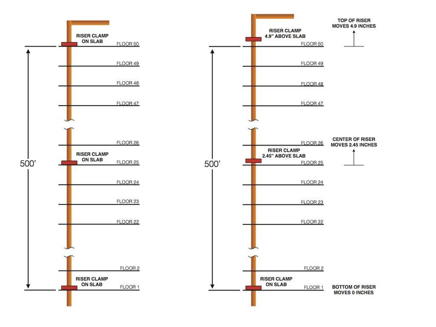
The modern skyscraper has been around for over a century. Like other elements of our built
 environment, the skyscraper can only exist because of other innovations in building technology, namely
 steel frame construction and safe elevators. Even though we have figured out how to build strong, tall
 structures and safely move the people inside, there are still the challenges of heating and cooling the
 building, moving fresh water in and dirty water out, providing fire protection and electricity. Defying
 gravity adds another twist to the challenges of providing services within tall buildings. This article will
 introduce some basics of pipe riser design and performance, explain some considerations in using
 different expansion joints in pipe risers, and briefly describe some of the codes and standards regarding
 guiding and supporting risers.

 Thermal Expansion Basics

 While the pipe is nothing special, gravity will make things way more interesting. Consider the riser pipe
 (Figure 1). The pipe runs the entire height of the building, 50 stories. If the slab-to-slab height is 10 feet,
 our pipe is 500 feet tall. A typical support for this pipe may be a riser clamp, maybe on every other
 floor. With no temperature change, the riser weight is distributed evenly between all the riser clamps.

 Figure 1: Riser
 Figure Priorprior
 1: Riser to Heating
 to heating

 Page 2 of 15
www.Metraflex.com
Let’s heat the water in the pipe (Figure 2). Now the pipe will expand against the supporting riser clamps.
 But the riser clamps are only restricted to move in one direction – down. There are no restrictions to
 upward movement. The clamps will just move up with the pipe. Any clamp above the bottom floor will
 now be floating above the slab. All the weight of the pipe, insulation and media is on the bottom clamp.
 Most pipe clamps are not designed to support the full weight of a tall riser.

 There are solutions. A pipe anchor at the bottom of the riser, designed to support the full riser weight,
 will solve this problem. But let’s look at how much the pipe moves. Let’s say our pipe is made of steel
 and the liquid medium is hot water at 180°F. Like gravity, thermal expansion (thermal strain) of steel
 will not disappear in a riser. If we assume an ambient temperature of 50°F, the pipe will want to expand
 according to the equation:

 ∆ =∝ ! ∆
 ∆ = Length change (inches)
 ∝ = Coefficient of thermal expansion (for
 steel, 6.33x10⁻⁶ inch/inch/°F)
 ! = Starting length (6000 inches)
 ∆ = Temperature change (180°-50° =
 130°F)

 ∆ = 4.9 inches

 The very top of the riser will move 4.9
 inches up. Is this a problem? It could be.
 Can the takeoffs at the upper levels
 move about 5 inches without breaking?
 Maybe, if there is enough runout length
 to the equipment connections. Will the
 field conditions allow the pipe to move
 this much before colliding with structure
 or equipment? Maybe, but then, who
 can answer these questions prior to
 construction? Usually they can’t be
 answered until the structure is up and
 the pipefitters install the pipes at the
 ceiling with all the unplanned bends and
 modified runout lengths.

 Figure
 Figure 2:
 2: Riser
 RiserAfter
 after Heating
 heating

 Page 3 of 15
www.Metraflex.com
One solution may be to move the anchor to the center of the riser (Figure 3). The anchor is a hard
 connection from the pipe to the structure and a point of zero movement. The riser is now divided into
 two sections, each 250 feet. Now the maximum pipe movement will be half of the entire riser, or 2.45
 inches. The previous questions may be asked regarding 2.45 inches of movement. If they can be
 answered during the design stage of a project, great! On to the next project!

 Figure 3: 3:
 Figure Riser With
 Riser Center
 with centerAnchor
 anchor

 But wait. What about those riser clamps? Above the anchor they will ride on the pipe, rising above the
 floors. But below the anchor, the riser clamps will try to restrain the pipe from moving downward. The
 likely outcome will be that the clamps will slip along the pipe as it moves. If the riser clamps are welded
 to the pipe, something will break – either the clamp or the pipe. Hopefully the clamp, but then the
 anchor will be carrying the load of the entire riser.

 Page 4 of 15
www.Metraflex.com
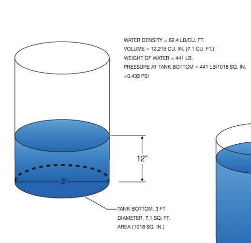
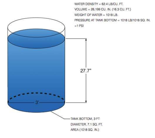
Riser Spring Supports

 And what about spring supports? These are specially-designed systems of anchors, guides and supports
 for risers that are designed to move with the pipe. The spring supports stay in contact with the floor
 slab as the pipe moves. As the pipe moves, the springs stretch or compress to exert more force on the
 floor slab, which takes load off the main anchor in the center of the riser. These systems are effective
 for taking the load off the main anchor; however, this type of system has limitations. These are:

 • The pipe still moves! Nothing will prevent this. If we use our 500 foot riser as an example, the
 anchor would be in the center, and the ends would move the same 2.45 inches.

 • Only one anchor is permitted in each riser. A second anchor will restrict the pipe movement,
 resulting in tremendous forces in the anchors and floor slabs while adding potentially huge
 stresses in the pipe.

 • It is unclear if this type of system can be adapted to copper risers. The available manufacturers’
 literature does not specifically mention copper as an acceptable pipe material for these support
 systems.

 A riser system using pipe riser clamps or spring supports will have limited control on the pipe
 movement. Expansion joints allow for better control of the pipe movement. Before looking at
 expansion joints, let’s consider what happens to the internal pressure of a riser.

 Pressure and the Height of a Water Column

 The internal pressure along a horizontal pipe axis generally varies a small amount. Once that pipe is
 tipped up to vertical, a fluid-filled riser builds pressure as the pipe gets taller. The pressure at the
 bottom can be significantly higher than at the top. This is due to the weight of the water.

 Consider a tank with 1 foot of water (Figure 4). No matter how full, the tank will experience more force
 on its walls towards the bottom. The most force will be at the bottom of the tank. Each added inch of
 water in the tank increases the weight that the bottom of the tank must hold. When the height of the
 water reaches 27.7 inches, there is 1 pound on each square inch of the bottom of the tank (Figure 5).
 Water Density = 62.4 lb/cu. ft. Water Density = 62.4 lb/cu. ft.
 Volume = 12.215 cu. in. (7.1 cu. ft.) Volume = 28.199 cu. in. (16.3 cu. ft.)
 Weight of water = 441 lb. Weight of water = 1018 lb.
 Pressure at tank bottom - 441 lb/1018 sq. in. Pressure at tank bottom - 1018 lb/1018 sq. in.
 = 0.433 psi = 1 psi

 27.7”

 Figure 4: Tank with Figure 5: Tank with
 12”
 1-foot water column 27.7” water column
 3’ 3’

 Tank bottom - 3 ft Tank bottom - 3 ft
 Diameter - 7.1 sq. ft. Diameter - 7.1 sq. ft.
 Area - 1018 sq. in. Area - 1018 sq. in.

 Figure 4: Tank with Figure 5: Tank with
 1 Foot Water Column 27.7" Water Column Page 5 of 15
www.Metraflex.com
Now, let’s change the shape of the tank to something narrower (Figure 6). As we move the tank walls
 closer, we need less water to fill the tank to 27.7”, but the tank bottom has a smaller area. The force on
 each square inch is still 1 pound.
 Water Density = 62.4 lb/cu. ft.
 Volume = 3130 cu. in. (1.8 cu. ft.)
 Weight of water = 113 lb.
 Pressure at tank bottom - 113 lb/113 sq. in.
 = 1 psi

 27.7”

 1’

 Tank bottom - 1 ft
 Diameter - 0.8 sq. ft.
 Area - 113 sq in.

 Figure 6:
 Figure 6: Smaller-Diameter
 Smaller-diameter tank,
 Tank,27.7”
 27.7"water
 Watercolumn
 Column

 It doesn’t matter what shape we make the tank, or even if it’s a pipe; if the water column is 27.7” tall,
 the pressure at the bottom is 1 psi.

 If we stack these 27.7” water columns, the pressure at the bottom builds in 1 psi increments (Figure 7).

 27.7”

 1 PSI

 27.7” 27.7”

 13 sq. in.

 1 PSI in the middle 2 PSI

 27.7” 27.7”

 2 PSI at the bottom 3 PSI at the bottom

 Figure 7: Stacked 27.7" (1 psi) Water Columns
 Figure 7: Stacked 27.7” (1 psi) water columns

 Page 6 of 15
www.Metraflex.com
The pressure at the bottom of the stack increases by 1 psi for each 27.7” section. Conversely, the
 pressure increases by 0.43 psi for each 12” section of water. Using this logic, the pressure at the bottom
 of our 500 foot riser that is only due to the height of the column of water will be:

 = 500 . 0.43
 = 215

 This is referred to as hydrostatic pressure, and it is why hydronic equipment is seldom located in the
 basement of a tall building. This is also why very tall buildings have risers that are subdivided between
 intermediate mechanical equipment rooms. For steam, gas and air, column height is not an issue due to
 the much lower density of these substances.

 Riser Structural Stability Considerations

 Column buckling is a familiar failure mode. If a long, slender bar is subjected to axial forces at each end,
 it will bow out (Figure 8). This is a function of the material strength, cross section dimensions and length
 of the bar. A pipe behaves like this too. Axial forces applied to the pipe ends will also make it bow out.
 This can be especially pronounced on small-diameter copper pipe.

 Although most of this bowing is elastic, meaning the pipe goes back to its original shape after the loads
 are removed, this can be a problem if the pipe bows beyond the elastic limit of the material. Column
 buckling can also be a problem with bellows expansion joints. If the two ends of a bellows are not
 within the offset movement limits, the expansion joint will be permanently damaged.

 Force

 Figure 8: Column buckling of a double-pinned bar (or pipe)
 Figure 8: Column Buckling of a Double-Pinned Bar (or Pipe)

 The pipe must remain aligned as it travels through the building. This is the purpose of pipe guides,
 which restrict the pipe to move only in the axial direction and essentially make the pipe more rigid.
 Guides divide the pipe into shorter, stiffer sections.

 The spacing of pipe guides is dictated by the classical column buckling equations, called the Euler
 buckling equations. If we assume the pipe is pinned on either end, the equation looks like this:

 !
 !" = ( 1)
 !
 !" =
 =
 = ( ! )
 = ℎ ( )

 This is the theoretical load limit for a column with the ends free to rotate and loads applied along the
 column axis. Notice that the weight of the pipe and water are not considered here. Euler buckling is an
 important consideration when bellows expansion joints are chosen for a piping system, especially risers
 as the forces are now acting along the pipe’s longitudinal axis.

 Page 7 of 15
www.Metraflex.com
If the pipe is fixed at one end (Figure 9) the critical load is:

 !
 !" = ( 2)
 4 !

 Force

 Figure
 Figure9:
 9:Column
 ColumnBuckling
 bucklingof
 of aaFixed-Pinned Bar (or
 fixed-pinned bar (or pipe)
 Pipe)

 What happens when the pipe is turned up on its end? Gravity. The weight of the pipe and media inside
 the pipe will now figure into the calculations. A riser pipe can theoretically collapse under its own
 weight (Figure 10). The critical load on a vertical pipe with the end fixed is:

 7.837
 ( )!" = ( 3)
 !

 ( )!" =

 q (Weight/Unit Length)

 Figure
 Figure10:
 10:Buckling
 Bucklingofofa Vertical
 a verticalFixed
 fixedSupport
 support Column Pipe) under
 column (or pipe) Underits
 itsweight
 Weight

 Page 8 of 15
www.Metraflex.com
Using the 4” pipe as an example and solving for the length with (ql)cr equal to 1.34 lb/in, the maximum
 length a vertical 4” sch. 40 can be is about 90 feet before becoming unstable. For comparison, a 4”
 type K copper riser will become unstable at about 64 feet. This is also the equation that determines the
 maximum height of a tree (neglecting the branches and assuming a prismatic trunk).

 Next, consider a riser having an external force like a bellows pressure thrust and spring force. A riser
 pipe under an external load subject to the weight of the pipe wall and media inside will have a critical
 load of:
 !
 !" = − 0.3 ( 4)
 4 !

 !" =
 =
 = ( ! )
 = ℎ ( )
 = ℎ ℎ , ( / )

 This equation assumes the end of the pipe is fixed and can’t rotate, the pipe has a constant cross section
 (same size all the way up) and that the weight is equally distributed. The critical load is reduced by 30%
 of the column weight. Note that the critical load can be negative, meaning that the top end support
 must be in tension to prevent buckling.

 The previous examples along with the hydrostatic pressure explanation are important for guide spacing
 in risers with different types of expansion joints. Let’s first consider a bellows expansion joint in a tall
 riser. How would we determine the pipe guide spacing for this type of installation?

 What are Pipe Guides?

 Pipe guides are devices that allow the pipe to move axially, while restricting the pipe from moving
 perpendicular to the pipe axis. By restricting the pipe to only axial motion, the pipe is more rigid and
 will not bow out or collapse. As the guides are placed closer along the pipe, the amount of axial loading
 can increase before the pipe becomes unstable.

 Common guides used for HVAC and plumbing systems are either finned or sliding. Finned guides, or
 “spider” guides, have fins fixed to the pipe and travel through a ring secured to the building structure.
 These guides are typically found on small-diameter pipe and are used for areas where the lateral loads
 are expected to be relatively small compared to the pipe anchor loads. In horizontal applications these
 guides are not intended to take the place of hangers, so a clevis or roller support would be required in
 the vicinity of the guide to hold the weight of the pipe.

 A more robust guide that can also function as a support is the sliding guide. This device has a sliding bar
 welded to the pipe, with a base secured to structure. The base has either Teflon, graphite or an
 elastomeric pad to reduce friction. This type of guide can handle greater lateral loads and is typically
 used on larger-diameter HVAC pipe or process piping. A version of the sliding guide adapted to risers
 incorporates an elastomer cushion between the slide and base to dampen noise and vibration of the
 pipe sliding against the slab penetration.

 Page 9 of 15
www.Metraflex.com
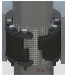
The most compact guide configuration consists of an elastomeric seal assembly within the slab
 penetration to guide the pipe. These take up no floor space in the riser chase and allow for the most
 efficient space usage.

 Spider Guide Slide Guide

 Sliding Riser Guide with Noise-Dampening Modular Riser Guide in Slab Penetration
 Elastomer

 Figure 11: Guides Commonly used in Risers

 Standards for Guide Placement with Bellows Expansion Joints

 According to the Expansion Joint Manufacturer’s Association (EJMA) standards, guides are required with
 bellows expansion joints at a maximum distance of four pipe diameters from the joint, then a maximum
 14 pipe diameters from the first guide for the next location. Subsequent guides are spaced at intervals
 dictated by the Euler buckling equation for a half pinned-column. When guides are placed according to
 EJMA guidelines, the pipe is subdivided into rigid sections that shouldn’t (theoretically) buckle under a
 known end load.

 Page 10 of 15
www.Metraflex.com
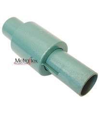
Guides with bellows expansion joints serve two purposes; to keep the pipes from buckling, and keep the
 Typical model codes require risers to be supported roughly at every floor. This is usually accomplished
 bellows from squirming (Figure 12). The EJMA standards assume a horizontal pipe, and the buckling
 with riser clamps. As described previously, the riser clamps may move upward and lose contact with the
 formula used divides the calculated length in half. For comparison, the 4” steel pipe with a bellows
 floor slab, depending on the anchor placement. Now the support is not doing its job, and all the load is
 expansion joint under 158 psi requires an intermediate guide spacing of 30 feet. The pipe is assumed to
 carried by the anchor. In this case, the codes were followed but the anchors may not be designed for
 be horizontal, so the weight of the pipe and media are not considered in the EJMA calculations.
 the entire weight of the pipe, insulation and its contents – plus any forces generated by the expansion
 Guides with bellows expansion joints serve two purposes; to keep the pipes from buckling, and keep the
 joints.
 Typical
 bellowsmodel codes require
 from squirming risers
 (Figure 12).toThe
 be supported roughly
 EJMA standards at every
 assume floor. Thispipe,
 a horizontal is usually accomplished
 and the buckling
 with riser clamps. As described previously, the riser clamps may move upward and lose
 formula used divides the calculated length in half. For comparison, the 4” steel pipe with a bellows contact with the
 floor slab, depending
 expansion joint underon158the
 psianchor
 requiresplacement. Now the
 an intermediate support
 guide is not
 spacing of doing its The
 30 feet. job, pipe
 and all the load is
 is assumed to
 carried by the so
 be horizontal, anchor. In thisofcase,
 the weight the codes
 the pipe were are
 and media followed but the anchors
 not considered may not
 in the EJMA be designed for
 calculations.
 the entire weight of the pipe, insulation and its contents – plus any forces generated by the expansion
 joints.
 Typical model codes require risers to be supported roughly at every floor. This is usually accomplished
 with riser clamps. As described previously, the riser clamps may move upward and lose contact with the
 floor slab, depending on the anchor placement. Now the support is not doing its job, and all the load is
 carried by the anchor. In this case, the codes were followed but the anchors may not be designed for
 the entire weight of the pipe, insulation and its contents – plus any forces generated by the expansion
 joints.

 Figure 12: Bellows squirm due to misaligned pipe
 Figure 12: Bellows Squirm Due to Misaligned Pipe

 Figure 12: Bellows Squirm Due to Misaligned Pipe
 Bellows Expansion Joints in a Riser

 Bellows expansion joints in risers are very common, mostly due to their compact shape (Figures 13 &
 14). They take up very little space perpendicular to the pipe axis, so they fit nicely in crowded pipe
 chases; however, they do need to be guided. The bellows will produce large anchor loads. This may be
 Figure 12: Bellows Squirm Due to Misaligned Pipe
 a necessary tradeoff, as space in pipe chases can be at a premium.
 Bellows Expansion Joints in a Riser

 Bellows expansion joints in risers are very common, mostly due to their compact shape (Figures 13 &
 14). They take up very little space perpendicular to the pipe axis, so they fit nicely in crowded pipe
 chases; however, they do need to be guided. The bellows will produce large anchor loads. This may be
 aBellows
 necessary tradeoff,
 Expansion as space
 Joints in pipe chases can be at a premium.
 in a Riser

 Bellows expansion joints in risers are very common, mostly due to their compact shape (Figures 13 &
 14). They take up very little space perpendicular to the pipe axis, so they fit nicely in crowded pipe
 chases; however, they do need to be guided. The bellows will produce large anchor loads. This may be
 a necessary tradeoff, as space in pipe chases can be at a premium.

 Figure 13: Externally-pressurized compensator Figure 14: Internally-pressurized bellows
 Figure 13: (Bellows
 Externally-Pressurized Compensator
 are inside housing Figure 14: Internally-Pressurized Bellows
 (Bellows are inside housing)
 Page 11 of 15
 Pipes in the vertical are now subject to hydrostatic pressure variations. These variations are simple to
www.Metraflex.com
 calculate, and will vary from the system operating pressure at the top of the riser to the height divided
 by 2.31 added to the system pressure at the bottom of the riser. Using the 500’ riser as an example with
Figure 13: Externally-Pressurized Compensator Figure 14: Internally-Pressurized Bellows
 (Bellows are inside housing)

 Pipes in the vertical are now subject to hydrostatic pressure variations. These variations are simple to
 calculate, and will vary from the system operating pressure at the top of the riser to the height divided
 by 2.31 added to the system pressure at the bottom of the riser. Using the 500’ riser as an example with
 a system pressure of 50 psi, the riser top will be at 50 psi and the bottom will be at 267 psi. This
 difference in pressure is critical in calculating the anchor loads for a bellows expansion joint.

 A bellows expansion joint installed near the bottom of a tall riser must be rated for the pressure at this
 location. In the previous example, a 150 psi expansion joint would be fine for the top section of the
 riser, but a joint near the bottom would require a higher pressure rating.

 And what about the anchor loads? Bellows expansion joints create reaction forces based on two
 characteristics of the bellows; the spring rate and the effective area. The spring rate is simply the
 amount of force required to compress or extend the bellows one inch. If a bellows has a 500 lb/inch
 spring rate, it will exert 500 pounds on each anchor for every inch of movement. If the bellows is
 compressed 1.5 inches, the spring force will be 750 lb. on each anchor.

 Pressure thrust may not be quite as straightforward. An expansion joint is the most flexible part of the
 piping system. It has to be this way. A bellows under pressure wants to stretch back to its original
 shape, which is a tube. If left unrestrained, a bellows under pressure will extend past its rated
 movement. This is why control rods and anchors are generally required for a bellows expansion joint.
 The amount of force exerted by the bellows on either the anchors or the control rods is also simple to
 calculate. It is the pressure multiplied by the bellows effective area.

 And what exactly is a bellows effective area? It is the inside area of the bellows, calculated at the
 average of the largest and smallest convolution diameters. This is also called the mean diameter. All
 bellows manufacturers provide the effective areas, so it is not necessary for the specifier to calculate
 this.

 If we use our 500’ riser as an example, a bellows expansion joint at the very top of the riser with a
 system operating pressure of 50 psi and a 4” pipe (with a 4” expansion joint) will have a pressure thrust
 on each anchor of:

 ℎ = !
 = ( )
 ! = ( . . )

 ! = 36 . . ( )
 = 50
 ℎ = 36 . . 50
 = 1800

 If we decide to split the riser and locate an expansion joint at the midpoint, the pressure used to
 calculate thrust force will be 50 psi added to the height of the water column above the expansion joint
 (about 250 feet):

 = 50 + 250 0.43 /
 = 158
 ℎ = 36 . . 158
 = 5688

 Now let’s add in the spring force. The riser will move 2.45 inches between each set of anchors. If the
 Page 12 of 15
 spring rate of the bellows is 200 lb/in:
www.Metraflex.com

 =
 = 50 + 250 0.43 /
 = 158
 ℎ = 36 . . 158
 = 5688

 Now let’s add in the spring force. The riser will move 2.45 inches between each set of anchors. If the
 spring rate of the bellows is 200 lb/in:

 =

 = 200 2.45

 = 490

 Friction from the pipe supports may be assumed to be very small for a riser, and will not be factored into
 these calculations. The total bellows force on the anchors will be:

 ℎ : 1800 + 490 = 2290

 ℎ : 5688 + 490 = 6178

 What about the weight of the pipe, water and insulation? This must be added to the bellows anchor
 loads to get the complete picture. And the lower bellows forces act upwards on the middle riser anchor,
 while the upper bellows forces act down on the anchor. It is important to not only keep track of the
 magnitude, but also the direction of the forces acting on an anchor. Additionally, the anchor is carrying
 the weight of the pipe and water from above. The intermediate anchor loading is more complicated if
 the expansion joint is centered between the anchors.

 We now have a situation similar to the critical loading for a riser under its own weight with an external
 force. If we look at our critical load equation (4) with pipe weight,

 !
 !" = − 0.3
 4 !

 and solve for the length using !" = 6178 lb, the guides would require spacing at 23 foot intervals, or
 maybe every other story.

 If a copper riser is installed, more guides would be required. The bellows forces would be roughly equal,
 as would the hydrostatic pressures. If the bottom half of the riser is once again considered, the only
 difference will be the material and cross-section properties of the copper pipe. For our 4” riser, the
 copper material and section properties are:
 = 17,000,000 ( )
 = 3.35 ! ( )

 Now the required guide spacing is at 12.5 foot intervals, or maybe at every story.

 Flexible Hose and Braid Loop Expansion Joints in Risers

 The only way to really limit the amount of movement in a riser is an expansion joint. Movement can be
 limited to any acceptable amount by anchoring the riser at various levels and installing an expansion
 joint between each anchor pair.

 Hose and braid expansion joints are another option for risers that provide many advantages over
 bellows expansion joints or spring support systems. Hose and braid expansion joints are typically
 constructed of two pieces of corrugated metal hose wrapped by metal braid. The joint may be
 fabricated in a ‘U’ or ‘V’ shape, which provides movement in all directions. Like the other expansion
 joint systems, hose and braid expansion joints are life-of-building products. They require no Page 13 of 15
 maintenance
www.Metraflex.com or inspections once installed.

 Hose and braid expansion joints offer several advantages over bellows or spring supports:
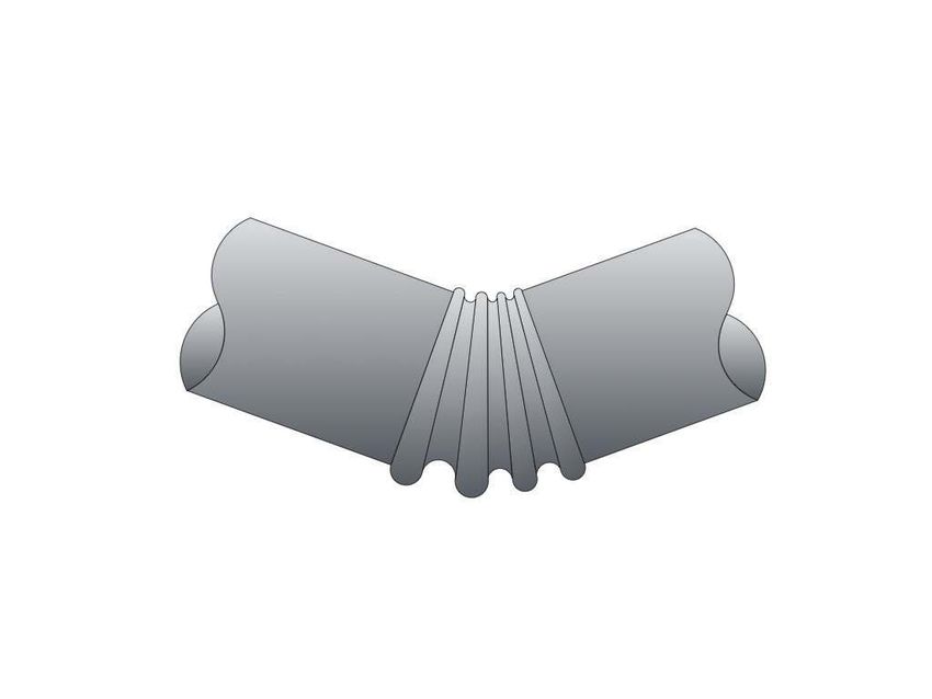
Flexible Hose and Braid Loop Expansion Joints in Risers

 The only way to really limit the amount of movement in a riser is an expansion joint. Movement can be
 limited to any acceptable amount by anchoring the riser at various levels and installing an expansion
 joint between each anchor pair.

 Hose and braid expansion joints are another option for risers that provide many advantages over
 bellows expansion joints or spring support systems. Hose and braid expansion joints are typically
 constructed of two pieces of corrugated metal hose wrapped by metal braid. The joint may be
 fabricated in a ‘U’ or ‘V’ shape, which provides movement in all directions. Like the other expansion
 joint systems, hose and braid expansion joints are life-of-building products. They require no
 maintenance or inspections once installed.

 Hose and braid expansion joints offer several advantages over bellows or spring supports:

 • No pressure thrust component. This is due to the hose and braid configuration and the braid
 restraining the hose from expanding.
 • Hose and braid expansion joints can be designed for operating pressures commonly found in
 HVAC and plumbing system pipe sizes.
 • Hose and braid sections are very flexible. The only anchor forces generated by these expansion
 joints are due to the spring forces of the hose and braid, which are typically less than 100
 pounds for many pipe sizes. The only other load on the anchor will be the weight of the full
 riser.
 • Hose and braid expansion joints can handle offsets in the riser much better than bellows
 expansion joints.

 Figures 15 and 16 show examples of hose and braid expansion joints commonly used in risers.

 Figure 15: Loop with 180º return Figure 16: V-loop
 Figure 15: Loop with 180° Return Figure 16: V-Loop

 The only potential disadvantage of hose and braid is the space requirement. Bellows expansion joints fit
 nicely in crowded pipe chases, hose and braid sticks out. Even this situation can be accommodated by
 mounting the loops horizontally in a ceiling chase.

 Hose and braid expansion joints subject the risers to small reaction forces, so the bottom half of a riser
 between anchors may be considered a free-standing length of pipe, similar Figure 10. This configuration
 would then follow a variation of equation (3) for the portion of riser below the expansion joint:

 7.837
 =
 !

 The term (q) is known, so the length for column stability (and guide spacing) can be determined by
 solving for the length l. Going back to the original example of a 500 foot, 4” sch. 40 pipe with a hose and
 braid connector in the center, the lower half would be subject to similar conditions as a riser of 250 feet
 with a fixed bottom. The required guide spacing would then be 10.6 feet. For type K copper, the
 required guide spacing would be only 4.1 feet.

 For the portion of pipe above the loop, one guide at the expansion joint would be adequate. Gravity is 14 of 15
 Page
 working in a favorable direction in this case.
www.Metraflex.com
The term (q) is known, so the length for column stability (and guide spacing) can be determined by
 solving for the length l. Going back to the original example of a 500 foot, 4” sch. 40 pipe with a hose and
 braid connector in the center, the lower half would be subject to similar conditions as a riser of 250 feet
 with a fixed bottom. The required guide spacing would then be 10.6 feet. For type K copper, the
 required guide spacing would be only 4.1 feet.

 For the portion of pipe above the loop, one guide at the expansion joint would be adequate. Gravity is
 working in a favorable direction in this case.

 Practical Considerations

 How often are guides placed every other story, let alone every single story in a high rise? Almost never.
 So why do we not have risers collapsing on every project? The answer may be simple; there are already
 guides at every floor, in the form of round slab penetrations. These allow axial movement and restrict
 lateral movement. Guide placement would be critical in an open chase, where pipes are routed through
 one single large floor penetration at each level.

 Also, most risers have takeoffs or runouts at each floor. If these are hard-piped to equipment in the
 vicinity of the riser, this arrangement can provide additional lateral support to the riser.

 Referring back to our original example of 4” steel pipe, EJMA guidelines don’t cover the case of a vertical
 31 foot
 pipe spacing
 with (or about
 zero loading every
 (like hosethree stories).
 and braid), andThis
 forauthor has observed
 the bellows exactly
 loading in zero riserrecommend
 this example, installationsa
 that comply with EJMA guidelines for guide spacing, and has yet to see a collapsed pipe riser.

 “Out of sight, out of mind” may also be part of the issue. The pipes may very well be bowing elastically,
 but nobody can see it. After all, how many architects will design windows on pipe chase walls? For that
 matter, how many tenants really care to observe their risers?

 Conclusion

 Although standards and codes address risers and guide spacing in pipes with bellows joints, it is
 important to know the limitations of the equipment and assumptions used to arrive at the
 recommended standards. Perhaps it’s appropriate to take a closer look at these standards and adapt
 them for tall risers.

 Building utilities have to be distributed to all levels, or there would be no point to a skyscraper.
 Assuredly, as long vertical pipes are placed inside tall buildings gravity will always act down, and building
 system designers should be aware of the forces on these elements. The petroleum industry is well
 aware of the design considerations on tall, flexible risers through experience with offshore drilling rigs.
 As we build taller structures, the A/E/C community must also be aware of similar – but not identical
 issues for conditions above the surface.
 References
 Sparks, C. P., Fundamentals of Marine Riser Mechanics, PennWell Corp., 2007
 Timoshenko, S. and Gere, J., Theory of Elastic Stability, McGraw-Hill, 1961

 Metraflex offers delegated design assistance and technical support.
 Contact your local Metraflex representative or visit us at
 Metraflex.com

 Page 15 of 15
www.Metraflex.com
You can also read