Technological Capabilities of Well Cementing - Sciendo
←
→
Page content transcription
If your browser does not render page correctly, please read the page content below
Technological Capabilities of Well Cementing

doi:10.2478/mape-2021-0042
Date of submission to the Editor: 03/2021             MAPE 2021, volume 4, issue 1, pp. 465-478
Date of acceptance by the Editor: 06/2021

Tatiana N. Ivanova
ORCID ID: 0000-0003-2284-2949
Tchaikovsky Branch
“Perm National Research Polytechnic Institute”,
Federal State Budgetary Institution
of Science “Udmurt Federal Research
Center of the Ural Branch of the Russian Academy
of Sciences“, Institute of Mechanics, Russia

Michał Zasadzień
ORCID ID: 0000-0002-3181-9815
Silesian University of Technology, Poland

ANALYSIS OF EXISTING SCHEME OF CEMENTING
In the current practice, cementing unit TSA-320 (ЦА-320, Russia), cement
mixing unit (2SMN-20) and manifold unit (BM-700) are used on the most of fields
(Savenok et al., 2020; Moroz et al., 2020; Afanasyev 2012; Baranov et al.,
2017).
Cementing truck TSA-320 (Fig. 1) is used for pumping of fluids during well
cementing in the process of drilling or workover, as well as for other flushing and
squeezing operations on oil and gas wells. To provide the operation under low
temperatures, cementing units are equipped with a device for heating of
hydraulic part of high-pressure pumps. They are also equipped with a system
for monitoring the temperature of the oil in the pump crankcase NTS-320 (НЦ-
320) with information output to the car dash panel. TSA-320 has a manifold to
ensure the simultaneous operation of several units when cementing wells and
the adapter for connecting the suction hose to the suction line.

                                   Fig. 1 Cementing truck (TSA-320)

Cement mixing unit 2SMN-20 (2СМН-20) is designed for transportation of dry
grouting materials, regulation of the supply of these materials by screw
conveyors and preparation of grouting slurries for cementing oil and gas wells.
The cement mixing unit consists of a hopper with two working screw conveyors
and one loading screw conveyor with a folding bottom part, a power take-off box,

  Contact address: tatnic2013@yandex.ru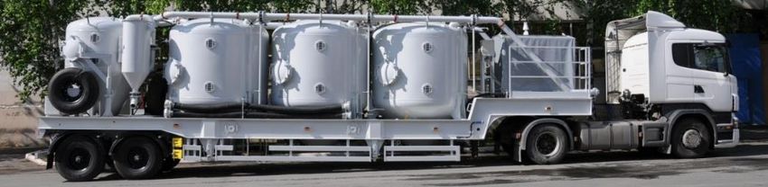
466         Multidisciplinary Aspects of Production Engineering – MAPE vol. 4, issue 1, 2021

a loading conveyor drive, a jet-type hydraulic mixing device with replaceable
slotted nozzles and a control panel located at the rear of the unit.
Manifold unit BM-700 (БМ-700, Russia) (Fig. 2) is designed for connection of
pumping units to each other and to wellhead equipment during pumping of fluid
in a well.

                                   Fig. 2 Manifold unit

Standard piping scheme of cementing equipment is shown on Figure 3.

                      Fig. 3 Scheme of piping of cementing equipment:
   1 – cement casing head; 2 – manifold unit (BM-700); 3 – cementing truck (TSA-320)
   involved in installation of a cement plug; 4 – control station SKUPTS-K (СКУПЦ-К);
  5 – mud surge tank; 6 – cementing trucks (TSA-320) involved in injection of cement
 slurry and spacer fluid in a well; 7 – cementing trucks involved in injection of spacer
 fluid in a well; 8 – cementing truck (TSA-320) involved in injection of mixing fluid and
    spacer fluid in a well; 9 – cementing truck (TSA-320) involved in mixing of cement
   slurry; 10 – cement mixing unit (2SMN-20); 11 – mud hopper; 12 – mixing fluid and
 spacer fluid supply line; 13 – pressure line; 14 – containers for preparation of mixing
                                    liquid (spacer liquid)

In total, 13 units of equipment are involved in the cementing process. All of them
must be tied and coordinated. According to the work procedure and safety
requirements, 2 employees should work on each cementing unit, 1 employee on
each cement mixing machine, 1 employee at the control station, 1 employee on
the manifold unit. So, to carry out the operation we need 19 employees on
equipment and also one manager, who will be responsible for the operation.
Injection of cement slurry involves only two 2 TSA-320, while squeezing of slurry
by a spacer liquid requires 4 TSА-320. The maximum injection rate of the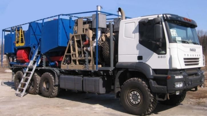
Engineering and Technology                                                   467

cement slurry is 12 liters per second, and the maximum delivery rate of the
spacer fluid is 24 liters per second.
In order to determine the time required for cementing and allowable pressures
during this procedure, the cementing process was simulated in the software
"BursoftProject" (Russia). The simulation results are presented in the diagrams
in Figures 4-8.

                 Fig. 4 Plan of injection and squeezing with TSA-320

                      Fig. 5 Plan of safe squeezing with TSA-320

                                                   Friction loss

                    Fig. 6 Pressure on TSА-320 during cementing

Calculated total time for cementing operations is 83.9 min, which is almost equal
to maximum allowable time of 90 min (0.75х120 min thickening time).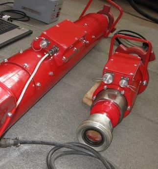
468        Multidisciplinary Aspects of Production Engineering – MAPE vol. 4, issue 1, 2021

       Fig. 7 Bottom-hole pressure in the process of cementing with TSA-320

                  Fig. 8 Equivalent density of fluid (EDF) in motion
                    and static compared with pressure gradients

The highest hydrodynamic pressure is created in a well during cement slurry
squeezing. The hydrodynamic pressure does not exceed the limit when the
spacer fluid is supplied with TSA-320 at a rate of 24 liters per second.
The maximum pressure is created on TSA-320 in the end of squeezing process
and it reaches 121.19 atm. It does not exceed the maximum allowable pressure
on TSA-320 on the third gear which is 14 MPa (138.2 atm).
During all cementing process, hydrodynamic pressure on the bottom of the well
does not exceed fracture pressure and always 10% higher than reservoir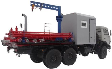
Engineering and Technology                                                     469

pressure. Therefore, drilling under these conditions will not lead to oil and gas
showings and fracturing of rocks near the shoe.
Since the fracture pressure gradients change nonlinearly with deepening of the
well, it is necessary to simulate the hydrodynamic effect on the borehole walls
throughout the wellbore. The greatest pressure is exerted on the borehole walls
at the end of the cementing. The diagram (Fig. 8) shows the equivalent pressure
at the end of cementing. The equivalent dynamic density of the cement slurry
does not cause hydraulic fracturing in this horizon.
According to the results of modelling of cementing process, the next conclusions
can be made:
1) The total time for cementing and squeezing is 83.9 minutes. This is close to
     the value of 90 minutes, which is the maximum permissible according to
     safety rules for the used cement slurry. Therefore, there are big
     technological risks of cementing, as slight violation of the cement slurry
     formulation can cause decrease in the thickening time or the sudden
     increase in time of the cementing operation by more than 6 minutes. The
     hydrodynamic pressures may increase until the pumping of the cement
     slurry stops and cement can stay inside the casing.
2) Pressure losses during cementing are 121.19 atm, maximum allowable
     pressure on TSА-320 is 138.2 atm. In case of an increase in viscosity,
     dynamic and static shear stresses also grow and pressure can exceed the
     value allowed for third gear. It will cause one of the units to stop, pressure
     will grow further leading to a forced shutdown of all the units. Then the
     squeezing process will be resumed on the second gear with a flowrate of
     3.2 liters per second on each unit, which will result into exceeding of
     allowable cementing time.
3) Hydrodynamic pressure of cementing does not exceed fracture pressure of
     all layers.

PROPOSED TECHNOLOGICAL SOLUTION
To optimize the cementing technique the main ways to improve the process are
increasing fluid supply capabilities, decreasing the amount of equipment units
and reducing the number of maintenance staff. From the technological view, an
increase in fluid supply capability provides the better displacement, creation of
faster turbulent flow and decreases the time of cementing. A decrease in amount
of equipment units and reduced maintenance personnel increase the safety of
the process.
It is proposed to use a cementing complex of a new type, which includes:
pumping facility UNBS2-600х70 (УНБС2-600х70, Russia); mobile cement bulk
storage TsT-40-m02-01 (ЦТ-40-м02-01, Russia); cement carrier TsT-25-M-02
(ЦТ-25-М-02, Russia); cementing control station SKTsS-01 (СКЦС-01, Russia);
TSA-320 (for water injection); water carriers (Dzhus et al., 2020; Andrusyak et
al., 2017; Lao & Zhou 2016; Li et al., 2019; Velychkovych et al., 2020;
Grechnikov et al., 2018; Wang & Liu 2017, Ivanova & Zabinska, 2021).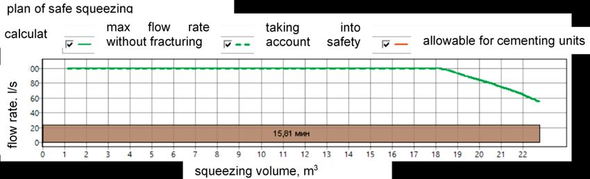
470 Multidisciplinary Aspects of Production Engineering – MAPE vol. 4, issue 1, 2021
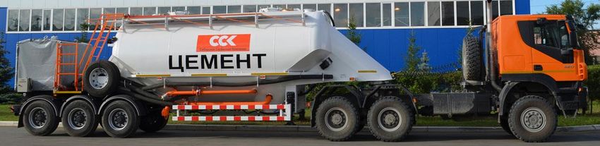
Pumping facility UNBS2-600х70 (Fig. 9) is designed for pumping of cement and
nonaggressive operating fluids into oil & gas wells in during cementing, jet
perforation, sand washing, flushing and pressurizing operations during well
stimulation and workover. The facility is equipped with recirculation system of
continuous preparation and mixing of cement slurries. It consists of a mixing unit
with pneumatic supply of dry cement and water and two tanks: mixing tank and
surge tank, equipped with hydraulically driven agitators.
Fig. 9 Pumping facility UNBS2-600х70
The presence of two more powerful high-pressure pumps allows carrying out
several operations simultaneously and decreases the probability of formation of
plugs during injection of the slurry in a well. An enhancement of functions of
such facility allows replacement of two pumping facilities and several mixing and
surge tanks, which considerably decreases the expenses on cementing
equipment and its maintenance. In addition, it allows decreasing labor input and
energy consumption. What is more, the presence of heating system for drive
and hydraulic parts of high-pressure pump, which is not included in common
pumping units, allows using it in cold climate. The presence of the automatic
system for preparation of cement slurry and density sensor in the recirculation
system of the facility provides control of the density of prepared slurry without
stopping the cement blending process. The rational assembly of the
UNBS2-600x70 facility provides convenience for operators when servicing the
unit.
Mobile cement bulk storages «TsТ-40» (ЦТ-40, Russia) (Fig. 10) are designed
for saving the quality of dry cement and supplying of cement flour into mixing
unit. The unloading of the transported material is carried out using compressed
air. The total geometrical capacity of the containers does not exceed 40 m3.
Fig. 10 Mobile cement bulk storage TsТ-40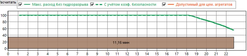
Engineering and Technology                                                     471

Semitrailer cement carrier (Fig. 11) is designed for transportation of dry cement
and other bulk materials with density up to 1.5 g/cm 3. The unloading of the
transported material is carried out using compressed air. The geometric capacity
of the tank does not exceed 25 m 3. The mass of the transported cargo should
not exceed 30 tons. The number of sections in the tank can vary from 1 to 4.

                             Fig. 11 Cement carrier TsT-25

Let us study the work of the station on the typical example of well cementing.
We assume that single-stage cementing of annular space of surface pipe is
required. Based on the parameters of well construction, the work plan is made;
it includes description of steps and pumping volumes. Initial planned parameters
are introduced into software of the station. The measuring tube of the station is
mounted in the discharge line after the manifold unit right before the cementing
head. Anything that enters the well passes through the measuring tube. The
signals from the sensors of the monitored parameters are converted by the
controller into a digital electrical signal, which is transmitted to the operator's
workplace. Data can be transmitted either through the power cable through the
power supply, or through the radio link (Fig. 12).

             Fig. 12 Сontrol station of technological operations SKTsS -01

According to the proposed scheme of well cementing, the following equipment
is required: 1 dual pump cementing unit with mixing section, 1 mobile cement
bulk storage, 2 cement carriers, 1 control station of cementing, 2 water carriers
and 1 TSA-320 for water supply. To sum up, 8 units of equipment are required.
The productivity of the new dual pump unit is 1 ton per minute for solution
preparation, and up to 34 liters per second for injection into the well. The new
cementing complex is used for injection; the UNBS2-600x70 facility is involved
in the work. Environmental safety is among the main advantages of the new
cementing complex. Technical fluid and drilling mud do not spill and, as a result,
expenses for cementing of the production string are reduced. Typical complexes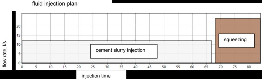
472          Multidisciplinary Aspects of Production Engineering – MAPE vol. 4, issue 1, 2021

carry out work both on the territory of the Russian Federation and in the far and
near abroad.
The layout of the proposed complex is shown in Fig. 13.

      Fig. 13 Equipment layout during cementing operations involving UNBS2-600/70

In order to determine production parameters with the use of new cementing
equipment, the cementing process was simulated in the software
"BursoftProject". The simulation results are presented in the diagrams in Figures
14-18.

               Fig. 14 Plan of injection and squeezing with UNBS2-600x70

                              Fig. 15 Plan of safe squeezing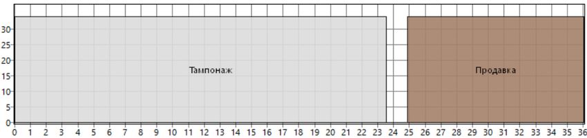
Engineering and Technology                                               473

Maximum output of UNBS2-600x70 high-pressure pumps is 34 liters per
second. With this supply of cement slurry and spacer fluid the total time of
cementing will be 36.05 min.
Hydrodynamic pressure does not exceed the limit under pumping rate of 34 l/s.
Maximum allowable flowrate is 55.1 liters per second.

                   Fig. 16 Pressure on equipment during cementing

Maximum pressure is created on the UNBS2-600x70 pump in the end of
squeezing and it reaches 129.6 atm. Maximum allowable pressure for
UNBS2-600x70 is 50 MPa (493.5 atm), and it is not exceeded during cementing.

              Fig. 17 Bottom-hole pressure in the process of cementing
474 Multidisciplinary Aspects of Production Engineering – MAPE vol. 4, issue 1, 2021
During all cementing process, hydrodynamic pressure on the bottom of the well
does not exceed fracture pressure and always 10% higher than reservoir
pressure. Therefore, drilling under these conditions will not lead to oil and gas
showings and fracturing of rocks near the casing shoe.
The greatest pressure on the borehole walls is reached at the end of the
cementing. The diagram (Fig. 18) shows the equivalent pressure at the end of
cementing. The equivalent dynamic density of the cement slurry does not cause
hydraulic fracturing in the layer.
Fig. 18 Pressure gradients for layers and cementing hydrodynamics
According to the results of modelling of cementing process, the next conclusions
can be made:
Total time of cementing operations is 36.05 minutes. Maximum permissible
value according to safety rules for the used cement slurry is 90 minutes;
Maximum pressure during cementing using UNBS2-600x70 is 129.6 atm and it
does not exceed the maximum allowable value of 493.5 atm;
During cementing the pressure is distributed along the borehole, so it does not
exceed the fracture pressure.
Technological efficiency
Proposed solution involving implementing of new cementing complex has the
next technological effect:
• Decrease in cementing time from 83.9 to 36.05 minutes;
• Prevention from technological risks, connected with pressure limit in case of
pumping with TSA-320 and cementing time;
• Increase in flow rate and speed of pumping of cement slurry, which improves
the quality of cementing due to turbilization of the flow;Engineering and Technology 475
• Decrease in the environmental damage, connected with spilling of
technological fluids during cementing;
• Increase in safety of carried operations due to bigger spacing between
equipment units and due to reduced amount of equipment units;
• Decrease in risk of human error due to reduced maintenance personnel and
automatization of the process.
Proposed method of cementing with involves 8 equipment units, which require
10 employees.
Table 1 Services for cementing of production casing
Proposed complex
Standard method
of equipment
Service Meas. Price,
description unit rub. Cost Quantity Cost Quantity
of of
services, services,
rub rub
Work of TSA,
hours 2951.89 60218.56 20.4 1771.13 0.6
UNB 160·40
Mileage of TSA,
km 88.87 106644 1200 17774 200
UNB 160·40
Preparation
t 611.17 79818.8 130.6 79818.8 130.6
of dry mixture
Work of mobile bulk
cement storage hours 2903.42 7548.89 2.6
TsT-40М-01
Mileage of mobile bulk
cement storage km 290.28 58056 200
TsT-40М-01
Work of TSA,
hours 11420.58 29693.51 2.6
UNBS 600·70
Mileage of TSA,
km 275.22 55044 200
UNBS 600·70
Technological stand-by
of cement carrier hours 2233.96 5808.3 2.6
TsT-25М-02
Technological stand-by
of water carrier with
hours 1496.27 3890.3 2.6
volume exceeding
3
20 m
Mileage of water carrier
with volume exceeding km 49.59 9918 200
20 m3
Work of cement carrier
with carriage up to hours 771 1542 2 1542 2
8999 kg
Cement carrier tag out pcs 49.63 198.52 4 198.52 4
Work of SKTs hours 1425.55 4846.87 3.4 3706.43 2.6
Mileage of SKTs km 47.51 9502 200 9502 200
Work of TsPSA hours 1570.67 31413.4 20
Mileage of TsPSA km 53.86 53860 1000
Filling of TsPSA
t 68.8 8985.28 130.6
on the base
Work of surge unit hours 1625.91 5528.09 3.4 4227.37 2.6
Mileage of surge unit km 54.02 10804 200 10804 200
TsPSA tag out pcs 86.91 434.55 5
Planned accumulations
4% 15005.96 11972.13
(4%)
In total: 388802.03 311275.38476 Multidisciplinary Aspects of Production Engineering – MAPE vol. 4, issue 1, 2021 For the purpose of a comprehensive assessment of economic efficiency, it is necessary to calculate the cost of the operation according to the time standards and parameters of the projected well. The next parameters were accepted for calculation: the distance to the drilling site and back is 200 km, preparation and filling of 130.6 tons of cement (according to calculation in section 2), equipment set-up time is 2 hours, cementing time for standard method is 1.4 hours (according to simulation in section 5), cementing time with new complex of equipment is 0.6 hours (according to simulation in section 5). The cost calculation shows the prices of OOO Tatburneft – LUTR. The calculation results are demonstrated in Table 1. The payback of the equipment and the wages of the maintenance personnel are included in the cost of services. Consequently, the economic effect of one operation on the example of the given well is 77526.65 rubles. SUMMARY New cementing complex includes up-to-date pumping facility UNBS2-600х70 (УНБС2-600х70), mobile cement bulk storage TsT-40-m02-01 (ЦТ-40-м02-01), cement carrier TsT-25-M-02 (ЦТ-25-М-02), control station, water carriers and one TSA-320 for water supply. In comparison with standard scheme of cementing, the new complex provides increased supply of fluids, which has a positive effect on cementing quality and speeds up the process. Quality of cementing grows due to turbulization of the flow, which contributes to better filling of annular space by cement. The most meaningful improvement is reducing of cementing time. The cementing process was modeled and it was found out that the cementing of the given well using standard method takes 83.9 minutes. This time for pumping of fluids is very close to the maximum allowed time for work – 90 minutes (75% of 120 minutes of thickening). In addition, the pressure at the end of the displacement is 121.2 atm, which is close to the maximum allowable value for the TSA-320 in 3rd gear – 138.2 atm. This increases the risks of the operation. Working with a new cementing complex allows reducing the pumping and squeezing time to 36.05 min. This reduces technological risks and also opens up opportunities for improving the cement slurry formulation towards reducing the thickening time and, as a consequence, reducing the waiting-on-cement. The acceleration of the process by 47.85 min is one of the positive economic effects. To a greater extent, the economic effect consists of a decrease in the equipment and personnel involved in the work. The standard cementing scheme involves 13 units of equipment and 19 employees, and with the use of the new complex, 8 units of equipment and 10 employees are involved. Despite the fact that the equipment of the new complex is more expensive, the total cost of cementing will be lower. The total economic effect on the example of the projected well is 77.5 thnd rub. Technological and environmental efficiency confirms the feasibility of using the new complex.
Engineering and Technology                                                             477

ACKNOWLEDGEMENT
This paper was financed from the resources of the Silesian University of
Technology, project no. 13/010/BK_21/0057.

REFERENCES
Afanasyev V.A. (2012) “Optimization of well assemblies and well pump equipment of
      dual completion”. Engineering Practice, no 2, pp. 36-38.
Andrusyak A., Grydzhuk J., Dzhus A., Steliga I. (2017) “Developing a method for the
      assessment of axial load in arbitrary cross-sections of the column of pumping
      rods”, Eastern-European Journal of Enterprise Technologies, vol. 1, no. 7, pp. 32-
      37. doi:10.15587/17294061.2017.92860
Baranov M.N., Božek P., Prajová V., Ivanova T.N., Novokshonov D.N., Korshunov A.I.
      (2017) “Constructing and calculating of multistage sucker rod string according to
      reduced stress”. Acta Montanistica Slovaca, vol. 22, no. 2, pp. 107-115.
Dzhus A., Rachkevych R., Andrusyak A., Rachkevych I., Hryhoruk O., Kasatkin S.
      (2020) “Evaluation the stress-strain state of pumping equipment in the curvilinear
      sections of the wells”. Management Systems in Production Engineering, Vol. 28,
      pp. 189-195 doi:10.2478/mspe-2020-0028
Grechnikov F.V., Rezchikov A.F., Zakharov O.V. (2018) Iterative Method of Adjusting
      the Radius of the Spherical Probe of Mobile Coordinate-Measuring Machines
      When Monitoring a Rotation Surface. Measurement Techniques. Vol. 61, pp. 347-
      352.
Ivanova T.N., Żabińska I. (2021) “Modern Methods of Elimination of Lost Circulation in
      Directional Wells”. Management Systems in Production Engineering”. vol. 28,
      issue 1, pp. 65-74. doi:10.2478/mspe-2021-0009
      L.-M. Lao, H. Zhou (2016) ”Application and effect of buoyancy on sucker rod string
      dynamics”, Journal of Petroleum Science and Engineering, vol. 146, pp. 264-271.
      doi:10.1016/j.petrol.2016.04.029
Li Q., Chen B., Huang Z., Tang H., Li G., He L. (2019) “Study on Equivalent Viscous
      Damping Coefficient of Sucker Rod Based on the Principle of Equal Friction
      Loss”, Mathematical Problems in Engineering. doi:10.1155/2019/9272751
Moroz L., Uhrynovskyi A., Popovych V., Busko B., Kogut G. (2020) “Effectiveness
      research of physical and chemical methods appfication for oil recovery enhancing
      using the asp for the strutynsky oil field conditions”. Management Systems in
      Production Engineering, Vol. 28, Issue 2, pp. 104-111. doi:10.2478/mspe-2020-
      0016
Savenok O.V., Povarova L.V., Kusov G.V. (2020) “Application of superdeep drilling
      technology for study of the earth crust”. IOP Conference Series: Earth and
      Environmental Science. pp. 052-066.
Wang D.-Y., Liu H.-Z., (2017) “Dynamic modeling and analysis of sucker rod pumping
      system in a directional well”, Lecture Notes in Electrical Engineering, vol. 408, pp.
      1115-1127. doi:10.1007/978-981-10-2875-5_90
Velychkovych A., Petryk I., Ropyak L. (2020) “Analytical Study of Operational
      Properties of a Plate Shock Absorber of a Sucker-Rod String”, Shock and
      Vibration. doi:10.1155/2020/3292713
478 Multidisciplinary Aspects of Production Engineering – MAPE vol. 4, issue 1, 2021 Abstract: Cementing of casing string is a final operation before the next stage of well construction; it provides maximum operational life of the well. Cementing of casing string is carried out with the use of technology, based on squeezing of the whole volume of drilling mud by special grouting composition. The main purposes of cementing include isolation of water-bearing horizon, strengthening of borehole walls in unconsolidated and unstable rocks. Well cementing process is divided into five subsequent operations. Firstly, grouting mixture is prepared in concrete mixers (cementing units) with necessary water-to-cement ratio and additives. Secondly, prepared grouting solution is injected in a well. Thirdly, the solution is squeezed into the space between the casing pipes and wellbore walls. Then it is necessary to wait until the cement sheath is hardened. And at last, quality control is carried out. For convenient transportation, the equipment for well cementing is installed on the truck chassis (KAMAZ, URAL and etc.). All components are poured in concrete mixer, then the water is added and everything is being mixed until formation of uniform mass, which is later pumped in a well. Oil and Gas Industry Safety Regulations say that «calculated endurance of casing string cementing should not exceed 75% of time of cement thickening, established by laboratory tests». Therefore, it is necessary to carry out all operations of injection of fluids into the well as soon as possible without any incompliances of the cementing technology. With cementing material used and its water-to-cement ratio of 0.5, the average time of cement thickening is 120 minutes, according to laboratory tests. Therefore, a set of operations of injection of fluids should not exceed 90 minutes. Keywords: cementing of casing string, isolation of water-bearing horizon, cement slurry injection, squeezing
You can also read