Influence of cement slurry heat release on physical properties of marine hydrate reservoirs during well cementing
←
→
Page content transcription
If your browser does not render page correctly, please read the page content below
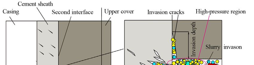
E3S Web of Conferences 228, 01017 (2021) https://doi.org/10.1051/e3sconf/202122801017
CCGEES 2020

 Influence of cement slurry heat release on physical properties of
 marine hydrate reservoirs during well cementing
 Mingming Zheng1,2,*, Xiaoyu Wang1, Zhilin Wang1, Kerui Zhou1, Kai Wang1, Gang Dong3 and Tianle Liu4,
 1StateKey Laboratory of Geohazard Prevention and Geoenvironment Protection, Chengdu University of Technology, Chengdu 610059,
 China
 2Key Laboratory of Tectonics and Petroleum Resources Ministry of Education, China University of Geosciences(Wuhan), Wuhan 430074,

 China
 3Qinghai Research Institute of Survey and Design of Water Conservancy and Hydropower,Xining 810012, China
 4Engineering Research Center of Rock-Soil Drilling & Excavation and Protection, Ministry of Education, China University of Geosciences

 (Wuhan), Wuhan 430074, China

 Abstract. Natural gas hydrates gradually become the focus of new energy resources, and the study of hydrate
 exploitation is growing vigorously during recent years. Well cementing is an important process during energy
 exploitation, especially when encounters hydrate bearing sediments in deep-water oil and gas drilling,
 showing great research significance and becoming a research hotspot. In this study, the exploratory well of
 SH2 of GMGS-1 project is chosen as the object of study, a cementing model of two dimensions based on this
 exploratory well is build, the invasion process of cement slurry is reappeared by TOUGH+HYDRATE, and
 the physical properties response of hydrate reservoirs during the cementing process is analyzed based on the
 numerical simulation data. In which, a view of "continuous stage simulation" to solve the problem of dynamic
 heat release of cement slurry is created and used for the first time. Result illustrated that the invasion behavior
 of cement slurry almost only occurred during the stage of holding pressure, the temperature has significantly
 increased in the area of reservoir which is invaded by cement slurry. At the same time, a large amount of
 decomposed hydrate have generated gas and water, which form high pressure region and transfer toward the
 deeper of reservoir. However, the variation in the temperature is not significant and the hydrate barely no
 longer decomposed in those area which outside or even though close to this area. There also have generated
 secondary hydrate closed to the area of decomposition and formed high saturation zone of hydrate. The results
 also proved the feasibility of "continuous stage simulation", and played a guiding significance for the field
 well cementing.

 problems, such as well wall collapse, methane leakage or
 1 Introduction others, shown as in Figure 1.
 Natural gas hydrate is an ice-like compound formed by
 water molecules and natural gas molecules at low
 temperature and high pressure [1]. As a typical
 unconventional energy, it has attracted widespread
 attention because of its huge reserves and more
 environment-friendly advantage. So the exploitation of
 hydrate becomes a focus of research [2-4], in which, well
 cementing has important meanings in the aspect of
 stabilizing the well wall and extending the life of the
 production well [5-7]. Because of its special phase
 equilibrium condition, the reserve of natural gas hydrate Fig1. Schematic diagram of cement slurry invading into hydrate
 usually locate in permafrost or marine sediments where reservoir.
 the formations has the property of weak cementation and
 poor mechanical strength. These are all the issues that The effects of well cementing on hydrate reservoir
 need to be well considered during the cementing process. mainly comes from the heat conduction and fluid invasion,
 Afterwards, what more complicated is the hydration currently the most relevant research which almost focused
 exotherm of cement slurry extreme easily trigger the on drilling fluid invasion and heat injection exploitation.
 decomposition of hydrate and further form high-pressure Kamath et al [8] carried out exploitation experiments by
 gas and water region. This will lead to cementing quality injection of hot brine and got a conclusion that salinity has

 *Corresponding author: Mingming Zheng(mingming.zheng@hotmail.com)
© The Authors, published by EDP Sciences. This is an open access article distributed under the terms of the Creative Commons Attribution License 4.0
(http://creativecommons.org/licenses/by/4.0/).
E3S Web of Conferences 228, 01017 (2021) https://doi.org/10.1051/e3sconf/202122801017
CCGEES 2020

 a significant effect on thermal decomposition. Based on and the peak is up to 47%, the seabed temperature is about
 the theory of multi-field coupling, Zhai et al [9] studied 4°C, and the geothermal gradient is 46.9°C/km. Except for
 change law of main physical properties with the a small amount of fine sand near the seabed, the reservoir
 deformation and failure of near-well hydrate reservoirs is mainly silty clay.
 under heat injection conditions by numerical simulation,
 established a thermo-fluid-solid coupling elastoplastic
 model that can reflect the coupling of temperature field,
 seepage field and deformation field. Hao et al [10]
 conducted experiments of gas recovery by heat injection,
 and compared with the calculation results of Selim
 Analytical Model, obtained the main heat transfer
 methods that control the movement of the temperature
 front are the heat convection and heat conduction. Zheng
 et al [11] conducted drilling fluid invasion experiments, and
 quantitatively analyzed the changes of temperature,
 pressure, resistivity and the decomposition depth of gas
 hydrate bearing sediments (GHBS), obtained that the
 maximum invasion depth in 12 hours is 0.65 m. Zhang et
 al [12] used ultrasonic testing methods to respectively study
 the process of two kinds of drilling fluids invading into
 hydrate bearing rock samples, explored the disturbance Fig2. Location map of the GMGS-1 project in the Shenhu area
 law of hydrate thermodynamic inhibitor to GHBS. of the South China Sea [20].
 Because of the similarity of process and principle, the
 above research should generate certain guiding meaning
 to physical properties response of hydrate reservoir during
 3 Numerical simulations
 the process of well cementing. However, the feature that
 cement slurry not only invading the reservoir but also 3.1 Numerical methods
 serving as a new exothermic source during the process
 which make the process more complicated [13]. TOUGH+HYDRATE is a professional multiphase flow
 Therefore, research on well cementing involving mass simulation software for hydrate reservoir, including both
 and heat transfer will be of great significance. This study equilibrium and kinetic models of hydrate formation and
 takes the exploration well SH2 of GMGS-1 gas hydrate dissociation. The models consider heat and four mass
 drilling project in Shenhu area, South China Sea as the components, namely water, methane, hydrates and water-
 research object, aiming at the issues of cement slurry as a soluble inhibitors (e.g., salts or alcohols), which are
 mobile heat source invading into the reservoir during well subdivided into four possible phase states (gas, liquid, ice
 cementing. TOUGH+HYDRATE, a numerical simulation and hydrate phases). This model can fully describe the
 software for multiphase flow involving phase change dissociation or formation of hydrates, phase changes and
 developed by the Lawrence Berkeley State Key the influence of corresponding thermal effect and
 Laboratory of the United States [14], is used to establish a inhibitors. All possible mechanisms of hydrate
 one-dimensional model of well cementing for hydrate dissociation can be described, i.e., depressurization,
 reservoirs, carry out numeral calculations and analyze the thermal stimulation, salt segregation effects and inhibitor-
 change law and influence mechanism of main physical induced effects [14]. The key equations used are as follows:
 properties of hydrate reservoirs. Relative permeability model [21]:
 0, ,1 (1)
 2 Study area selection
 0, ,1 (2)
 The South China Sea has vast area with a considerable
 amount of hydrate resources buried in. In the year of 2007, 0 (3)
 the Ministry of Land and Resources implemented the gas
 where,
 hydrate drilling project GMGS-1 for the first time in the
 krA is the liquid-phase relative permeability; krG is the
 Shenhu area of the South China Sea, completed the
 gas-phase relative permeability; SA is the liquid-phase
 drilling and logging work for 8 drilling positions, and
 saturation; SG is the gas-phase saturation; SirA is the bound
 respectively acquired natural gas hydrate samples from
 water saturation and takes the value of 0.12; SirG is the
 SH2, SH3 and SH7 [15,16]. Because of the detailed data of
 bound gas saturation and takes the value of 0.02; n=nG=3.0.
 logging and core analysis at station SH2, it is selected as
 Capillary pressure model [22]:
 the study object, the location is shown in Figure 2.
 According to the results of sample analysis and logging [17- ∗ /
 1 (4)
 19]
 , the hydrate layer at this station is mainly located below
 the seafloor with a depth from 185 to 229 m, and the ∗ (5)
 thickness of the hydrate reservoir is about 44 m, the sea
 water depth is about 1235 m. The average porosity is 40% 0 (6)

 2
E3S Web of Conferences 228, 01017 (2021) https://doi.org/10.1051/e3sconf/202122801017
CCGEES 2020

 where, Considering that the heat release of the cement slurry
 Pcap is the capillary pressure; λ is 0.45; SirA is 0.11; Smax is mainly before the initial setting, the total simulation
 is the maximum liquid phase saturation, which is 1.0; P0 time is set as the common initial setting time of cementing
 is the initial pressure, which is 1.25×10⁴ Pa, and Pmax=106 slurry in deep water, which is 1680 s. The bump plug time
 Pa. point is set to zero moment, the first 240 s is the time of
 The comprehensive thermal conductivity of the pressure-holding, and the pressure is removed at 240 s,
 formation λc can be calculated as [23]: after which the pressure naturally falls back. Since the
 cement slurry acts as an invasion substance as well as an
 (7)
 exothermic source, a multi-stage simulation method is
 where, used to accurately restore the influence of “dynamic heat
 SH is the hydrate saturation; λHs is the thermal sources”. Firstly, the entire simulation process is divided
 conductivity of the sediment containing only hydrates; λs into several periods, and the duration of each segment can
 is the thermal conductivity of the water-saturated sediment; be adjusted according to the accuracy requirements. After
 λI is the thermal conductivity of ice; φ is the porosity. No that, the invasion depth in each period is calculated, and
 ice is present at this simulated temperature, so, SI=0. set as the initial position of the heat source in the next
 period, the initial data of each period is set according to
 the calculation results of the previous, this process
 3.2 Main parameters setting continues until the end of the simulation.
 The numerical model of the reservoirs is established in a According to the geological information and data
 two-dimensional cylindrical coordinate system, with a mentioned in section 2, the GHBS located at a depth of
 borehole diameter of 140 mm. The outer diameter of the 200 m below the seafloor is selected as simulation object.
 casing is 120 mm and the thickness is 6 mm, thence, the Therefore, the reservoir pore pressure is 14.5 MPa, the
 annulus space thickness is 20 mm. According to the temperature is 13.4°C according to the ground
 reported research [13], the influence range of the cementing temperature gradient, the sediment skeleton density is
 process on the formation is not deep, to be conservative, 2600 kg/m³, the sediment thermal conductivity with and
 the model radius is taken as 5 m. It is assuming that the without saturated water are 3.1 and 1.0 Wꞏm-1ꞏ°C-1, the
 formation is homogeneous, a thin layer with a thickness of specific heat of sediment skeleton is 1000 Jꞏkg-1ꞏ°C-1, the
 0.1 m can be used for simulation analysis to obtain valid porosity is 40%, the hydrate saturation is taken as 33%,
 results. Since the changes of physical properties near the the salinity is 3.05%. Low density cement slurry with
 well wall are the most drastic, the grid of the formation density of 1050 kg/m3 is and average heat release rate of
 should be refined. In addition, the annulus space and the 0.35J/gꞏs is used. The cementing pressure difference
 casing are each demarcated as a unit. And the casing unit during pressure- holding is 3MPa. The detailed can be
 can be used as an inner boundary, setting as a constant found in Table 1.
 temperature and pressure boundary. The detailed meshing
 is shown in Figure 3.

 Fig3. Schematic diagram of numerical model meshing.

 Table1. Main geological and technological parameters at simulated GHBS

 Parameters Value Parameters Value
 Depth (below the seabed) 200m Thermal conductivity of sediment with saturated water 3.1 Wꞏm-1ꞏ°C-1
 Pore pressure 14.5 MPa Thermal conductivity of sediment (without water) 1.0 Wꞏm-1ꞏ°C-1
 Pore temperature 13.4°C Specific heat of sediment skeleton 1000 Jꞏkg-1ꞏ°C-1
 Porosity 40% Temperature of cement slurry 14.4°C
 Hydrate saturation 33.0 % Density of cement slurry 1050 kg/m3
 Salinity 3.05% Annular pressure 14.8 MPa
 -14 m2
 Absolute permeability 1.0×10 Cementing pressure difference 3MPa

 3
E3S Web of Conferences 228, 01017 (2021) https://doi.org/10.1051/e3sconf/202122801017
CCGEES 2020

 Formation compressibility 1.00×10⁻⁸ Pa-1 Average heat release rate of cement slurry 0.35J/gꞏs
 Density of sediment skeleton 2600 kg/m3

 4 Result analysis and discussion 40

 4.1 Variation of main physical parameters of

 Invasion depth /mm
 30
 GHBS during cement slurry invasion
 The changes of invasion depth of cement slurry with time 20
 are shown in Figure 4. It can be seen that the cement slurry
 rapidly invaded into the pore space during the pressure-
 holding period under the action of pressure difference, and 10 End of pressure-holding
 the invasion rate basically maintained at the same level.
 When the holding pressure was removed, the invasion rate
 dropped dramatically, and the invasion distance stagnated 0
 at about 40 mm and hardly invaded deep afterwards. 0 200 400 600 800 1000 1200 1400 1600

 Therefore, it can be concluded that the invasion of the Time /s
 cement slurry almost only occurs in the pressure-holding
 stage, so the active migration of cement slurry mainly only Fig4. Invasion depth of cement slurry
 occurs at this stage

 (a) (b)
 240s
 18 300s 0.3
 600s
 900s 240s
 P /MPa

 0.2
 S_hyd

 1200s 300s
 16 1500s 600s
 0.1 900s
 1200s
 0.0 1500s
 14
 0.0 0.4 0.8 1.2 1.6 2.0 2.4 0.00 0.03 0.06 0.09 0.12 0.15 0.18
 d /m d /m
 (c) (d)
 50 1.0
 240s
 240s 300s
 40 0.9
 300s 600s
 S_aqu
 T /℃

 600s 900s
 0.8
 30 900s 1200s
 1200s 1500s
 0.7
 20 1500s
 0.6
 10
 0.00 0.03 0.06 0.09 0.12 0.15 0.18 0.00 0.03 0.06 0.09 0.12 0.15 0.18
 (e) d /m d /m
 0.2 240s (a) Pore pressure
 300s
 600s (b) Hydrate saturation
 S_gas

 900s
 0.1
 1200s (c) Temperature
 1500s
 (d) Fluid saturation
 0.0
 0.00 0.03 0.06 0.09 0.12 0.15 0.18 (e) Gas saturation
 d /m

 Fig5. Changes in physical properties of GHBS during well cementing.

 At the same time, the changes in physical properties of the surrounding low-pressure area. Compared to pressure,
 GHBS during well cementing is shown in Figure 5. From temperature changes much slower. The temperature
 which it can be seen that in the pressure-holding stage, the increase range during the pressure holding stage is only
 pore pressure of the reservoir near the well wall rises about 4 cm, while the temperature change range during the
 rapidly, and the obvious influence range is about 0.6m. entire simulation process is only about 10 cm. From the
 This is caused by the invasion of high-pressure fluid from saturation changes of hydrates, gases, and fluids, seen as
 the annulus into the formation. When the holding pressure Figures 5(b), 5(d) and 5(e), it can be found that the
 is relieved, the pore pressure near the well wall drops decomposition behavior occurs within 300-600s, and the
 rapidly, while the deep pores increase slightly. This is temperature increase at this stage is relatively low, which
 mainly caused by the migration of high-pressure fluid to is caused by the endothermic heat of hydrate

 4
E3S Web of Conferences 228, 01017 (2021) https://doi.org/10.1051/e3sconf/202122801017
CCGEES 2020

 decomposition. And the decomposition of hydrate mainly In summary, the entire simulation process can be
 occurs in this stage, followed by 600-900s. In addition, the divided into three stages, the induction stage, the hydrate
 accompanying phenomenon is the rapid increase in gas decomposition stage and the secondary hydrate formation
 and liquid saturation. It could be conclude that in the 300- stage. The induction stage lasts for about 300 s, during
 900s stage, hydrates decompose rapidly and in large which the pressure and temperature both increase, but no
 amounts, and a large amount of methane and water are hydrate decomposes, and the changes in gas and liquid
 produced. The variation ranges of pressure and saturation are mainly caused by the displacement effect
 temperature, hydrate decomposition, gas and liquid caused by the invasion of cement slurry. The 300-900 s is
 saturation are respectively 1.0 m, 7 cm, 4 cm, 6.5 cm and the hydrate decomposition stage, in which the hydrate
 6.5 cm. quickly decomposes, with a range of about 4cm, and the
 After 900s, the hydrate saturation increases in the saturation of methane gas and liquid phase increases, with
 deeper depths (6-9 cm) next to the hydrate decomposition a range of about 6.5cm. The 900-1500 s is the secondary
 zone, forming an annular zone of high hydrate saturation, hydrate formation stage, in which, a highly saturated
 with maximum saturation increased to 34.5%. This is hydrate zone is formed in the range of 6-9 cm. Compared
 because the invasion behavior makes the pressure rise here, with the original reservoir saturation, the saturation of the
 and the temperature basically does not change, so that the newly formed area is increased by about 1.5%. Finally, the
 phase equilibrium conditions are shifted to an area more influence range of pressure and temperature are about 1 m
 conducive to hydrate formation. The methane gas and and 10 cm, with an invasion depth of about 4 cm. The
 water produced by the decomposition of shallow hydrates decomposition range of hydrate is about 6 cm, and the
 migrated here and re-formed hydrates. In addition, at the change range of gas and liquid is about 10 cm.
 formation time of the highly saturated hydrate zone (900-
 1500s), a significant decrease in the saturation of methane
 4.2 Formation and changes of highly saturated
 gas and liquid was also monitored, which was caused by
 hydrate zone
 the consumption of "raw materials" during the formation
 of hydrates.
 0.35
 (a) (b)
 17
 0.34

 0.33
 P /MPa

 S_hyd

 16
 0.32

 15 Stage A 0.31
 Stage B Stage C
 0.30
 0 200 400 600 800 1000 1200 1400 1600 0 200 400 600 800 1000 1200 1400 1600
 20 Time /s 0.75 Time /s
 (c) (d)
 18 0.70

 16 0.65
 S_aqu
 T /℃

 14 0.60

 12 0.55

 10 0.50
 0 200 400 600 800 1000 1200 1400 1600 0 200 400 600 800 1000 1200 1400 1600
 0.12 Time /s Time /s
 (e)
 0.09 (a) Pore pressure
 0.06 (b) Hydrate saturation
 S_gas

 0.03 (c) Temperature

 0.00 (d) Fluid saturation
 (e) Gas saturation
 0 200 400 600 800 1000 1200 1400 1600
 Time /s

 Fig6. Changes in physical properties of high saturated hydrate zone (Stage A-- induction, Stage B-- hydrate decomposition, Stage C--
 secondary hydrate formation.)

 In the simulation process, a monitoring point is set in into this area. In the hydrate decomposition stage, the
 the re-formed high-saturated hydrate zone, and the displaced fluid dissipates to the depths of the formation,
 Changes in physical properties with time can be obtained, corresponding to the recovery of hydrate saturation, and
 results are shown in Figure 6. During the induction phase, no methane gas migrates to this area during this stage.
 the pore pressure in this area increases rapidly, and the Starting from 900 s, the hydrate saturation increased
 temperature remains basically unchanged. The hydrate rapidly and continued to about 1500 s, with an increase of
 saturation decreases slowly (to about 31.8%), mainly due about 2%. The gas produced by the previous
 to the increase of porosity caused by fluid displacement decomposition also migrated into this area from about

 5
E3S Web of Conferences 228, 01017 (2021) https://doi.org/10.1051/e3sconf/202122801017
CCGEES 2020

 1100 s. At the same time, the rapid formation of hydrate potential of the typical four gas hydrate deposits in
 corresponds to the decrease of pore water saturation and Shenhu area, South China Sea. Energy. 204:117955.
 the increase of temperature. 5. Xu H. F. (1990). Drilling Technical Manual (Third
 edition): Cementing. Beijing: Petroleum Industry
 5 Conclusions Press.
 6. Liu C. J., Huang B. Z., Xu T. T., et al. (2001). Theory
 This study established a two-dimensional cementing and Application of Cement Injection in Oil and Gas
 model for hydrate formations using TOUGH+HYDRATE, Wells. Beijing: Petroleum Industry Press.
 based on the field geological and technological parameters, 7. Wang R., Ning F. L., Liu T. L., et al. (2017). Dynamic
 and analyzed the main physical property changes of simulation of free methane gas forming hydrate in the
 hydrate reservoirs during cementing. The main wellbore. Acta Petrolei Sinica. 8: 113-122.
 conclusions are as follows:
 8. Kamath V. A., Mutalik P. N., Sira J. H., et al. (1991).
 (1) During the cementing process, the invasion of
 Experimental study of brine injection
 cement slurry almost only occurs during the pressure-
 depressurization of gas hydrates dissociation. SPE
 holding period, and the invasion depth basically no longer
 Formation Evaluation. 6(4): 477-484.
 increases after the removal of the holding pressure. The
 later impact of cement slurry on the reservoir is mainly 9. Zhai C., Sun K. M., Xin L. W., et al. (2017).
 caused by the exothermic heat of hydration, which leads Numerical simulation study on deformation and
 to the change of the hydrate phase balance. failure of gas hydrate near well reservoir by thermal
 (2) The process of cement slurry invasion can be injection. Journal of Geomechanics. 23(6): 821-828.
 divided into three stages, they are the induction stage(0- 10. Hao Y.M., Li X. Z., Tao S., et al. (2017). Discussion
 300 s), the hydrate decomposition stage (300-900 s) and on heat transfer mode of thermal front in gas hydrate
 the secondary hydrate formation stage (900-1500 s). Each heat injection production. Natural Gas Industry.
 stage corresponds to main area. The physical properties of 37(12): 47-52.
 hydrate reservoirs change most significantly during the 11. Zheng M. M., Liu T. L., Jiang G. S., et al. (2020).
 hydrate decomposition stage. Large-scale and high-similarity experimental study of
 (3) During the entire study stage, the influence range the effect of drilling fluid penetration on physical
 of pressure and temperature are about 1 m and 10 cm, with properties of gas hydrate-bearing sediments in the
 an invasion depth of about 4 cm. The decomposition range Gulf of Mexico. Journal of Petroleum Science and
 of hydrate is about 6 cm, and the change range of gas and Engineering. 187: 106832.
 liquid is about 10 cm.
 12. Zhang H. W., Cheng Y. F., Li L.D., et al. (2018).
 (4) The "continuous stage simulation" used in this
 Disturbance simulation of intrusion of drilling fluid
 study can accurately restore the dynamic heat release
 containing thermodynamic inhibitor into gas hydrate
 process, and can well simulate and solve the issues of
 formation. Science Technology and Engineering.
 hydration heat release during well cementing.
 18(6): 93-98.
 13. Liu T. L., Zheng S. J., Wang Z., et al. (2018). Negative
 Acknowledgement effect of cementing slurry invasion on gas hydrate
 stability around borehole wall. Acta Petrolei Sinica.
 This work was sponsored by the National Natural Science 39(8): 937-946.
 Foundation of China (No. 41702389, 41502346), National
 Key R&D Program of China (2016YFE0204300), Key 14. Moridis G. J. (2014). TOUGH + HYDRATE v1.2
 Laboratory of Tectonics and Petroleum Resources (China User's Manual: A Code for the Simulation of System
 University of Geosciences), Ministry of Education (TPR- Behavior in Hydrate-bearing Geologic Media.
 2020-03), and Natural Science Foundation of Chengdu Berkeley: Lawrence Berkeley National Laboratory.
 University of Technology (No.10912-2019KYQD-06874). //http://escholarship.org/uc/item/3mk82656.
 15. Wu N. Y., Zhang H. Q., Su X., et al. (2007). High
 concentrations of hydrate in disseminated forms
 References found in very fine-grained sediments of Shenhu area,
 South China Sea. Terra Nostra. 1(2): 236-237.
 1. Sloan E. D., Koh C. (2008). Clathrate Hydrates of
 Natural Gases. London: CRC Press. 16. Zhang H. Q., Yang S. X., Wu N. Y., et al. (2007).
 Successful and surprising results for China's first gas
 2. Sun J. Y., Li C. F., Hao X. L., et al. (2020). Study of
 hydrate drilling expedition. Fire in the Ice Newsletter.
 the surface morphology of gas hydrate. Journal of
 7(3): 6-9.
 Ocean University of China. 19(2): 331-338.
 17. Nakai T., Tjok K., Humphrey G. (2007). Deepwater
 3. Liu X. Q., Xing L., Qin Z. L., et al. (2020). The
 gas hydrate investigation Shenhu survey area South
 sensitive properties of hydrate reservoirs based on
 China Sea, offshore China. Factual Field Report,
 seismic stereoscopic detection technology. Journal of
 Guangzhou Marine Geological Survey. Guangzhou,
 Ocean University of China. 94(2): 530-544.
 China.
 4. Huang L., Yin Z. Y., Wan Y. Z., et al. (2020).
 18. Wang X. J., Wu S. G., Lee M., et al. (2011). Gas
 Evaluation and comparison of gas production
 hydrate saturation from acoustic impedance and

 6
E3S Web of Conferences 228, 01017 (2021) https://doi.org/10.1051/e3sconf/202122801017
CCGEES 2020

 resistivity logs in the Shenhu area, South China Sea.
 Marine & Petroleum Geology. 28(9):1625-1633.
 19. Wang X. J., Hutchinson D. R., Wu S. G., et al. (2011).
 Elevated gas hydrate saturation within silt and silty
 clay sediments in the Shenhu area,South China Sea.
 Journal of Geophysical Research: Solid Earth. 116:
 B05102.
 20. Wu N. Y., Zhang H. Q., Yang S. X., et al. (2007).
 Preliminary study on gas hydrate accumulation
 system in Shenhu area of South China Sea. Natural
 Gas Industry. 9 :1-6+125.
 21. Stone H. (1970). Probability model for estimating
 three-phase relative permeability. Journal of
 Petroleum Technology. 22(2): 214-218
 22. Genuchten V. T. M. (1980). A closed-form equation
 for predicting the hydraulic conductivity of
 unsaturated soils. Soil ence Society of America
 Journal. 44(5): 892-898.
 23. Moridis G. J., Seol Y., Kneafsey T. J. (2005). Studies
 of reaction kinetics of methane hydrate dissociation in
 porous media. Berkeley: Lawrence Berkeley National
 Laboratory.
 //https://escholarship.org/uc/item/8q50w5cn.

 7
You can also read