OPERATION AND MAINTENANCE MANUAL - TRAILED TRACK SYSTEM (TTS) Including 45, 70, 80, 100 & 110 Series - Wil-Rich
←
→
Page content transcription
If your browser does not render page correctly, please read the page content below
CPB-515
                                     2P-0029

OPERATION AND
MAINTENANCE MANUAL
    TRAILED TRACK SYSTEM (TTS)
       Including 45, 70, 80, 100 & 110 Series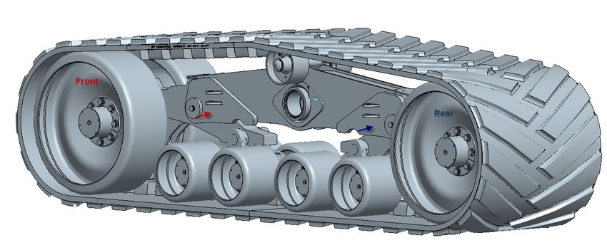
This page intentionally left blank

CPB-515 Operation and Maintenance Manual – TTS 45, 70, 80,100, 110 Series (10-2017)   2
Table of Contents
1.0 FOREWORD........................................................................................................................... 4
2.0 SAFETY .................................................................................................................................. 5
   2.1 Important Safety Information............................................................................................ 5
3.0 GENERAL INFORMATION .................................................................................................... 5
   3.1 Technical Description ....................................................................................................... 5
   3.2 Track System Components .............................................................................................. 6
   3.3 Specifications and Dimensions........................................................................................ 7
   3.4 Weight Limitations ............................................................................................................ 7
   3.5 Transport Limitations ....................................................................................................... 8
   3.6 Minimum Turning Radius Limitations.............................................................................. 9
   3.7 Operational Guidelines ................................................................................................... 10
   3.8 Track Break-in Procedures ............................................................................................. 11
4.0 TRACK SYSTEM INSTALLATION ....................................................................................... 11
   4.1 Handling of the Track System ........................................................................................ 11
   4.2 Track System Installation ............................................................................................... 11
5.0 SCHEDULED MAINTENANCE ............................................................................................. 15
   5.1 General information ........................................................................................................ 15
   5.2 Lubricant Table ............................................................................................................... 15
   5.3 Maintenance Schedule .................................................................................................... 16
   5.4 Daily maintenance or every 10 working hours .............................................................. 16
   5.5 Weekly maintenance or every 50 working hours .......................................................... 17
   5.6 Monthly maintenance or every 100 working hours ....................................................... 17
   5.7 Annual maintenance or every 500 working hours ........................................................ 18
   5.8 Every 5 years or 2000 working hours ............................................................................ 18
   5.9 Off Season Storage ......................................................................................................... 18
6.0 ROUTINE MAINTENANCE ................................................................................................... 19
   6.1 Check Track Alignment................................................................................................... 19
   6.2 Track Alignment Procedure ............................................................................................ 20
   6.3 Track system inspection................................................................................................. 21
   6.4 Adjusting track tension................................................................................................... 21
   6.5 Track Removal................................................................................................................. 22
   6.6 Track Installation ............................................................................................................. 22
7.0 TROUBLESHOOTING .......................................................................................................... 23
8.0 ADDITIONAL INFORMATION .............................................................................................. 23
9.0 Warranty Certificate ............................................................................................................ 24

CPB-515 Operation and Maintenance Manual – TTS 45, 70, 80,100, 110 Series (10-2017)                                                      3
1.0 FOREWORD
This manual provides important operation and maintenance instructions to maximize the
benefits of the Camso Trailed Track System (TTS) and to ensure performance in the field
for many years to come.
Literature Information

This manual was prepared with the latest information available at the time of publication.
Read this manual carefully before operating or servicing the undercarriage(s).
The photos, illustrations, and data used in this manual were current at the time of printing,
but due to possible production changes, your undercarriage may vary slightly. Camso
reserves the right make changes to new production undercarriages as necessary without
notification.
This document must be considered as an integral part of the rubber track system, it must
always be available for reference near the machine, even in the case of sale, and until
end of life.
Should the operations and maintenance manual supplied with the track system be
damaged or missing, please see your dealer to request another copy and/or contact
Camso immediately.
Maintenance Intervals

Use the pulling machine hour meter to determine servicing intervals. Calendar intervals
are also shown and can be used instead of hour intervals. Recommended service should
always occur on the interval that occurs first.

Under extremely dusty or wet operating conditions more frequent lubrication may be
needed.

Perform service on items at multiples of the original requirement. For example, at every
annual or 250 hour service interval, also service items listed under monthly or 100 hours,
weekly or 50 hours, and daily or 10 hours.

Camso Product Identification Number

The track system PIN plates will display the model and manufacturing date and sequence
number on both LH and RH undercarriage system. If a serialized axle is also provided by
Camso, it will also have a plate installed in the center of the axle.

CPB-515 Operation and Maintenance Manual – TTS 45, 70, 80,100, 110 Series (10-2017)      4
2.0 SAFETY
2.1 Important Safety Information
Read and understand this manual, the operation manual for the equipment the
undercarriage is mounted to, and the manual for all attachments before operating,
servicing or repairing an undercarriage.
Most personal injuries occurring during equipment operation, maintenance, or repair are
caused by failure to observe basic safety rules and precautions. In most cases, an injury
can be avoided by recognizing hazardous situations before an injury occurs.
A person must be alert to potential hazards. This person should also have the necessary
training, skills and tools to perform these functions properly.
Improper operation and maintenance of this product can be hazardous and may result in
injury or death.
Do not perform any lubrication, maintenance or repair on this product, until you have read
and understood this Operators manual.
Safety precautions and warnings are provided in this manual. If these hazard warnings
are not heeded, bodily injury or death could occur to you or to other persons.
Not every possible circumstance that might involve a potential hazard can be anticipated.
The warnings in this publication are not all inclusive. If a tool, procedure, work method or
operating technique that is not specifically recommended by Camso is used, you must
satisfy yourself that it is safe for you and for others.
You must also make sure that the product will not be damaged or be made unsafe by the
operation, lubrication, maintenance or repair procedures that you choose. The
information, specifications, and illustrations in this publication are on the basis of
information that was available at time of printing.

3.0 GENERAL INFORMATION
3.1 Technical Description
The Camso TTS allows machines to move on muddy and soft soils which have limited
carrying capacity. The wide supporting surface of the track system also reduces soil
compaction.
Camso track systems are mounted on an axle frame. Certain equipment requires a
special axle to be installed prior to track system installation. Please contact your dealer
for more information.
Camso track systems are designed to maximize the performance and productivity of your
pull-behind applications with:
•   Even weight distribution to easily and safely handle uneven terrain
•   Excellent flotation to minimize soil disturbance (40 - 70% ground pressure reduction vs. tires)
•   Maximum reliability to assure you get the job done anytime, anywhere

CPB-515 Operation and Maintenance Manual – TTS 45, 70, 80,100, 110 Series (10-2017)             5
TTS uses Camso rubber tracks, specifically designed for pull-behind applications to
provide:
• Reduced vibration during transport
• Lower turning resistance
• Minimal soil disturbance
• Long life
The patented undercarriage design incorporates independent movement of the midrollers
both front-rear and side-side delivering:
• Even weight distribution, allowing tracks to follow ground contours
• A smooth ride over rough terrain
• Reduced point loads increasing longevity of the undercarriage and implement
components
Besides the above listed characteristics, Camso rubber track systems introduce other
advantages:
Reduced power absorption on soft soils
Minimal possibility of rubber track de-tracking from the undercarriage
Adequate roading speed
Limited soil damage, soil even during end of field maneuvers
Reduced risk of self-sinking in the mud in case of slipping
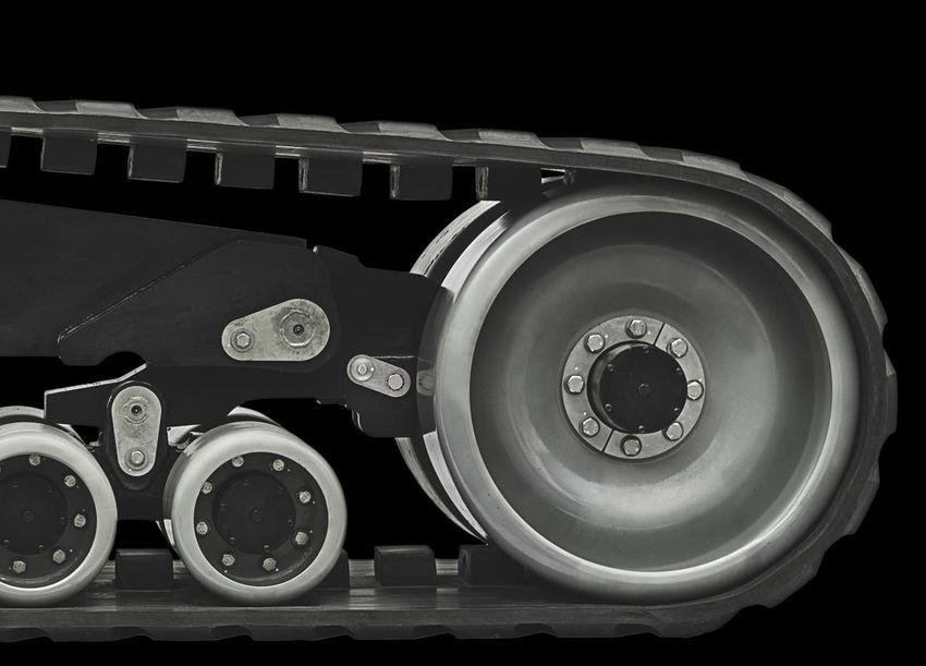
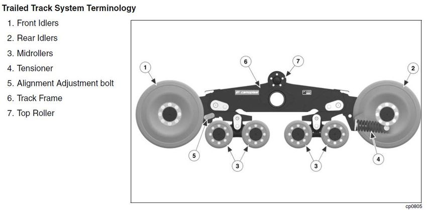
3.2 Track System Components
CPB-515 Operation and Maintenance Manual – TTS 45, 70, 80,100, 110 Series (10-2017) 6Frame
The main frame consists of a weldment which hangs the front and rear link arms. The
front alignment yoke and rear tension link are cast members, allowing for close tolerance
machining and structural rigidity.
Axles
Front and rear axles are machined from the yoke castings, allowing for dimensional
stability and few moving parts. They feature oil bath hubs mounted on tapered bearings
and mechanical seals for extreme working conditions. Each hub has its own oil reservoir
with access port for maintenance and checking oil levels.
Idlers and Midrollers
The idlers have the function of guiding the rubber track by acting on the lateral surfaces of
the guide lugs. Inner sides of idlers are subject to wear, but can be rotated to extend life.
The midrollers distribute the majority of the machine weight to the ground. They are
mounted on pivoting arms connected to the frame reducing vibration and shock loads.
Tensioning system
The tensioning system is located between the 2 rear idlers. The tension force is provided
by a mechanical spring mechanism. Track tension is provided by the spring and does not
need adjustment during operation and changing field conditions. Provisions are made to
compress the spring allowing for removal of idlers and track assemblies during
maintenance and servicing.
Rubber track
The rubber tracks are manufactured with high quality rubber and high strength steel
cabling inside for superior durability and reliability. The tread layout ensures good
flotation, excellent life, and self-cleaning characteristics.
3.3 Specifications and Dimensions
3.4 Weight Limitations
Ground # Bogie
Overall Overall Capacity -
Track Width Contact - Axles
TTS Models Height Length Per Pair
Per Pair Per UC
(in) (in) (in) (sq-in) (lbs)
45 Series
45-1814 18.0 36.1 103.5 2426 2 45,000
70 Series
70-2516 25.0 36.1 103.5 3370 2 70,000
70-3011 30.0 36.1 103.5 4044 2 70,000
70-3611 36.0 36.1 103.5 4853 2 70,000
80 Series
80-3013 30.0 40.3 136.2 6006 4 80,000
100 Series
100-3613 36.0 40.3 136.2 7207 4 100,000
110-3614 36.0 40.3 147.4 8014 4 110,000Camso track systems are limited to operating weights as listed in the table below. Do not
exceed these weight limitations or track system damage or component failure may result.
Total Scale Weight Capacity/set
Series
Kg Lbs
45 20,400 45,000
70 31,750 70,000
80 36,300 80,000
100 45,350 100,000
110 49,885 110,000
WARNING
Exceeding maximum weight capacity may result in equipment and
property damage, injury, death and void warranty coverage
3.5 Transport Limitations
Camso track systems are designed for field use and field operational speeds. High speed
transport, especially with loaded implements, is not recommended and may result in track
damage due to heat. If extended transport is required between operating locations, the
following speed and duration limits should be observed:
Operating Transport Speed Transport Duration
Condition (Maximum) (Maximum)
Empty 15 mph (24 kph) 30 min.
Loaded 10 mph (16 kph) 15 min.
WARNING
Exceeding speed limitations may result in equipment and property
damage, injury, death and void warranty coverage.
CPB-515 Operation and Maintenance Manual – TTS 45, 70, 80,100, 110 Series (10-2017) 8If additional distances are required, a 30 minute cool down period is recommended before
transport is resumed. Absolute speed and duration levels may vary, depending on system
type and ambient conditions. Limitations as listed, help avoid system heat buildup that
could cause reduction in track life.
3.6 Minimum Turning Radius Limitations
Camso track systems operate best when running straight or in gentle turns. If a track
system is pivot or spot turned, the opportunity exists for soil and dirt to be ingested into
the system. Even though TTS has a tension recoil system, if that tension recoil is
exceeded, high loads in the frame and track can be generated which may cause track or
system damage, Camso recommends that minimum turning radius limits be strictly
observed, both in the field, and also on hard ground or pavement, to avoid high stresses
due to debris ingestion, potential untracking situations, high twisting and side loads, and
significant ground scrubbing of the track treads, especially if such a turn is attempted with
fully loaded or folded systems.
Operating
Minimum Turning Radius
Condition
Field or Road 3 x the overall length of the tractor + implement
CPB-515 Operation and Maintenance Manual – TTS 45, 70, 80,100, 110 Series (10-2017) 93.7 Operational Guidelines
Any application differing from the ones prescribed in this manual are to be considered
improper and potentially dangerous.
Correct track tension is required for best performance and track life.
Camso TTS can work in extreme conditions: for operator and machine safety, be sure
to know your surroundings.
Camso TTS is free to pivot around the main axle following ground contours. During
transition over uneven ground terrain, check for interferences and move slowly to
avoid over oscillating the undercarriage.
Overall width and height of machine/equipment with Camso TTS could differ from the
original width and height with tires. Be sure to know actual machine height and width
as well as width restrictions prior to operation.
Cross large ground irregularities with suitable speed reduction and/or proper incidence
angle. In particular, when high, sharp bumps are crossed move forward slowly to avoid
shocks on the machine.
Camso TTS does not damage standard road-bed constructions. Operators must know
and respect road traffic laws.
Rubber tracks have not been designed for extended use on the road. Camso is not
responsible for track and system damage resulting for extended road use. Long road
periods and/or roading at higher than recommended maximum speeds may cause
premature wear or failure of the track or wheels. To reduce damage during roading
decrease overall machine weight and decrease machine speed, see “Transport
Limitations” section for further information.
Long runs on side slopes increase the wear on the side of guide lugs and idlers.
Keep material out of the undercarriage. Inspect undercarriage daily and remove any
material as necessary. In some conditions inspect more frequently.
If a machine becomes stuck, clear away as much material from the undercarriage as
possible prior to pulling the machine out.
Avoid short turning radius turns and operation(s) especially when loaded. Spot turning
creates debris ingestion and can also induce high torque loading in the system.
Configure drawbar and hitch correctly during field operation(s).
Use caution when operating track systems in loose, flowing material. Loose material
can become trapped between track and idlers, resulting in track damage.
Keep material out of the undercarriage. This may require scraping material out of tight
places and in some conditions require frequent inspection and cleaning
CPB-515 Operation and Maintenance Manual – TTS 45, 70, 80,100, 110 Series (10-2017) 103.8 Track Break-in Procedures
Guide lug wear is reduced when correct break-in procedures are followed. During the
break-in period, rolling components undergo a polishing-in process to achieve a smooth
steel to rubber interface with the guide lug. Rubber uses dust and dirt as a dry lubricant
during break-in and operation to minimize heat and reduce rubber stickiness. New tracks
should be exposed to dry and dusty soil conditions as soon as possible. Operation
without dust or soil in the system, especially during high speed roading, generates
high levels of damaging heat. If roading must be done, a dry lubricant such as soil, talc,
graphite, oil dry or cat litter should be applied to the guide lugs periodically during roading
until field operation resumes.
IMPORTANT: NEW SYSTEMS REQUIRING EXTENDED TRANSPORT
SHOULD BE CARRIED ON A FLAT BED AND NOT ROADED. DO NOT
ROAD A NEW SYSTEM WITHOUT FIRST CHECKING ALIGNMENT AND
INTRODUCING THE TRACKS TO DIRT OR DRY LUBRICANT
4.0 TRACK SYSTEM INSTALLATION
The Camso track systems are mounted on an axle frame. Certain equipment requires a
special axle to be installed prior to track system installation. Contact your dealer for more
information and to determine if the track system can be installed on your implement.
4.1 Handling of the Track System
The track systems can be handled by fork lifts lifting the machine from the base or by
hoists using textile bands.
WARNING
Danger of crushing. Use suitable lifting devices (capacity at least 9000 lbs
(4100Kg)), wear safety equipment and observe the safety rules.
If using a fork lift use for handling operations, be careful not to damage the
rubber track. Metal chains or cables are not recommended
4.2 Track System Installation
1. Clean the implement thoroughly before proceeding with the installation. Removal
of dirt and debris makes access to the frame and attaching fasteners easier.
2. Move the implement to a hard, level surface to ensure a stable work area to
support the implement during the track system installation.
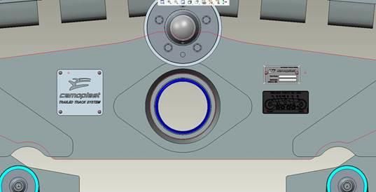
CPB-515 Operation and Maintenance Manual – TTS 45, 70, 80,100, 110 Series (10-2017) 11Serial # Plate
IMPORTANT: Locate the identification tags, as shown above, on both undercarriages,
and record the model number and serial numbers on warranty certificate for your records.
3. Raise and support implement such that the rear tires are just off the ground.
IMPORTANT
Safety of the installation depends on the right operation in lifting
and supporting the machine. Check the work area thoroughly and
work in a level area. Respect safe operating practices, operate in
conditions of enough light. Make sure the free spaces of the work
area are suitable for the dimensions of the parts to be handled and
for the lifting equipment maneuvers. Be careful: risk of injury.
4. Remove the tire and rim assemblies.
5. Remove the axle and hub assemblies from the implement frame (as required).
6. Install track fitment axle. For two axle midroller track systems, make sure the
stabilizer brackets on the axle are facing to the front of the implement. Tighten
mounting hardware.
WARNING
Danger of crushing. Use suitable lifting devices (capacity at least
9000 lbs (4100Kg)), wear safety equipment and observe the safety
rules.
In case of fork lift use for handling operations, be careful not to
damage the rubber track. Metal chains or cables are not
recommended.
CPB-515 Operation and Maintenance Manual – TTS 45, 70, 80,100, 110 Series (10-2017) 12IMPORTANT
Should a motorized lifting device be used, assistance on ground
during operation of handling, coupling and assembly is needed.
Do not stand between lifting device and axle assembly when
mounting axles to implement. Be careful: risk of injury.
Grease this
surface
7. Lightly grease machined surface of center pivot pin and insert into the receiver end
of the axle. Rotate the pin to align the rear mounting hole in the receiver pin.
Install the bolt and locknut provided with the kit. Tighten pin bolt.
8. Install the inner thrust washer against the axle pin flange.
9. Apply a light amount of grease to the center pivot pin.
10. Slide the undercarriage onto the axle pin. NOTE: Care must be exercised to avoid
damage to the lip seals on the center bore of the undercarriage assemblies during
installation. Using a fork truck, lift the undercarriage assembly onto the center pivot
pin.
CPB-515 Operation and Maintenance Manual – TTS 45, 70, 80,100, 110 Series (10-2017) 13WARNING
Make sure undercarriage is installed with track tensioner assembly
(spring) positioned to the rear of implement. DO NOT install the
track system with the tensioner positioned to the front of the
implement.
11. Install outer thrust washer, retaining cap and retainer cap bolts & washers. Torque
retainer bolts to 320 N-m +/- 64 N-m (236 ft-lbs +/- 47 ft-lbs)
12. Repeat steps 7 through 11 for the other of the axle assembly.
13. Remove jack stands and/or supports and lower implement to the ground.
14. Install the stabilizer bars (if not required skip to step 15) to a no pre-load condition.
Some slight play should be present at the rod ends. In special cases, some
adjustment to the stabilizer bars may be required to achieve the desired front to
rear parallelism dimension
a) For 2 axle midroller systems, attach the two, front stabilizer bars to the
mounting brackets on the axle and the brackets on undercarriage frame with
the hardware provided in the kit.
b) For 4 midroller axle track systems, attach the two, front stabilizer bars and two,
rear stabilizer bars to the mounting brackets on the axle and the brackets on
undercarriage frame with the hardware provided in the kit.
c) Torque turnbuckle jamb nuts to 672 N-m +/- 48 N-m.
15. Check and re-torque all wheel lug bolts as follows:
Wheel bolt diameter Torque (N-m) Torque (ft-lb)
M16 320 +/- 64 236 +/- 47
M20 620 +/- 124 457 +/- 91
CPB-515 Operation and Maintenance Manual – TTS 45, 70, 80,100, 110 Series (10-2017) 145.0 SCHEDULED MAINTENANCE
5.1 General information
Three factors: proper use, regular inspections, and maintenance are essential to ensure proper
performance and reliability of your Camso TTS track system.
It is strongly suggested to respect the recommended maintenance and inspection schedule in this
section for best track system life, proper performance, and reduced downtime.
Before any operation, clean all debris and material from the track system and make a general
analysis of the machine condition. Pay attention to components subject to wear such as rubber
parts: the quick identification of unusual wear, particularly of the track. Identifying and resolving
issues early reduces downtime and operating costs.
IMPORTANT
Routine and extra maintenance must be performed by qualified and
authorized personnel.
Before starting any kind of operation on the machine, disconnect the
transmission, stop the engine, set on the emergency brake, remove
the key and allow machine to stop completely and cool.
Make sure that mobile parts with safe fixed positioning are locked and
the tools used for maintenance are suitable for the type of service
Camso is not responsible for direct or indirect damages occurred to
people or things due to tampering, removal or modification of the
safety devices, or caused by modifications of the machine without any
previous authorization.
5.2 Lubricant Table
Use and description Location Viscosity grade
Grease for heavy Carrier Axle hubs/bearings
NLGI GC-LB
mechanical components and frame pivot joints
Idlers and Midroller Hubs 10W30 Universal
Oil Bath Reservoirs
and Midroller axle pivots Transmission / Hydraulic Oil
CPB-515 Operation and Maintenance Manual – TTS 45, 70, 80,100, 110 Series (10-2017) 155.3 Maintenance Schedule
Daily Weekly Monthly Annual 5 years or
Task or 10h or 50h or 100h or 500hr 2000hr
Inspect and clean track system X
Inspect track condition X
Check track alignment X
Inspect for oil leaks on idler,
midroller hubs and pivot axles
X
Grease undercarriage and track
system pivot points
X
Check track tension X
Re-torque wheels X
Repack carrier roller bearings X
Replace hub and pivot oil and set
wheel bearing rolling torque
X
5.4 Daily maintenance or every 10 working hours
1. Clean and remove debris from track system. Material build-up on track system
components can lead to excessive wear and premature failure.
2. Track system inspection. Walk around the machine inspecting each track system
and axle assembly. Identifying and resolving issues early is key to improving track
system life and decreasing operating expenses. See “Track System Inspection” in
the Routine maintenance section for more information.
3. Check rubber track alignment daily by inspecting the guide lugs. If excessive wear
or chunking of the guide lug is occurring, track alignment may need to be adjusted.
For additional information, refer to the “Track Alignment Procedure” section.
4. Inspect idler, midroller and midroller pivot axles for leaks. If any are noted, check
oil level of the hub to be sure oil is up to the fill hole when on a level surface.
CPB-515 Operation and Maintenance Manual – TTS 45, 70, 80,100, 110 Series (10-2017) 165.5 Weekly maintenance or every 50 working hours
1. Grease upper carrier hubs, undercarriage and track system pivot points.
#1 Tandem pin - front
#2 Bogie pin - front tandem
#3 Main central pin
#4 Bogie pin - rear tandem
#5 Carrier Roller – LH (if equipped)
#6 Carrier Roller – RH (if equipped)
#7 Tandem pins - rear
#8 Tension link pin
5.6 Monthly maintenance or every 100 working hours
1. Check track tension. Refer to chart below for recommended setting. Refer to
“Adjusting track tension” for additional information. No tension adjustment is
required if spring module is functioning properly.
Tensioner
TTS Series Spring Setting
Type
45/70/80/100/110 Spring No preload-onset of compression less one turn
2. Verify wheel bolt torque (always torque after wheel removal regardless of hrs.)
Wheel bolt
Torque (N-m) Torque (ft-lb)
size
M16 320 +/- 64 236 +/- 47
M20 620 +/- 124 457 +/- 91
CPB-515 Operation and Maintenance Manual – TTS 45, 70, 80,100, 110 Series (10-2017) 173. Verify turnbuckle jamb nut torque. Tighten as required to 670 Nm +/- 65 Nm
5.7 Annual maintenance or every 500 working hours
1. Repack carrier roller wheel bearings (item 6) (if equipped).
Carrier Roller Spanner Nut Size Torque (N-m)* Torque (ft-lb)*
N-06 10 +/- 2 7.4 +/- 1.5
* Spanner nut tool 2P-0022 is available from your Camso dealer
5.8 Every 5 years or 2000 working hours
1. Drain and replace idler, midroller, and midroller pivot reservoirs.
2. Oil level should reach to lower level of fill plug with unit parked on level surface.
5.9 Off Season Storage
1. For optimum life, TTS tracks should be stored indoors, in dry environment with
a temperature between 5° and 25° C (40-77F). The tracks should not be
exposed to direct sunlight or heat. No petrochemicals and related vapors, no
electrical devices producing ozone should be placed in the same area.
2. Should it be necessary to disassemble the tracks from the undercarriage, lay
them on the ground on one edge avoiding bending radius less than 30 in.(750
mm). Do not lay the rubber components on dirty surfaces contaminated by oil,
grease or other chemical products
CPB-515 Operation and Maintenance Manual – TTS 45, 70, 80,100, 110 Series (10-2017) 183. Do not paint rubber components.
6.0 ROUTINE MAINTENANCE
6.1 Check Track Alignment
1. Install the stabilizer bars/turnbuckle assemblies to a “no” pre-load condition.
Turnbuckle jamb nut torque is 670 Nm +/- 65 Nm.Some play should be present
at the rod ends. Make sure to unscrew the lock nut on the turnbuckle prior to
adjusting the bars to the needed length.
2. Once installed, measure the inside distance front and rear on the mainframes
as noted below. Undercarriages must be parallel to within 6mm (0.25 in.). A
suitable location for measurement is noted by arrows below the turnbuckle eyes
in the diagram below.
3. Prior to checking track alignment the implement should be empty and spring
tensioning mechanism with no pre-load.
4. Pull the implement on a flat surface for a suitable time frame, allowing the belts
to relax and move freely on the undercarriage rollers.
5. Drive in a straight line for roughly 200 ft and coast the tractor to a stop. Place
the tractor in PARK and apply the emergency brake. Do not apply braking
action during this process as sudden stops can affect track position during the
alignment process.
CPB-515 Operation and Maintenance Manual – TTS 45, 70, 80,100, 110 Series (10-2017) 196. Using a ¼” x 4” x 8” shim (A) slide between the front midroller and guide lugs
(B). Bridge guide lugs with the shim maintaining pressure on 2 lugs minimum.
7. If the shim fits freely between the lugs and midroller on both sides of the
undercarriage the alignment is correct. It the shim binds and does not fit
between the midrollers/guide lugs track adjustment is necessary.
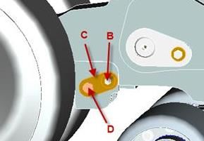
6.2 Track Alignment Procedure
1. Remove the retainer lock plate cap screws (b) and lock plate (c) from the inboard &
outboard sides of the track needing adjustment.
2. Loosen cap screw (d) counterclockwise 1-1.5 turns on the side of the
undercarriage you want the track to move towards.
3. Tighten the special cap screw on the opposite side to specification. (Cap screw
torque is 300 N-m (221 ft-lb). Tighten cap screw loosened in step 2 to the same
specification. Note: A single full turn is the standard increment during
adjustment. Lessen this amount as final adjustment is approached.
4. Recheck track alignment and adjust until suitable clearance is obtained on both
sides of the guide lugs. Note: Lock plates are reversible for double the index
increments. If needed, increase torque on the special cap screw slightly
allowing advancement to a suitable lock plate position.
CPB-515 Operation and Maintenance Manual – TTS 45, 70, 80,100, 110 Series (10-2017) 205. When alignment is complete reinstall the lock plates and tighten cap screws to
their required torque specification of 130 N-m (95 lb-ft).
6.3 Track system inspection
Track System
Inspect track system for material build-up on frames and wheels. Clean material from
undercarriage.
Idlers and midrollers
Check the general condition of the idlers and midrollers, in particular on inner guide
surface of the wheels. Excessive wear in these areas can be caused by track alignment
issue, debris ingestion or continuous hillside work.
Rubber track guide lugs
Guide lugs keep the track on the track system. Proper alignment of the track is essential
to improving overall life and decreasing operating costs. If track is misaligned or operating
on side slope, guide lug wear or damage may occur. Also guide lug damage may occur if
proper break-in procedures are not followed or system is operated outside the maximum
speed recommendations listed in this manual. Monitoring guide lugs condition will alert
the operator to an issue and generally if corrected early prior to loss of performance or
durability.
Track carcass
Inspect track surface to remove imbedded stones or debris. This contamination can work
its way into the track and damage the steel cable.
Steel wire may come out from the track carcass without affecting the performance of the
track. Remove loose wires by cutting them at the rubber surface.
Track tread
Muddy soils usually cause limited wear, while roading long distances can bring about
accelerated tread wear. Due to the crown of the road, and deflection in the system, the
tread closest to the machine will tend to wear faster than the tread on the outer portion of
the track. Adhere to speed and weight limitations published in this document.
6.4 Adjusting track tension
Tension is pre-set at the factory and requires no adjustment during operation. Provision is
made to detension the track system allowing for removal of the rubber track.
CPB-515 Operation and Maintenance Manual – TTS 45, 70, 80,100, 110 Series (10-2017) 216.5 Track Removal
1. Place the undercarriage on a level surface and loosen the nuts on the idler wheels.
Undercarriage may not need removal from the implement to be worked on.
2. Locate the tension module located between the rear idlers. Remove the 2 bolts
fastening the rotation lock to the frame. Remove the lock.
3. Turn the tension screw clockwise to compress the spring which loosens the track.
Turn the screw until it bottoms out on the stop. Do not force the spring past this
point.
4. Using a suitable lifting device raise the undercarriage until there is clearance
between the wheels and track.
5. Remove the wheel bolts and torque plate castings. Note: idler wheels weigh
90kg (200lbs) and will roll easily on a firm surface. Place a stop under
removed wheels to stop rolling and potential injury.
6. Remove the inner idler wheel.
7. Using a suitable lifting device, lift the track slightly near the front and rear idlers,
pulling slightly away and back from the undercarriage to remove the track. Note: If
using a forklift or other steel lifting device, ensure the tines or lifting surface
does not have sharp edges or track damage may occur.
8. Lift the track up and away from the undercarriage, placing in a suitable location for
installation.
6.6 Track Installation
9. Raise the undercarriage roughly 12 in. from the ground to allow for the lower
surface of the belt to slide underneath.
10. Lift the track and install on the top carrier rollers. Push the bottom of the track
under the midrollers aligning with the front and rear idlers.
11. Install the idler wheels removed previously, ensuring the guide lugs are positioned
properly between the midrollers and idlers.
12. Lower the undercarriage assembly to the ground. Turn the tensioning screw
counterclockwise to extend the tensioning spring. The screw should be retracted
until there is no preload on the spring. Thread the screw in to the onset of
compression and back off ½ turn.
13. Install tensioning screw rotation lock and torque retainer bolts to 122 N-m (90 lb-ft).
CPB-515 Operation and Maintenance Manual – TTS 45, 70, 80,100, 110 Series (10-2017) 227.0 TROUBLESHOOTING
Problem Possible cause Solution
Uneven tread wear High amount of roading Swap tracks side to side
Splits/opening on the High amount of roading or Swap tracks side to side,
side or top of tread overheat of tread replace tracks if necessary
Align track, see “Track
Track not aligned properly Alignment Adjustment”
section
Chunking on guide Operate in dry dusty
lug sides Improper break-in of track conditions, see “Track
Break-in” section.
Side slope operation Contact Dealer
Material or workmanship defect
Contact Dealer
Breakaway of track (clean separation)
guide lugs Debris/material ingestion into Clean material off of drive
track system. (jagged wheel
separation)
Verify position of track
Correct tensioning not Bolt fully retracted with no
detensioning bolt at rear idler
possible preload on spring applied
assembly
High temperature of Bearing failure Replace damaged bearing
idler or roller axle hub Check oil level in reservoir
Lack of lubricant
Noise from idler or service
Bearing failure Replace damaged bearing
roller axle hub
Mud/dirt build up on Operation in muddy, wet, or Clean mud/dirt regularly to
idlers/midrollers sticky soil types prevent track damage.
System dog tracking Alignment adjustment incorrect. Adjust alignment per
or problems with track Undercarriages parallelism is procedures. Otherwise,
alignment out of tolerance contact your Dealer
8.0 ADDITIONAL INFORMATION
Additional information on Camso track systems, tracks, and our other products may be
found at http://www.Camso.co.
For any questions or corrections regarding this manual, please email us at
Ag.Productsupport@Camso.co . You can also contact our Customer Service Desk @
317-671-7327 or 1-844-226-7624.
Please include the manual publication number and edition as found in the footer
CPB-515 Operation and Maintenance Manual – TTS 45, 70, 80,100, 110 Series (10-2017) 239.0 Warranty Certificate CPB-515 Operation and Maintenance Manual – TTS 45, 70, 80,100, 110 Series (10-2017) 24
You can also read