Evaporative Emission Control Technologies for Gasoline Powered Vehicles - Manufacturers of Emission Controls Association
←
→
Page content transcription
If your browser does not render page correctly, please read the page content below
Evaporative Emission Control Technologies
     for Gasoline Powered Vehicles

                           December 2010

         Manufacturers of Emission Controls Association
           2020 N. 14th St. * Suite 220 * Arlington, VA 22201
                              www.meca.org
                           www.dieselretrofit.org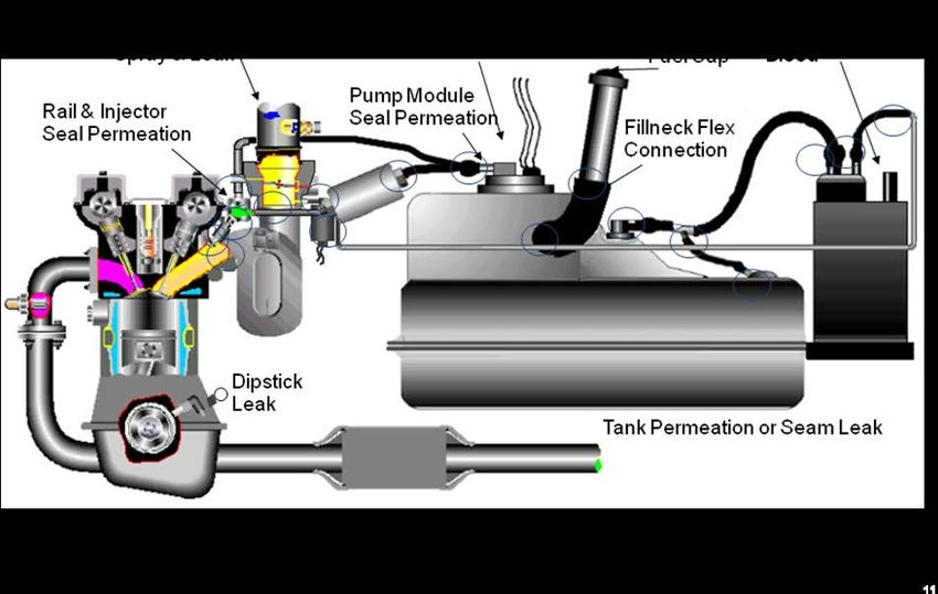
TABLE OF CONTENTS

Executive Summary ........................................................................................................................ 1

1.0 Introduction ............................................................................................................................... 3

2.0 Current Evaporative Emissions Regulations in the U.S. .......................................................... 5
       2.1 ARB’s Proposed LEV III Evaporative Emissions Requirements ................................. 7
       2.2 Test Methods for Measuring Evaporative Emissions ................................................... 9

3.0 Technologies to Control Evaporative Emissions .................................................................... 10
       3.1 Permeation Controls.................................................................................................... 11
       3.2 Carbon Canisters ......................................................................................................... 12
       3.3 Activated Carbon ........................................................................................................ 14
       3.4 Air Intake Systems (AIS) ............................................................................................ 16
       3.5 On-Board Refueling Vapor Recovery ........................................................................ 17

4.0 On-Board Diagnostic Requirements ....................................................................................... 18

5.0 Conclusions ............................................................................................................................. 18

6.0 References ............................................................................................................................... 18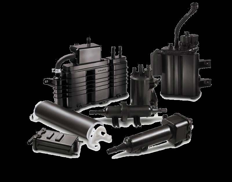
LIST OF FIGURES

Figure 1: Emissions Contributions for PZEV and LEV II Vehicles ............................................... 5
Figure 2. CARB LEV II and PZEV Evaporative Requirements ................................................... 7
Figure 3. Test set-up for a bleed emissions or mini-rig test.......................................................... 10
Figure 4. Fuel system with emission control technology ............................................................. 11
Figure 5. Examples of evaporative carbon canisters .................................................................... 12
Figure 6. Inside of EVAP canister ................................................................................................ 13
Figure 7. Canister bleed emissions with and without a scrubber .................................................. 14
Figure 8. Pore size depiction in activated carbon particle ........................................................... 15
Figure 9. Examples of extruded carbon honeycombs .................................................................. 16
Figure 10. Examples of carbon AIS systems ............................................................................... 16
Figure 11. Examples of carbon AIS systems ............................................................................... 17
Figure 12. Air Induction System performance on 4 and 8 cyl. engine ........................................ 17

LIST OF TABLES

Table I:      CARB LEV II Evaporative Emission Standards .......................................................... 6
Table II:     U.S. EPA Tier II Evaporative Emission Standards ....................................................... 6
Table III:    Option 1 of ARB’s Proposed LEV III Evaporative Standards ..................................... 8
Table IV:     Option 2 of ARB’s Proposed LEV III Evaporative Standards ...................................... 8
Executive Summary

         Evaporative emission control technology was the first to be used on passenger vehicles as
a way to control smog forming hydrocarbons in the early 1960’s. Evaporative emissions from
motor vehicles constitute about half of the reactive organic gas (ROG) inventory in California 1
and nearly 40% in the Northeastern United States. Ozone is considered to be a respiratory
irritant harmful to humans and plants and is regulated by the U.S. EPA which sets a National
Ambient Air Quality Standard (NAAQS) for ozone concentration. Areas that are out of
attainment or experience concentrations above this ozone concentration, like California, regulate
evaporative emissions to reduce ground-level ozone. In addition to the negative health effects of
ground level ozone, it is also a greenhouse gas.

        Evaporative emissions are broken down into five primary sources; diurnal, running loss,
hot soak, permeation and refueling. The magnitude of the relative components depends greatly
on the engine design, fuel delivery and application. A brief description of the major types of
evaporative emissions is given below.

       Diurnal emissions result from the evaporation of gasoline due to temperature fluctuation
       during the day and night.

       Running loss emissions represent gasoline that is vaporized from the engine and fuel
       system while in operation.

       Hot Soak emissions occur during the first hour that the vehicle is parked after normal
       operation.

       Permeation occurs continuously once the polymer components of the fuel system become
       saturated with fuel.

       Refueling emissions occur as gasoline is pumped into the tank displacing the gasoline
       rich vapor.

               The function of the automobile evaporative emission control system is to block or
capture the above sources of vaporized hydrocarbons and prevent their release into the
atmosphere. There are varying levels of complexity and efficacy of these controls with the most
advanced systems equipped on partial zero emission vehicles being certified to California’s
PZEV standard under the state’s LEV II emission standards.

       Companies that manufacture evaporative emission controls have responded to the
challenge of reducing VOC emissions from gasoline powered vehicles. Through their efforts, a
wide range of cost-effective technologies have been developed to block HC emissions via the
above mechanisms. Manufacturers of Emission Controls Association (MECA) member
companies, together with engine manufacturers, have worked together to meet California’s
PZEV requirements on over 50 light-duty vehicles and employed evaporative canisters on
motorcycles and marine engines.

                                                1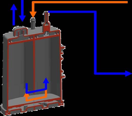
Interest in evaporative emissions control has grown considerably in recent years around
the world. MECA is engaged with California on their LEV III regulation that proposes to extend
the most advanced evaporative controls across the entire on-road, light and medium-duty vehicle
fleet. This document has been prepared to supplement information already made available by
MECA on emission control technologies and provides an overview of the types of technologies
being developed for new gasoline fueled cars and trucks.

        Today’s cleanest gasoline vehicles, certified to California’s PZEV emission limits require
near zero evaporative emissions and include additional technologies such as canister scrubbers to
virtually eliminate bleed emissions from the carbon canisters during periods of low purge. Some
vehicles also incorporate carbon based air-intake HC traps to prevent engine breathing losses
from escaping through the intake manifold and air induction system (AIS) after the engine is shut
off.

       Today, viable emission control technologies exist to reduce fuel system based HC
evaporative emissions from all types of spark-ignited engines including small handheld
equipment up to large spark-ignited (LSI) vehicles. Applications include marine and recreational
off-road vehicles. The major technologies that control permeation emissions include:

       •   Fuel tanks made of low permeation polymers
       •   Multilayer co-extruded hoses
       •   Low permeation seals and gaskets

Technologies designed to control diurnal, hot soak and refueling HC emissions include:

       •   Advanced carbon canisters
       •   High working capacity activated carbon
       •   Honeycomb carbons scrubbers
       •   Air induction system (AIS) HC traps

        The most stringent evaporative emission control regulations are enforced in the United
States. Vehicles certified to California’s PZEV low emission vehicle standards must
demonstrate near zero evaporative emissions from the fuel system at 0.054 g/test using a rig test
of a vehicle’s fuel system. The California Air Resources Board (CARB) is proposing to extend
these requirements across the entire light-duty and medium-duty passenger vehicle fleet
(
1.0 Introduction

        Evaporative emissions from gasoline powered vehicles consist of volatile organic
compounds (VOCs), or hydrocarbons, released from the fuel system, rubber and other plastic
components of the vehicle, such as tires, plastic interior and exterior trim, carpeting etc. This
paper will focus on the hydrocarbon vapors emitted from the fuel system as these represent the
major sources of evaporative emissions from mobile vehicles and equipment. This paper will
further focus on fuel-related evaporative emissions from light-duty vehicles. Some of the same
types of technologies that are discussed here for passenger cars have been successfully applied to
other spark-ignited off-road vehicles and equipment and will not be covered here. A more
detailed discussion of regulations and evaporative control technologies in these applications can
be found in MECA’s white papers specific to those applications available at www.meca.org.

        Evaporative emissions from motor vehicles constitute about half of the reactive organic
gas (ROG) inventory in California 1 and nearly 40% in the Northeastern United States.
Evaporative emissions depend on ambient temperatures and the vapor pressure of the fuel
supply. VOCs and other hydrocarbons (HC), such as those emitted from the tailpipe of motor
vehicles, react with NOx in the presence of sunlight to form photochemical smog which is the
primary component of ground level ozone. Ozone is considered to be a respiratory irritant
harmful to humans and plants and is regulated by the U.S. EPA which sets a National Ambient
Air Quality Standard (NAAQS) for ozone concentration. Areas that are out of attainment or
experience concentrations above this ozone concentration, like California, regulate evaporative
emissions to reduce ground-level ozone. In addition to the negative health effects of ground
level ozone, it is also a greenhouse gas.

        Evaporative emissions are broken down into five primary sources; diurnal, running loss,
hot soak, permeation and refueling. The magnitude of the relative components depends greatly
on the engine design, fuel delivery and application.

        Diurnal emissions result from evaporation of gasoline due to temperature fluctuation
during the day and night. As the fuel tank warms during the day or while parked in the sun,
expansion of the gasoline vapor above the liquid is vented from the tank. During the night, as
the tank cools, fresh air is pulled into the tank to mix with the gasoline vapors to start the process
again the next day.

        Gasoline vapors coming from the engine and fuel system while in operation are known as
running losses. The primary source of running loss emissions in earlier passenger cars was from
the carburetor. Modern vehicles may emit small amounts of emissions from the fuel cap and
vapor canister. Most of these HCs end up being captured by the evaporative emission control
system and routed back through the intake of the engine to be consumed during combustion.

        Emissions attributed to the hot soak occur during the first hour that the vehicle is parked
after normal operation. During this time, the engine remains hot and, without convective
cooling, continues to heat the fuel system. This source is primarily attributed to carbureted
vehicles and equipment. In modern vehicles equipped with fuel injectors and carbon canisters,

                                                  3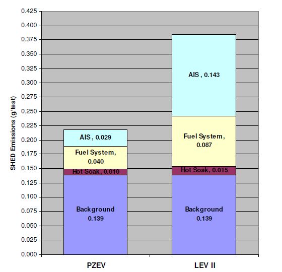
the hot soak vapors would be captured and stored until the next time the engine is running. At
this time they would be purged into the intake air of the engine and combusted.
Permeation of gasoline molecules can occur during normal operation or extended periods
of parking a vehicle. This is caused by the saturation of the plastic and rubber components of the
fuel system such as plastic fuel tanks and rubber hoses and results in relatively constant
permeation through these components. Significant advances in polymer chemistry and laminated
forming techniques have significantly reduced permeation as a source of emissions in modern
vehicles.
Refueling emissions can occur as gasoline is pumped into the tank displacing the gasoline
rich vapor causing it to be emitted into the atmosphere. In modern passenger vehicles, these
vapors are stored in the EVAP canister and purged into the intake air of the engine to be
combusted.
The function of the automobile evaporative emission control system is to block or capture
the above sources of vaporized hydrocarbons and prevent their release into the atmosphere.
There are varying levels of complexity and efficacy of these controls with the most advanced
systems equipped on partial zero emission vehicles (PZEV) being certified to California’s
tightest evaporative standard under the state’s LEV II and future LEV III emission standards.
Evaporative emission controls were the first type of emission control system on
automobiles and is often the least expensive approach to controlling VOC and HC emissions
from gasoline powered engines. In the 1960s positive crankcase ventilation systems were
introduced to capture crankcase vapors and prevent them from being vented to the atmosphere.
The technology has advanced to include carbon canisters, low permeation hoses, active purge
systems and on-board vehicle refueling (ORVR) controls. Eventually on-board diagnostic
sensors were integrated to insure proper functioning of the entire fuel evaporative control system.
Hot soak emissions were a problem in carbureted engines releasing gasoline vapors from the fuel
bowl as the temperature in the engine compartment increased after shut down. Initially air filter
assemblies were used to capture these emissions and later carbon canisters were connected with a
hose to the fuel bowl. The introduction of fuel injection greatly reduced evaporative emissions
due to hot soak and running loss as they isolated the fuel from the atmosphere at all time except
for refueling. On-board refueling vapor recovery (ORVR) systems have been required on all
passenger vehicles in the U.S. since 2000 and capture vapors emitted from the tank during
refueling in the carbon canister and later emit them into the combustion chamber during canister
purging.
Today’s cleanest gasoline vehicles, certified to California’s PZEV emission limits require
near zero evaporative emissions and include additional technologies such as canister scrubbers to
virtually eliminate bleed emissions from the carbon canisters during periods of low purge. Some
vehicles also incorporate carbon based air-intake HC traps to prevent engine breathing losses
from escaping through the intake manifold and air induction system (AIS) after the engine is shut
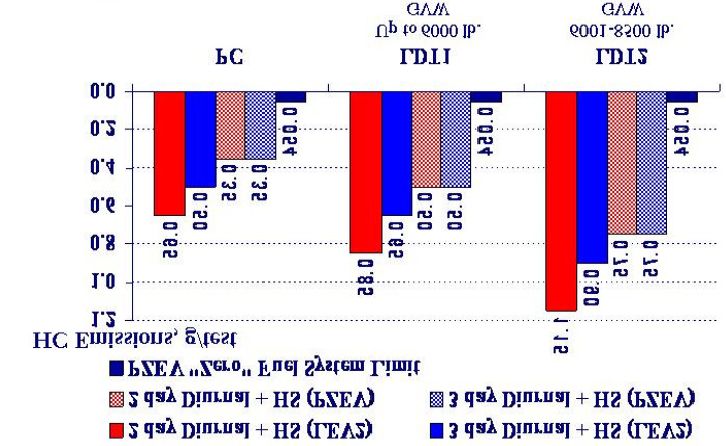
off. Figure 1 shows the benefit that advanced evaporative controls can have on the relative
amounts of evaporative emissions contributed from different parts of a vehicle. The bar chart
quantifies the mass of evaporative emissions that contribute to the SHED test measurement for a
4typical LEV II and PZEV certified vehicle. The background emissions represent the non-fuel
related evaporative emissions from carpets, rubber and plastic parts. The emissions that are
readily impacted by advanced evaporative control technology are those emitted by the air
induction system (AIS) and fuel system. Carbon AIS traps can reduce emissions by 0.10 to 0.15
g/test and incorporating canisters with auxiliary scrubbers onto a LEV II vehicle reduces tank
venting emissions by as much as 0.1 g/test. The advanced emission control technologies used on
PZEV vehicles are very effective and leave background emissions as the major contributor
(65%) to the total evaporative emissions.
Figure 1: Relative contribution to full vehicle emissions from different sources for PZEV
and LEVII certified vehicles.
After a brief review of the evaporative emission regulations in the United States, this
paper will describe the specific evaporative control system technologies in greater detail.
2.0 Current Evaporative Emission Regulations in the U.S.
California has enforced evaporative emissions on light-duty vehicles since 1970. The
current requirements under CARB’s low emission vehicle program were fully implemented in
2006 for the entire fleet. The evaporative emission standards are shown below for the three-day
diurnal-plus-hot soak test and the two-day diurnal-plus-hot-soak test. The standards are
expressed in total vehicle HC evaporative emissions and include both fuel and non-fuel vehicle
emissions. The three-day diurnal test insures that running loss emissions, high temperature hot
soak and diurnal emissions are controlled whereas the two-day diurnal test verifies that the
canister is well purged during vehicle operation. For 2001 and newer vehicles, additional testing
of the ORVR system is required to insure that refueling emissions do not exceed 0.2 g/gal. of
fuel dispensed. The standards apply to gasoline-fueled, liquefied-petroleum-gas-fueled, and
alcohol-fueled passenger cars, light-duty trucks, medium-duty vehicles, and heavy-duty vehicles.
5Included in these requirements are flexible-fuel vehicles, dual-fuel vehicles, hybrid-electric
vehicles, and zero-emission vehicles with fuel fired heaters. Table I shows the evaporative
emission limits for the current California LEV II standards.
Table I: CARB LEV II Evaporative Emission Standards
The standards were also adopted by U.S. EPA as part of their Tier II light-duty vehicle
standards with a different phase-in period. Both agencies introduced the standards in 2004 with
requirements for 40% of the fleet in California and 25% federally. California completed the
phase in by 2006 with full harmonization by both agencies in 2009 for evaporative emissions.
The fleet average evaporative limits for EPA’s Tier II standards are shown in Table II. The
evaporative emission control system standards include a useful-life requirement of 15 years or
150,000 miles, whichever comes first.
Table II: Evaporative Emission Limits under EPA’s Tier II Standards
Supplemental
3 day Diurnal + Hot Running
2 day Diurnal + Hot
Vehicle Type Model Year Soak Loss
Soak
(g/test) (g/mi)
(g/test)
LDV/LLDTs 2004 0.95 1.20 0.05
HLDTs 2004 1.20 1.50 0.05
MDPVs 2004 1.40 1.75 0.05
Federal LDV 2009 0.50 0.65 0.05
LLDT 2009 0.65 0.85 0.05
HLDT 2010 0.90 1.15 0.05
MDPV 2010 1.00 1.25 0.05
California allows manufacturers to certify to their zero-fuel evaporative standards as a
way to generate credits toward meeting the states zero-emission vehicle (ZEV) requirements.
The PZEV requirements are compared to the LEV II limits for passenger cars and light-duty
6trucks in Figure 2. In addition to tighter limits for the diurnal tests, manufacturers must also
meet a near zero (0.054 g/test) limit for the fuel system using a rig test. The EVAP test
procedures will be described in greater detail in Section 2.1.
Figure 2: CARB LEVII and PZEV Evaporative Requirements
Meeting the PZEV limits requires the use of advanced fuel and evaporative control
systems that are capable of essentially eliminating fuel-related evaporative emissions. These
advanced technologies include a pressurized and sealed fuel system such as an insulated, bladder
fuel tank, larger chambered carbon canister equipped with a bleed emissions scrubber and an
AIS carbon filter. A more detailed description of LEVII and PZEV technologies will be
provided in Section 3.0.
2.1 ARB’s Proposed Evaporative Emission Requirements for LEV III
ARB is in the final stages of finalizing their evaporative emission requirements as part of
their LEV III proposal that will be presented to the Board in April of 2011. ARB is proposing to
extend “zero” evaporative emission technology to all light-duty and medium-duty vehicles.
Phase-in of these proposed vehicle evaporative emission requirements would begin
with model year 2018 and be complete by model year 2022. The phase-in would require that
60% of the fleet is in compliance in the 2018-19 time frame ramping up to 80% compliance by
2020 to 2021 and full coverage of the fleet by 2022. To certify to the new standards ARB is also
proposing to require the use of an E10 certification fuel starting with the 2014 model
year for new vehicles. Because all gasoline fuel in California contains 10% ethanol, this will
bring certification data more in-line with real world emissions. All certifications would need to
use the E10 fuel starting in model year 2018.
7Vehicle manufacturers would have two options for evaporative emissions compliance.
The first option is to comply with the current “zero” evaporative, whole vehicle standard that
varies with vehicle weight and use the current complete fuel system rig test to confirm that the
fuel system has no more than 0.054 g/test of evaporative emissions.
Table III: Option 1 of ARB’s Proposed LEV III Evaporative Standards
The second option allows manufacturers to comply with a lower whole vehicle emissions
standard and use a new bleed emissions test protocol to confirm that the carbon canister bleed
emissions are less than or equal to 0.02 g/test for all light-duty vehicle classes and less than or
equal to 0.03 g/test for medium-duty and heavy-duty vehicle classes (Table 4). Within this
second option, manufacturers would be allowed to comply with a fleet average whole vehicle
standard within each weight class. Manufacturers will be required to report the highest value of
the 3-Day Diurnal and 2-Day Diurnal plus hot soak for a given certification test vehicle. The
test procedures for the fuel system rig test and bleed emissions test will be described in Section
2.2. Evaporative emission system certification for hybrid electric vehicles will have specific test
procedures as these vehicles can have low canister purge rates relative to non-hybrid vehicles.
Table IV: Option 2 of ARB’s Proposed LEV III Evaporative Standards
Europe and other countries around the world have implemented evaporative emission
standards on automobiles and other gasoline powered vehicles since 1983. Most of these have
followed the European standards for fuels and emission limits and will not be discussed here.
8These EURO based regulations for evaporative emissions are generally less stringent than U.S.
or California regulations. Evaporative limits have also been established for non-automotive
applications including motorcycles, small and large off-road spark-ignited engines as well as
marine engines. Although these will not be covered here, some information on evaporative
emission standards and technologies for non-automotive applications can be found in MECA’s
small engine2 and motorcycle3 white papers.
2.2 Test Methods for Measuring Evaporative Emissions
The apparatus used to evaluate the diurnal and hot soak emissions from automobiles is
known as a SHED or Sealed Housing for Evaporative Determination. To conduct the
measurements, the vehicle is driven into the chamber and the doors are sealed. The SHED is
equipped with analyzers to measure HC emissions inside the chamber at various intervals. A
flame ionization detector (FID) measures the total hydrocarbons at the beginning and end of each
test to determine emissions from the hot soak and each diurnal day. An infrared detector is used
to distinguish between fuel based HC’s and non-fuel based HCs such as those from polymers,
rubber and plastics. The two-day plus hot soak test consists of running the vehicle on a Federal
Test Procedure (FTP) drive cycle with a loaded carbon canister followed by a one-hour hot soak
at elevated temperature and monitoring over two-diurnal days. The result that is reported is the
total of the hot soak and the highest value from one of the diurnal days. The canister is pre-
loaded with a mixture of butane and nitrogen to simulate the state of the canister if the vehicle is
not driven for several days or recently refueled. The hot soak simulates parking the vehicle at
72 οF after driving. The temperature range for the diurnal day to represent a California ambient
environment consists of a soak at 65 οF followed by a 12 hour ramp up to 105 οF and a
subsequent 12 hour cool down to 65 οF. The U.S. EPA diurnal cycle consists of a temperature
cycle from 72 οF to 95 οF.
The three-day diurnal test for CARB includes an additional running loss test which
involves an FTP drive cycle performed at an ambient temperature of 105 οF. Additional
emissions measurements are taken at the filler cap and canister to make sure that the purge
system is functioning properly and emissions are contained during operation. Following the
running loss test, the vehicle emissions are measured after a one-hour hot soak at 105 οF
followed by three days of diurnal cycles as in the two-day test. The results that are reported for
the three-day diurnal test combine the emissions measured during the hot soak and the highest of
the three diurnal days.
In order to meet the PZEV emission requirements, manufacturers must demonstrate
elimination of fuel system related evaporative emissions. The zero-evaporative standard has
two components that must be tested separately. First, the whole vehicle must be tested in a
SHED for the two and three-day diurnal to show that emissions from all HC sources do not
exceed 0.35 g/test for passenger cars under LEV II and Tier 2. Larger vehicles are allowed
higher whole vehicle limits as shown in Figure 1. Second, to test only the emissions from the
fuel system components, a rig test is used. For this test, the fuel system of the vehicle is
reassembled inside the SHED and subjected to diurnal testing. The emissions from this test must
not exceed 0.054 g/test.
9The rig test requires that a support frame and the entire fuel system be assembled inside a
SHED apparatus. The assembly includes the fuel tank, fuel metering system, including injectors
and fuel vapor control system such as the canister. The testing takes over 160 days to complete
including time to age the components and a 140 day stabilization period. The actual SHED
diurnal testing takes about 1-2 weeks. The bleed emissions test or mini-rig test that ARB has
included under compliance option 2 of the LEV III proposal was suggested by MECA as a way
to insure against backsliding by de-contenting advanced canister technologies from PZEV
vehicles that might occur if only a whole vehicle test was required. Because a whole vehicle test
combines evaporative emissions from the fuel system with non-fuel related VOCs, without a
separate fuel system test, manufacturers could trade-off higher fuel related emissions for lower
non-fuel emissions to pass a higher vehicle limit. This may result in the removal of the best
available canister technologies and lead to higher overall evaporative emissions during real
world operation.
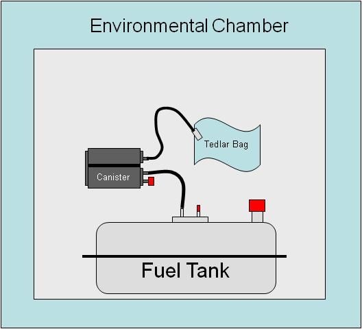
The bleed emissions test is much simpler because it only tests the critical fuel vapor
control components in a SHED apparatus.5 The components involved in the test include the fuel
tank, tank vent lines and carbon canister (Figure 3). Under this test, the canister can be aged and
prepared in under 2 weeks resulting in a total test time of only two and a half weeks. Only the
canister venting emissions are measured and included to meet the 0.02 g/test limit as proposed
for LEV III.
Figure 3: Test set-up for a bleed emissions or mini-rig test
3.0 Technologies to Control Evaporative Emissions
Evaporative emissions from vehicles can be significantly reduced by addressing the
primary sources of HC leakage from the fuel system such as permeation, diurnal, and refueling.
The technologies employed in modern fuel systems to address these mechanisms will be the
topic of this section. The sources of these emissions are better illustrated in Figure 4 which
depicts a typical fuel system.
10Figure 4: Fuel system with emission control technology. Circles identify common joints
and connectors as sources of liquid and vapor leakage.
3.1 Permeation Controls
Permeation emissions can be addressed by reducing the permeability of plastics and
polymers to gasoline in either the liquid or vapor phase. This can be accomplished through both
design and selection of materials. Reducing the number of joints and connectors in a fuel system
and the design of the fuel tank are some of the ways to reduce fuel leakage and permeation. Fuel
system design is not within the scope of this paper but we will touch briefly on materials of
construction as a way to control permeation. This is important in tanks, hoses, seals and
connectors. Although metal tanks offer the highest barrier to permeation, they add weight and
limit the shape necessary to meet stringent packaging requirements. Advanced tanks consist of
coextruded, multilayer construction with a barrier layer of ethylene vinyl alcohol and
fluoropolymers to reduce permeation. Furthermore, polymers can be treated via sulfonation or
fluorination to further reduce permeability.
Similar approaches of material selection can be applied to fuel hoses, seals, fuel caps and
gaskets used within the fuel system. The use of coextruded, low permeation polymers such as
nylon, fluoropolymers, and fluoroelastomers can be employed in fuel lines to significantly
reduce permeation emissions. Special challenges in permeation emissions and materials
compatibility have resulted since the introduction of ethanol blends in gasoline. The newest
vehicles and, in particular, Flexible Fuel Vehicles (FFV) are equipped with the lowest
permeation materials in the fuel tanks, hoses, seals and gaskets. Older vehicles and, in particular,
spark-ignited off road engines like those used in lawn equipment, marine engines, recreational
motorcycles and ATVs still use conventional fuel system materials which are not compatible
with ethanol levels above 10%. There is a concern that if this equipment and vehicles are fueled
with ethanol-gasoline blends greater than E10 they will result in significant emissions of
hydrocarbons into the atmosphere contributing to ozone formation. Furthermore these engines
11are not calibrated to operate on higher ethanol blends. The low permeation technology discussed
here is equally effective in reducing evaporative emissions from all types of gasoline powered
vehicles and equipment but require technology forcing regulations for implementation.
3.2 Carbon Canisters
One of the essential components of the evaporative emission control system is the carbon
canister. The canisters employed on automobiles, and other gasoline powered vehicles and
equipment, are similar and consist of a plastic housing containing high surface area carbon
adsorbent material. Hydrocarbon molecules are attracted to the non-polar surface of the
activated carbon and stored within the pores by physical adsorption or physisorption. Canister
filling occurs during diurnal events and refueling. Canisters come in many shapes and sizes and
are proportional to the volume of vapor generated in the fuel tank (Figure 5).
Figure 5: Examples of the shapes and sizes of EVAP canisters for on-road and off-road
applications.
Advanced canisters employ multiple chambers and specially designed carbon adsorbents to
achieve very low or zero evaporative emissions depending on the level of evaporative emission
that must be achieved. The carbon technology will be discussed in Section 3.2.1. As HC vapors
are forced out of the tank during heating or refueling, they enter the first chamber of the canister
and pass through to the second chamber (see Figure 6).
12Atmosphere
Adsorption
Desorption
Figure 6: Inside of EVAP canister without carbon adsorbent to show chambers and
adsorption/desorption process.
Canister purging occurs during engine operation. In early automotive canister designs
and more recent off-road applications such as spark-ignited marine engines which employ carbon
canisters, the purging occurs passively by the vacuum created during cooling of the tank and
fuel. The tank vacuum will pull clean ambient air through the canister causing desorption of the
hydrocarbon molecules from the carbon surfaces. The vacuum created during engine operation
pulls air through the carbon bed resulting in desorption of HCs and drawing them into the intake
of the engine. A sudden surge in HCs into the combustion chamber can result in excessive
hydrocarbons in the tailpipe. Control of the vapor concentration of the purge air stream by the
engine control system is necessary to meet both exhaust and evaporative emission standards.
Proper metering of purge flow using the purge valve and restricting vapor flow from the fuel
tank with a flow management orifice are methods that are used to prevent large HC vapor
transients from entering the intake of the engine but yet allow high gas flow during refueling
events.
Important elements of canister design used to control bleed emissions include cross-
sectional area and pressure drop. The length-to-diameter (L/D) ratio of the canister can be
optimized to increase diffusion path length while minimizing pressure drop.5 The working
capacity is another important design parameter for carbon canisters that is also affected by the
L/D ratio. Working capacity represents the amount of hydrocarbons by weight that can be
maintained within the activated carbon charge of the canister under a well defined test procedure.
In general the L/D ratio is optimized for working capacity without compromising backpressure
within the constraints of packaging. Increasing the L/D ratio of the canister increases the
13localized airflow over the carbon bed during purging resulting in more effective removal of the
adsorbed HCs.5 Carbon canisters are very effective and extremely durable control technologies
with little or no deterioration of performance over the full useful life of the vehicle.
The zero evaporative emissions required of PZEV vehicles has put engineering focus on
the small levels of bleed emissions from the canister which occur during diurnal loading. Bleed
emissions are those that that pass through the canister prior to breakthrough. Breakthrough
represents the first appearance of HCs in the air from a canister. In automotive applications, this
is the point when the total concentration of HC emitted from the canister reaches 5000 ppm.
Bleed emissions represent adsorbed hydrocarbons that desorb and diffuse from the canister.
Bleed emissions are a function of soak time, concentration gradient, temperature and
hydrocarbon species.
Additionally, smaller displacement engines, or partial electric operation like that of
gasoline-electric hybrids will result in less available purge air to clean the carbon canister. The
canister designs for these applications use a third, smaller chamber filled with specially designed,
easy to purge carbons, known as a scrubber, to effectively capture these canister bleed emissions.
This chamber is referred to as the auxiliary chamber and is filled with a high capacity carbon that
is often extruded into a honeycomb shape to maximize geometric surface area while minimizing
flow restriction. The emission reduction benefits of incorporating a scrubber or auxiliary
chamber on a carbon canister are shown in Figure 7. Bleed emissions are reduced by 95 to 295
mg/test depending on the level of purge. A low purge design would represent a hybrid vehicle
whereas a normal purge would be a conventional PZEV design. The most advanced canisters
being developed for the lowest purge vehicles such as plug-in hybrids may incorporate a heat
transfer medium to warm the carbon and improve the purge efficiency.
Figure 7: Canister bleed emissions with and without a scrubber
3.3 Activated Carbon
At the core of the canister function is the activated carbon that is charged inside the
chambers. Carbon is available in different particle sizes and working capacities. The particle
size or granule size controls the back pressure whereas the working capacity is a function of
surface area and porosity. The working capacity describes the activation level of the carbon and
14is expressed as Butane Working Capacity in units of grams of butane adsorbed per 100 cc of
carbon. Marine applications require a special water proof pelletized carbon. The porosity of
carbon is described as a function of pore sizes including micropores (< 20 angstroms),
mesopores (20-50 angstroms) and macropores (>500 angstroms). Vapor migration into the
carbon particle occurs via gas phase and surface diffusion of the hydrocarbon molecules
(Figure 8). Hydrocarbon molecules are driven to migrate and redistribute within the pores of the
carbon by a combination of concentration gradient and surface energy.
Another important property of the activated carbon is the heel or the residual
hydrocarbons remaining on the carbon after purging. The pore size distribution of the carbon
directly affects both the working capacity and heel of the carbon. High working capacity is
achieved by increasing the pore volume within a critical size range depending on the size of the
hydrocarbon molecules being adsorbed. A smaller pore size range is associated with the heel as
pores of this size range trap the hydrocarbons and prevent them from being purged. High
activity carbons that have a high working capacity also have a tendency for stronger adsorption
or heel during purging. This can lead to higher diurnal emissions. Advanced carbon designs that
release HCs easily with a small volume of purge air are best suited for smaller engines and
hybrid powertrains. These carbons tend to have a lower working capacity and are not ideal for
use in the entire canister. Bleed emissions are best reduced by using an activated carbon where
the working capacity and low heel are optimized. The shape must be controlled to minimize
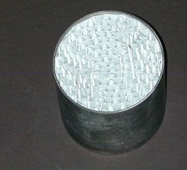
back pressure or flow restriction. The carbon used in the auxiliary chamber of PZEV canisters is
typically extruded into small honeycomb monoliths as shown in Figure 9.
Macropores
Mesopores
Micropores
Figure 8: Pore types and diffusion mechanisms within an activated carbon particle.
15Figure 9: Examples of extruded activated carbon honeycombs like those used in auxiliary
chambers of PZEV canisters.
3.4 Air Intake Systems (AIS)
When the engine is shut off, the concentration of hydrocarbons in the cylinders and
intake manifold is higher than the concentration upstream of the throttle body and air intake. In
the absence of intake airflow, fuel vapors will migrate past the air induction system and into the
atmosphere. These emissions are on the order of 0.1 g per diurnal with some additional losses
during hot-soak cycles. Because of the zero evaporative requirement on PZEV vehicles, these
emissions will be detected in the SHED test and must be controlled. These slow moving bleed
emissions can be captured by incorporating a small hydrocarbon trap into the air induction
system of the vehicle. The earliest designs utilized activated carbon within the air cleaner
element. The size and shape of engine air induction traps can vary from honey combs to carbon
coated paper or thin panels of activated carbon (Figure 10). In some applications, zeolite based
coatings have been applied to metal honeycomb substrates to control air intake evaporative
emissions. This design offers low pressure drop, high HC capture efficiency and clean
desorption. An example of this technology is shown in Figure 11.
Figure 10: Example of carbon shapes used in vehicle air intake systems
16Figure 11: Zeolite based AIS hydrocarbon trap
Because these traps are not intended to capture a large amount of hydrocarbons, their
working capacity is extremely low and they have a very low pressure drop. They are extremely
effective in reducing the HC emissions by 100-200 mg/test which is significant when trying to
meet near zero PZEV limits. Figure 12 compares the AIS emissions from a small four cylinder
as well as a large eight cylinder vehicle both with and without air induction traps. This test
isolated the air induction emissions from the other types of emissions in a SHED test to show
that these traps can be up to 90% efficient in capturing emissions from the air intake system.
Figure 12: Air induction system emissions with and without an AIS carbon trap
3.5 On-Board Refueling Vapor Recovery
On-board refueling vapor recovery (ORVR) systems are designed to capture
hydrocarbons dispersed in the vapor of the fuel tank that are displaced during refueling.
Although the heart of the system is the carbon canister, there are a number of other valves and
seals to prevent escape of vapor through the fuel filler pipe and preventing liquid gasoline from
exiting the fuel tank when tipped beyond horizontal. The displaced vapor is directed into the
carbon EVAP canister and trapped. During engine operation, fresh air is purged through the
canister to regenerate the carbon so that it is ready for subsequent fueling or diurnal events. The
purged vapors are consumed in the combustion process. Today, all new passenger vehicles
manufactured in North America are equipped with ORVR systems.
174.0 On-Board Diagnostic Requirements
Modern EVAP control systems incorporate on-board diagnostic controls that test the fuel
system integrity and insure that they are functioning properly. Fuel tank pressure sensors are
being used to alert the driver when a fuel cap is missing or not sealed properly. This functions
by applying a slight vacuum to the fuel tank and monitors if it is maintained. On OBDII
equipped vehicles, the system will perform an integrity check during normal operation. If the
leak rate exceeds a limit value, the Malfunction Indicator Lamp (MIL) will be illuminated.
During canister purge, the Powertrain Control Module (PCM) monitors the HC air
mixture going into the combustion chamber so that the overall air/fuel ratio does not impact the
vehicle tailpipe emissions. The PCM must control the fuel delivery to each individual cylinder.
The exact control of purge emissions in Flex Fuel Vehicles (FFV) poses challenges as they are
able to use multiple fuels with various vapor pressures.
5.0 Conclusion
• Evaporative emissions from mobile sources have raised health and environmental
concerns, but a number of technologies exist that can greatly reduce VOC emissions
from gasoline-powered vehicles and equipment.
• Regulations are necessary to prevent back-sliding and decontenting of technology
from vehicles and insure that the best available evaporative controls continue to be
installed on vehicles.
• Low permeability rubber and polymers are being deployed in fuel tanks, hoses, seals
and gaskets of modern fuel systems to minimize permeation losses.
• Carbon canisters remain at the heart of vehicle EVAP controls to capture fueling,
diurnal and hot soak emissions of hydrocarbons.
• EVAP controls offer an extremely effective and durable means to control ozone
forming HC emissions over the life of the vehicle.
• PZEV and hybrid vehicles use the most advanced carbon technology as part of the
auxiliary chamber in PZEV canisters and air induction systems to achieve near-zero
evaporative emissions despite low purge volumes.
• The types of technologies deployed on PZEV vehicles can be implemented within the
entire gasoline vehicle fleet and beyond to off-road spark-ignited vehicles and
engines that have yet to benefit from EVAP emission controls.
6.0 References
1) ARB LEV II Staff report: http://www.arb.ca.gov/regact/LEVii/isor.pdf
2) MECA Publication: Emission Control of Small Spark-ignited Off-Road Engines and
Equipment, http://www.meca.org/galleries/default-
file/SORE%20white%20paper%200109%20FINAL.pdf
183) MECA Publication: Emission Control of Two and Three Wheeled Vehicles,
http://www.meca.org/galleries/default-
file/Motorcycle%20whitepaper%20final%20081908.pdf
4) Technologies for Near-Zero-Emission Gasoline-Powered Vehicles, F. Zhao, SAE
International, 2007
5) Impact and control of Canister Bleed Emissions, SAE paper 2001-01-0733
19You can also read