On-Chip Evolution Using a Soft Processor Core Applied to Image Recognition
←
→
Page content transcription
If your browser does not render page correctly, please read the page content below
On-Chip Evolution Using a Soft Processor Core Applied to Image Recognition

            Kyrre Glette and Jim Torresen                        Moritoshi Yasunaga and Yoshiki Yamaguchi
                 University of Oslo                                        University of Tsukuba
             Department of Informatics                                       Graduate School of
     P.O. Box 1080 Blindern, 0316 Oslo, Norway                      Systems and Information Engineering
            {kyrrehg,jimtoer}@ifi.uio.no                          1-1-1 Ten-ou-dai, Tsukuba, Ibaraki, Japan
                                                                    {yasunaga,yoshiki}@cs.tsukuba.ac.jp

                         Abstract                                an approach is the evolution speed but the problem is lack
                                                                 of flexibility. This would be important since there are often
    To increase the flexibility of single-chip evolvable hard-   many degrees of freedom when evolving hardware systems.
ware systems, we explore possibilities of systems with the           Implementing complete evolution in an FPGA has been
evolutionary algorithm implemented in software on an on-         proposed by Tufte and Haddow in [16]. The evolving de-
chip processor. This gives higher flexibility compared to im-    sign is here implemented in the same device as the evo-
plementing an evolutionary algorithm directly in hardware,       lutionary algorithm. A similar approach is proposed by
since the parameters and behaviour of the algorithm can          Perkins et al in [9]. Significant speedup is achieved for non-
easily be changed, and complex operators are more feasible       linear filtering compared to conventional processing. Sev-
to implement. In this paper a Xilinx MicroBlaze soft core        eral custom accelerators in FPGA for solving a protein fold-
processor is used, and the system is implemented in a Xilinx     ing problem have been introduced by Shackleford et al [12].
FPGA. A suitable hardware architecture for image recogni-            On-chip evolution using a prototype of the VLSI (Very
tion has been proposed, and it is applied to a face recogni-     Large-Scale Integration) POEtic chip has also been reported
tion task. Data buses and higher level functions have been       [10]. A robot controller and logic functions were evolved.
utilized in order to reduce the search space for the evolu-      The architecture, specialized for the implementation of bio-
tionary algorithm. Experiments have been performed on            inspired mechanisms, contains an on-chip custom proces-
the physical device, with software running in parallel with      sor, and a bio-inspired array of building blocks.
fitness computation in digital logic. Results show that the          Running complete evolution of image filters within an
MicroBlaze system evolves at half the speed of a Pentium         FGA has been reported by Martinek and Sekanina [7]. In
M system running at 17 times the FPGA clock frequency.           this work the evolution (mutation only) is implemented in
The distinction of a certain face from others is performed       reconfigurable logic. Image filters were evolved in a few
at 94.9% accuracy. In addition, the possibilities for evo-       seconds from corrupted and original pictures. This design
lutionary adaptation over time are explored by introducing       employs data buses, earlier proposed in [11] and [13], and
changes in the training set. The system shows ability to         function-level building blocks, first proposed in [8].
adapt to these changes.                                              The authors have earlier demonstrated System-On-Chip
                                                                 evolution using an embedded hard processor core in an
                                                                 FPGA [1]. This is accomplished by integrating an evolu-
1 Introduction                                                   tionary algorithm running as software on a hard processor
                                                                 IP core with the target EHW implemented in reconfigurable
   Evolvable hardware (EHW) seems useful for systems             logic. In this paper an alternative approach is explored by
submitted to unpredictable, time-varying environments [20,       using a soft processor core. This allows for portability to a
14]. Such systems will also often be part of embedded ap-        greater range of FPGAs, including cheaper devices.
plications, and therefore compact, on-chip solutions will be         In our system, all parts of the evolution (except the eval-
preferred.                                                       uation of individuals which is implemented in digital logic)
   There have been undertaken some implementations of            are undertaken in software, providing a flexible system for
single-chip evolution earlier. Kajitani et al have introduced    later modifications. This is slower than implementing the
several LSI (Large-Scale Integrated Circuits) devices with       evolution in dedicated hardware, but it is expected that the
evolution performed in hardware [5, 6]. The benefit of such      fitness evaluation time will still be the most time consum-
ing part. This balanced software-hardware approach will al- FPGA
BRAM
low for a low implementation effort while still being able to 64KB
have a single-chip design, suitable for embedded real-world LMB
applications.
The EHW system is applied to a face image recognition TARGET MicroBlaze
EHW processor PERIPHERAL
task. Experiments on image recognition by EHW were first
reported by Iwata et al in [4]. An FPLA device was utlized
OPB
for recognition of black and white images. An EHW face
image classifier system has been developed by Yasunaga et
UART PERIPHERAL SDRAM
al in [21], in which the classifier function is directly coded CONTROLLER
in large AND gates. Evolution is performed offline and the
final system is synthesized. This approach gives rapid clas-
sification in a compact circuit, but lacks the run-time recon-
figurability. Another classifying system has been proposed
in [15], also employing AND gates, in combination with Figure 1. Example hardware architecture in-
OR gates. These systems have in common the selection of cluding our target EHW.
one category from a set of candidate categories.
The image recognition task proposed in this paper will
be restricted to recognizing one face out of a set of candi-
dates. That is, the system reports an input as either a posi- The bus system is a part of IBM’s CoreConnect archi-
tive match to the trained face category, or a negative match. tecture [19]. The On-chip Peripheral Bus (OPB), with a
Such an application could be imagined for an image-based data width of 32 bits, is used to connect the processor and
lock for mobile devices, or cameras trained to recognize one the peripherals. The Processor is connected to dual-port
particular person. SRAM, called Block RAM (BRAM), using a dedicated Lo-
The next section introduces the architecture and the im- cal Memory Bus (LMB). This bus features separate 32-bit
plementation of the on-chip EHW system, including both wide channels for program instructions and program data,
hardware and software aspects. Results from the imple- using the dual-port feature of the BRAM. The LMB makes
mentation are given and discussed in Section 3. Finally, single-cycle access of BRAM possible.
Section 4 concludes the paper. The target evolvable hardware is at the moment con-
nected to the OPB. This will be detailed in section 2.2. Var-
2 The On-Chip Evolution System ious on-chip peripherals are also connected to the OPB, in-
cluding a UART for RS-232 serial communications. An
This section details the hardware and software architec- SDRAM controller can also be connected to the OPB
ture of the evolvable hardware system. The evolvable hard- should more memory be needed.
ware system is entirely implemented on one FPGA chip. The on-chip system is built using the Xilinx Embedded
The core modules are the processor, the RAM and the target Development Kit (EDK) [17]. EDK is a collection of Intel-
EHW module. The evolutionary algorithm, stored in RAM, lectual Property (IP) cores and tools for building embedded
runs on the embedded processor, and the target EHW mod- systems on FPGAs. The hardware and software parts of the
ule is used for fitness evaluation. This module is built as a system can be specified parametrically through various con-
reconfigurable hardware module which accepts a bit string figuration files, and net lists and libraries are automatically
as configuration. generated.
2.1 System Overview 2.2 Target Evolvable Hardware
The architecture consists of a set of modules intercon- The target EHW is implemented as an OPB slave pe-
nected with buses, as seen in Fig. 1. The MicroBlaze soft ripheral module – see Fig. 2. Interfacing with the OPB bus
processor core provided by Xilinx is central in the system. has been simplified by the use of a Xilinx IP Interface core
It employs a 32-bit, 3-pipeline stage RISC architecture and (IPIF). This provides a simpler interface standard, the Xil-
is optimized for implementation in the Xilinx FPGAs. It inx IPIC, for the user module.
is user configurable, allowing for use of various interfaces Control and configuration of this module are undertaken
and functionality according to system needs and constraints. through register write operations. Genome values are writ-
Amongst others, hardware division and multiplication, and ten to registers which are again connected to the configura-
a floating point unit (FPU), are supported [18]. tion inputs of the functional unit array. Registers are alsoOPB TARGET EHW MODULE FUNCTIONAL UNIT ARRAY
OPB fij fij fij
IPIF
FUNCTIONAL
UNIT ARRAY
fij fij fij
. . .
. . ... .
. . .
IPIC Input Config Output
interface ffijij ffijij ffijij
Input Output
CONTROL LOGIC
Config
Figure 2. The architecture of the target EHW Figure 3. The architecture of the functional
system. unit array subsystem.
# Description Function
provided for feeding the EHW with inputs and for storing 0 Saturated Add O = A + B, F F if (A + B) > F F
the outputs. 1 High Threshold O = F F if A > C2 , else 0
2 Range O = F F if C1 < A < C2 , else 0
3 Greater O = F F if A > B, else 0
2.2.1 Functional unit array 4 Bitwise AND O = A AND B
5 Bitwise OR O = A OR B
The functional unit array (FUA), see Fig. 3, is a general
6 Average O = (A + B) >> 1
structure used for EHW. It is based on the principle that the
7 Half O = A >> 1
configuration of the FPGA itself is not changed, but a virtual
circuit which is implemented on top of it can be reconfig-
ured. Hence the names ”Virtual FPGA” [3] or ”Virtual Re- Table 1. Functions used by units in the image
configurable Circuit” [11] have been proposed for circuits recognition task. Inputs are A and B, ouput is
building on the same principles. The behavior of the FUA O. C1 and C2 are constants available to each
is achieved by writing configuration data to registers which unit.
in turn control the functionality of each unit, fi,j in the ar-
ray. A fixed set of functions and connections to other units’
outputs are available in each functional unit. The configu-
2.2.2 Image recognition application
ration lines control multiplexers which select which inputs
and functions to use. The system bears resemblance to the The FUA has been applied to an image recognition applica-
VRC in [11]. tion. For this, 8-bit wide databuses are used as inputs and
Our FUA consists of a fixed-size array of functional outputs of the units, which is also the data width of one pixel
units. The array consists of C columns of R units from from the input image. The array has R = 8 rows and C = 5
input to output. Each unit has I inputs, each of which can columns. There are I = 2 inputs and there are F = 8 func-
be connected to any output in the previous column. The tions available for each unit. The functions are summarized
unit’s output is a result of any of F functions. The function in table 1. The specific functions are chosen because they
of each unit and its inputs are configurable. They are deter- are believed to be useful for an image recognition task. The
mined by evolution, in the way that each individual’s binary threshold and range functions give a possibility to discrim-
genome is sent to the FUA and mapped to the configuration inate pixels based on their intensity value. Combined with
lines. Fitness is then calculated by feeding a number of in- the saturated adder, threshold element-like functionality, as
put vectors on the inputs of the first column, and reading seen in artificial neural networks, can be achieved. In addi-
the results from the outputs of the last column. The array tion, two global constants, C1 and C2 , are available to each
is constructed in a pipelined fashion, that is, registers are unit. These are coded in the genome for each individual as
connected to the outputs of each layer. Currently, this is not 8-bit values.
exploited for fitness evaluation. Only one input vector is The input images have a resolution of 8x8 pixels, 64 in
evaluated at a time. total, while each column in the FUA consists of 8 units,0 1 2 3 4 5 6 7
inputs of FUA
input image selector
column
Figure 4. The genome selects one pixel from
each row of the 64-pixel picture, giving 8 pix-
els for the first column of the FUA.
capable of selecting from 8 inputs. To save genome size and
circuit space, as well as simplifying the design, a ”selector
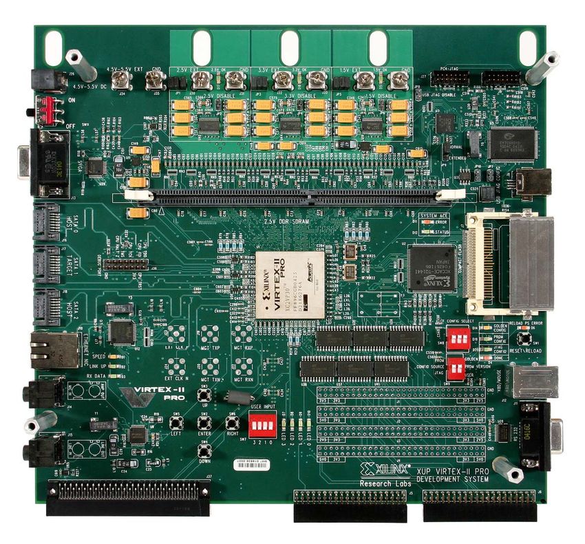
Figure 5. The prototype board with the Virtex-
column” is introduced. Basically this imposes a restriction
II Pro FPGA. Source: Xilinx
of only letting the unit in one row select a pixel input from
the corresponding row of 8 pixels in the image. Thus, only
3 bits are needed code for a pixel from each row, which
gives a total of 24 bits of the genome for the entire selector
column. The selected pixels are then passed on to the inputs 2.3 The Hardware Platform
of the regular FUA. See Fig. 4.
The design is synthesized for a Xilinx Virtex-II Pro
This functionality could have been implemented in hard-
(XC2VP30) – see Fig. 5. This device contains 30,816 logic
ware by having the first column of the FUA be populated
cells, 2,448 Kbit BRAM, and two PowerPC 405 (PPC) em-
with special selector units, or hard-coded ”Add A, 0” units
bedded processors. The FPGA is situated on a Xilinx XUP
(using already defined functionality in the standard units),
Virtex-II Pro development board, which also contains a con-
each of them connected to a corresponding row of image
figuration PROM and various useful interfaces.
pixels. However, in the current implementation, this selec-
tion is done in software on the MicroBlaze, as this lets us
transfer only 8 instead of 64 pixels over the data bus for
2.4 The Genetic Algorithm Implementation on
each vector. Depending on the source of the data vectors
the MicroBlaze
this can be moved to hardware in future versions.
A Genetic Algorithm (GA) was implemented to run on
The last column of the array gives 8 8-bit outputs. How-
the MicroBlaze processor. 64KB of BRAM was used as a
ever, only the 8-bit output of the topmost functional unit is
combined instruction and data memory. The program was
used for the classification of the image.
written in C and compiled and linked using the MicroB-
The encoding of each functional unit in the genome laze version of the GNU GCC compiler tools. However, the
string is as follows: limited amount of RAM makes it necessary to omit the use
of most standard C library functions. The code was devel-
Function (3 bit) Input 1 (3 bit) Input 2 (3 bit) oped with verification and simulation on a PC workstation
in mind. It is therefore possible to compile the program
This gives a total of U = log2 F + I × log2 R = 9 bits for both for the MicroBlaze using GCC and for a PC worksta-
each unit. The entire genome is encoded as follows: tion using Microsoft Visual C, with code differences only
for low-level functionality.
C1 ,C2 (16b) Sel. col.(24b) f0,0 (9b) ... f4,7 (9b) As the MicroBlaze can be configured with a FPU, some
of the code uses floating point. However, if FPGA resource
The total amount of bits in the genome is then 2 × 8 + usage is critical, the FPU should be removed. This im-
R × log2 R + C × R × U = 400. plies software emulation of floating point, which should beavoided in order to reduce code size and execution speed. Resource Used Available Percent
Conversion to fixed point arithmetic could then be consid- Slices 2990 13696 21
ered. Dynamic memory management is not supported for Slice Flip Flops 1037 27392 3
the MicroBlaze. Allocation of memory for data structures 4 input LUTs 5488 27392 20
such as population and individuals is handled manually.
The GA implemented for this experiment follows the
Simple GA style, given by Goldberg [2]. Fitness scaling Table 2. Post-synthesis device utilization
for the EHW module implemented on the
has been implemented, including linear scaling. A fitness-
proportionate selection scheme is implemented through the XC2VP30.
use of a roulette wheel mechanism. The individuals are
sorted with the qsort algorithm. For mutation, instead of
having one probability of mutation for every bit in the negative (0) then 1 is added to the fitness function. On the
genome, a quicker solution has been adopted. The num- other hand, if they equal and the value is equal to one, 4
ber of mutations, n, for the whole genome is calculated by is added. In this way, an emphasize is given to the outputs
a random lookup in a 10-position array. Then, n random being positive. This has shown to be important for getting
places are mutated (bit-flipped) in the genome. This is more faster evolution of well performing circuits. The function
efficient than performing a check for every bit if a mutation sums these values for the training image vectors (vec).
should occur or not. For the evolution, a population size of 30 is used. Elitism
is used, thus, the best individuals from each generation
2.5 Fitness Function and GA Parameters are carried over to the next generation. The (single point)
crossover rate is 0.9, thus the cloning rate is 0.1. A roulette
wheel selection scheme is applied, and linear scaling is
The fitness of the face recognition system is based on the
used. The mutation rate is expressed as a probability for
system’s ability to recognize one face from a range of differ-
a certain number, n, of mutations on each genome. The
ent faces. The images are taken from the ”Olivetti Research
probabilities are as follows:
Laboratory Database of Faces”1 . The original resolutions
of the images were 92x112 and there were 400 faces di- n 0 1 2 3
7 2 1
vided over 40 people, giving 10 face images per person. In p(n) 0 10 10 10
our experiment the images were downsampled to 8x8 pixels
and 10 categories were used, giving a total of 100 64-pixel 3 Results
vectors. These are stored in BRAM.
90 of the vectors were used for training of the system, This section presents and discusses the results of our im-
while the remaining 10 were used for verification after the plementation and experiments.
evolution run. Each configuration of the hardware is fed
with the 90 training vectors (vec), and fitness is based on 3.1 Device utilization and clock speed
the system’s ability to give a positive output for the 9 image
vectors belonging to the right person, and a negative output The total resource usage for the system, including the
for the rest. Output values from the system are compared target EHW, the MicroBlaze, bus structure and peripherals,
to target values d, which are positive (d = 1) for vectors is 5113 slices, equalling 38% of the XC2VP30. The sys-
belonging to the right person, and negative for all other vec- tem was implemented to run at 100MHz. It is possible that
tors (d = 0). An output value of F F (hexadecimal) from higher frequencies are attainable, up to a limit of around
the topmost functional unit in the last column is considered 150MHz. The MicroBlaze has a maximum frequency of
a positive output (o = 1), while anything else is considered 150MHz on the Virtex-II Pro, and the target EHW has
a negative output (o = 0). a post-synthesis maximum estimate of 148MHz. Table 2
The fitness function can be expressed in the following shows the amount of logic used for the target EHW mod-
way: ule. A maximum of 21% of the FPGA’s total resources are
used by this module. The post-synthesis resource usage of
0 if o = d the MicroBlaze processor is 1731 slices, of which 33% is
F = x where x = 1 if o = d = 0 (1)
used for the FPU.
vec 4 if o = d = 1
For each input image vector the computed output o is com- 3.2 Evolution speed
pared to the target value d. If these equal and the value is
The speed of an evolution run of 1000 generations was
1 http://www.cl.cam.ac.uk/Research/DTG/attarchive/facedatabase.html measured for the on-chip EHW system and a Pentium M PCEHW PC PC fitness determination of each individual. This is because
EHW
Clock speed(MHz) 100 1700 17 pixel selection and transfer over the system bus, as well as
Evolution speed(ms) 10914 4993 0.46 the readback of the FUA output and comparison with the
target value, is done for each training vector. Thus, the low
program execution speed and bus transfer rate contribute to
Table 3. Evolution speeds on the on-chip making the fitness overhead much slower than the hardware
EHW and PC systems. The last column indi- fitness evaluation.
cates the ratio between the first and second
columns. 3.3 Image Recognition Performance
Individuals with maximal fitness values were evolved af-
12000
Fitness calculation
ter an average of 1133 generations over 20 evolution runs.
10000 Individual evaluation
A solution with maximal fitness value was found in every
GA w/o fitness run. The average evolution time is then 12.4 seconds. For
8000 verification, the last vector in each category was used. This
means that there were 10 vectors to test the accuracy, where
Time(ms)
6000
the evolved system would need to produce a ’1’ for one of
4000
these, and ’0’ for the others. Due to the lack of more verifi-
cation vectors, the position of the vector within the category
2000 was changed, and the remaining vectors were used for train-
ing vectors for a new evolution run. This was repeated 10
0
Pentium M 1.7GHz MicroBlaze EHW 100MHz
times, until all of the vectors in a category had served as a
verification vector. The accuracy over all the outputs from
all the evolution runs is 94.9% correct outputs. Also, 7 of
Figure 6. Evolution speeds. these 10 evolution runs produced individuals which gave
correct outputs for all vectors.
for speed comparison. As can be seen in Table 3, the evo- 3.4 Real-time adaptation
lution runs faster on the PC. However, although the evolu-
tion runs 2.2 times faster, the processor runs at 17 times the To explore possibilities for using the system with appli-
clock frequency of the MicroBlaze system. This is mainly cations where the environment is changing over time, an
due to the fact that the evaluation of individuals is carried adaptation experiment was carried out. In a real-world ap-
out in hardware on the on-chip EHW system whereas it is plication one would imagine the training set changes, by
simulated in the PC system. In order to better analyze the introducing new face images of either the target face cate-
speed of different parts of the evolution process, three dif- gory or the other category. It could also be imagined that
ferent measures were made. The first measure indicates the some training vectors would have to be removed, based on
time used by the GA without any form of fitness evalua- timestamps for example.
tion, ie. all the fitness values were set directly to 0 in the We simulated such a change in the training set by re-
program. The second measure indicates the time spent on moving one vector and adding another vector from the tar-
evaluation of the individuals. That is, the time used for cal- get face category every 500 generations. However, as there
culating outputs from inputs to the FUA. The third measure were only 9 images available for training in each category,
is the time used for fitness calculation. This consists of the 8 images were used for the training set and 1 image cycled
calculation of a fitness value based on the training vectors as the not used image. To introduce some more change, all
and outputs of the FUA, as well as pixel selection and trans- the pixels in the added vector were multiplied by four.
fer to the FUA. The results are summarized in Fig. 6. It is The experiment was run for 5000 generations. The re-
clear that the sum of the operations related to fitness are the sults can be seen in Fig. 7. By observing the fitness value
most time-consuming parts for both of the systems. The of the best individual of each population, one can get an
bottleneck in the PC program is clearly the evaluation of impression of the system’s adaptability. Some of the train-
individuals, which is simulated in software. The execution ing set changes are clearly observable by a drop in fitness,
time for this part is greatly reduced in the on-chip system. If while other changes do not affect the fitness value. The re-
the target EHW module increases in size or complexity, this cover time from the fitness value drops seems to vary from
difference will become even more significant. The hard- around 50 to 500 generations, which is equivalent to 0.5 to
ware system’s bottleneck is the overhead associated to the 5.5 seconds of run time on the MicroBlaze system.105
100
95
90
85
Best fitness
Avg. fitness
80
0 500 1000 1500 2000 2500 3000 3500 4000
Figure 7. Population fitness over generations, showing the fitness of the best indiviudal and the
population average fitness. Temporary drops in fitness can be observed when the training set is
modified. Notice that the y-axis only shows fitness values from 80 to 105. 104 is the maximum
possible fitness value.
3.5 Discussion evolution would tend towards the execution time used by
only the GA. In such a case the on-chip system could per-
The FPGA resource usage of the system is not a prob- form at twice the speed, or better, than the PC system. How-
lem with the FPGA used in our experiments. But for low- ever, an increased degree of hardware specialization comes
cost applications, it would be desirable to use a smaller, less at the prize of a higher implementation effort and increased
expensive FPGA device. As [11] points out, the disadvan- resource usage. In general, performance needs for the ap-
tage of a virtual circuit approach is the high implementation plication should be considered up against implementation
cost. Much of this cost comes from interconnect between costs. A speed performance comparison with the system
the units and multiplexers for selecting the inputs to each described in [1] should be the subject of future work.
unit. Other connection schemes should be explored. At the
A face recognition performance of 94.9% is acceptable,
expense of a slight speed loss, a possibility could be to use
but the accuracy measure might not reflect real-world per-
a kind of addressing or broadcasting scheme for sending
formance. Since only one category of faces is to be recog-
the data to the next layer of units. The MicroBlaze proces-
nized, more verification vectors for this category are desir-
sor can be configured to take up less resources by remov-
able. This would give a clearer picture of the accuracy of the
ing some functionality. A removal of the FPU would give
system. In future work, it could also be explored how this
the most significant decrease in resource usage. This does
system would perform when expanded to a multi-category
not necessarily have to imply a performance penalty if the
classification system, like the ones seen in [21] and [15].
program code is written to avoid the use of floating point
In that case, the current FUA would be duplicated to the
instructions.
amount of categories desired, and the amount of high out-
Using 12.4 seconds on average to evolve a system with
put values from the last column in each FUA could be used
maximum fitness, the speed of the on-chip system is cur-
as input to a max detector for determination of a category.
rently acceptable. It should also be noted that systems with
relatively high fitness values are available earlier in the evo- Real-time adaptation to a changing environment is a
lution runs, which are usable until a better solution has been goal for our on-chip evolutionary systems. The initial ex-
found. However, as future tasks may be more complex to periments of introducing changes to the training set seem
evolve, a speed increase would be desirable. As pointed promising, as the system seems to regain a high fitness in
out in section 3.2, there is a large overhead associated with short time. But in order to explore adaptation further, a
fitness calculation in software. If feeding of the training larger training set is desirable for the face recognition appli-
vectors to the FUA and fitness value calculation would be cation. In a real-world application, one target EHW module
moved to hardware, a significant speed increase would be configured with the best individual could be used as an op-
possible. The FUA would achieve a much higher through- erational circuit, while a second target EHW module is used
put, and the pipelined nature of the design could be ex- for fitness evaluation for the evolving population. One ex-
ploited. In this case the total execution time for the on-chip ample of an adapting application could be a camera with anintegrated chip, assigned to detect a certain person. Over [7] T. Martinek and L. Sekanina. An evolvable image fil-
time the system could receive new images of the person, or ter: Experimental evaluation of a complete hardware im-
images of other persons which should not be detected, to be plementation in fpga. Lecture Notes in Computer Science,
added to the training set. 2005(3637):76–85, 2005.
[8] M. Murakawa, S. Yoshizawa, I. Kajitani, T. Furuya,
M. Iwata, and T. Higuchi. Hardware evolution at function
4 Conclusions level. In Proc. of Parallel Problem Solving from Nature IV
(PPSN IV), volume 1141 of Lecture Notes in Computer Sci-
We have presented a system-on-chip EHW system using ence, pages 62–71. Springer-Verlag, September 1996.
a soft IP core processor for running the evolutionary algo- [9] S. Perkins, P. Porter, and N. Harvey. Self-contained
spatially-structured genetic algorithm for signal processing.
rithm. This has shown reasonable performance combined
In J. Miller et al., editors, Evolvable Systems: From Biology
with flexibility for experimentation. The configurability of
to Hardware. Third International Conference, ICES 2000,
the MicroBlaze core makes such a combination interesting volume 1801 of Lecture Notes in Computer Science, pages
for applications in low-cost systems. The EHW architec- 165–174. Springer-Verlag, 2000.
ture proposed utilizes data buses and higher level functions [10] D. Roggen, Y. Thoma, and E. Sanchez. An evolving and de-
in order to reduce the search space. The inputs of the FUA veloping cellular electronic circuit. In J. Pollack, M. Bedau,
and the functions available to the units are adapted to the P. Husbands, T. Ikegami, and R. A. Watson, editors, ALife9:
image recognition task. These measures make it possible Proceedings of the Ninth International Conference on Arti-
to use evolution for a relatively complex task. The experi- ficial Life, pages 33–38, Boston, MA, 2004. MIT Press.
[11] L. Sekanina. Virtual reconfigurable circuits for real-world
mental results indicate that the system is suitable for further
applications of evolvable hardware. Lecture Notes in Com-
experiments and development of real-time on-chip adapta- puter Science, 2003(2606):186–197, 2003.
tion. [12] B. Shackleford et al. A high-performance, pipelined, FPGA-
based genetic algorithm machine. Journal of Genetic Pro-
Acknowledgments gramming and Evolvable Machines, 2(1):33–60, 2001.
[13] J. Torresen. Exploring knowledge schemes for efficient evo-
lution of hardware. In Proc. of the 2004 NASA/DoD Confer-
The research is funded by the Research Council of ence on Evolvable Hardware.
Norway through the project Biological-Inspired Design of [14] J. Torresen. Possibilities and limitations of applying evolv-
Systems for Complex Real-World Applications (project no able hardware to real-world application. In R. Harten-
160308/V30). stein et al., editors, Field-Programmable Logic and Appli-
cations: 10th International Conference on Field Program-
mable Logic and Applications (FPL-2000), volume 1896
References
of Lecture Notes in Computer Science, pages 230–239.
Springer-Verlag, 2000.
[1] K. Glette and J. Torresen. A flexible on-chip evolution [15] J. Torresen. Two-step incremental evolution of a digital logic
system implemented on a Xilinx Virtex-II Pro device. In gate based prosthetic hand controller. In Evolvable Systems:
Evolvable Systems: From Biology to Hardware. Sixth Inter- From Biology to Hardware. Fourth International Confer-
national Conference, ICES 2005, volume 3637 of Lecture ence, (ICES’01), volume 2210 of Lecture Notes in Computer
Notes in Computer Science, pages 66–75. Springer-Verlag, Science, pages 1–13. Springer-Verlag, 2001.
2005. [16] G. Tufte and P. C. Haddow. Prototyping a ga pipeline for
[2] D. Goldberg. Genetic Algorithms in search, optimization, complete hardware evolution. In 1st NASA / DoD Workshop
and machine learning. Addison–Wesley, 1989. on Evolvable Hardware (EH ’99), pages 18–25, 1999.
[3] P. Haddow and G. Tufte. Bridging the genotype-phenotype [17] Xilinx Inc. Embedded System Tools Reference Manual, Feb-
mapping for digital fpga. In Proc. of the Second NASA/DoD ruary 2005.
Workshop on Evolvable Hardware, 2001. [18] Xilinx Inc. MicroBlaze Processor Reference Guide, May
[4] M. Iwata, I. Kajitani, H. Yamada, H. Iba, and T. Higuchi. 2005.
A pattern recognition system using evolvable hardware. In [19] Xilinx Inc. Processor IP Reference Guide, February 2005.
Proc. of Parallel Problem Solving from Nature IV (PPSN [20] X. Yao and T. Higuchi. Promises and challenges of evolv-
IV), volume 1141 of Lecture Notes in Computer Science, able hardware. In T. Higuchi et al., editors, Evolvable Sys-
pages 761–770. Springer-Verlag, September 1996. tems: From Biology to Hardware. First International Con-
[5] I. Kajitani et al. A myoelectric controlled prosthetic hand ference, ICES 96, volume 1259 of Lecture Notes in Com-
with an evolvable hardware lsi chip. Technology and Dis- puter Science, pages 55–78. Springer-Verlag, 1997.
ability, 15(2):129–143, 2003. [21] M. Yasunaga, T. Nakamura, I. Yoshihara, and J. Kim.
[6] I. Kajitani, T. Hoshino, N. Kajihara, M. Iwata, and Genetic algorithm-based design methodology for pattern
T. Higuchi. An evolvable hardware chip and its application recognition hardware. In J. Miller et al., editors, Evolvable
as a multi-function prosthetic hand controller. In Proc. of Systems: From Biology to Hardware. Third International
16th National Conference on Artificial Intelligence (AAAI- Conference, ICES 2000, volume 1801 of Lecture Notes in
99), pages 182–187, 1999. Computer Science, pages 264–273. Springer-Verlag, 2000.You can also read