Queensland Plumbing and Wastewater Code - Version 1: 2019
←
→
Page content transcription
If your browser does not render page correctly, please read the page content below
0
    Queensland Plumbing and Wastewater
    Code
    Version 1: 2019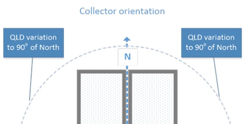
Queensland Plumbing and Wastewater Code

Table of Contents
Introduction and general provisions ............................................................................................ 4
    Commencement                                                                                                                    4
    Introduction                                                                                                                    4
    Purpose of the Queensland Plumbing and Wastewater Code                                                                          4
    Relationship with the Plumbing Code of Australia                                                                                4
    Part A1 Application                                                                                                             4
    A1.0 Compliance with the Queensland Plumbing and Wastewater Code                                                                4
    A1.1 Meeting the performance requirements                                                                                       4
    Part A2 Interpretation                                                                                                          5
    A2.0 Definitions                                                                                                                5
    A2.1 Referenced standards                                                                                                       9
    A2.2 Compliance with all performance requirements                                                                               9
    Part A3 Documents Adopted by Reference                                                                                          9
    A3.0 Schedule of referenced documents                                                                                           9
    A3.1 Restrictions and exclusions                                                                                                9

Section B – Water Services ........................................................................................................ 10
    Part B1 Cold Water Services                                                                                                   10
    B1.0 Scope                                                                                                                    10
    B1.1 Building supply pipes to water main standard                                                                             10
    B1.2 Water meters for new premises                                                                                            11
    B1.3 Water conservation for class 1 and class 2 buildings                                                                     11
    B1.4 Water storage tanks                                                                                                      12
    B1.5 Integrated basins and Water Closet cistern                                                                               12
    Part B2 Heated Water Services                                                                                                 13
    B2.0 Scope                                                                                                                    13
    B2.1 Installation of solar heated water systems                                                                               13
    Part B3 Non Drinking Water Services                                                                                           14
    Refer to Part B3 of the Plumbing Code of Australia.                                                                           14
    Part B4 Fire-Fighting Water Services                                                                                          14
    Refer to Part B4 of the Plumbing Code of Australia and the Building Act 1975.                                                 14
    Part B5 Cross-Connection Control                                                                                              14
    Refer to Part B5 of the Plumbing Code of Australia.                                                                           14
    Part B6 Rainwater Harvesting and Use                                                                                          14
    Refer to Part B6 of the Plumbing Code of Australia.                                                                           14

Section C – Sanitary Plumbing and Drainage Systems ............................................................ 15
    Part C1 Sanitary Plumbing Systems                                                                                             15
    C1.0 Scope                                                                                                                    15
Version 1: 2019
                                                                                                                                 Page 2 of 25
Queensland Plumbing and Wastewater Code

     Part C2 Sanitary Drainage Systems                                                                                                        15
     C2.0 Scope                                                                                                                               15
     C2.1 Building sanitary drain to sewerage system standard                                                                                 16
     C2.2 Connection of appliances and fixtures to grease arrestors                                                                           16
     C2.3 Requirements for grease arrestors                                                                                                   16
     C2.4 Vent pipes to be covered                                                                                                            17

Section D – Excessive Noise ...................................................................................................... 17
     Refer to Section D of the Plumbing Code of Australia.                                                                                    17

Section E – Facilities ................................................................................................................... 17
     Refer to Section E of the Plumbing Code of Australia.                                                                                    17

Section F1 – On-site Wastewater Management Systems ......................................................... 18
     Part F1 On-site Wastewater Management Systems                                                                                            18
     F1.0 Scope                                                                                                                               18
     F1.1 On-site Wastewater Management Systems                                                                                               18
     F1.2 Greywater Use Facility                                                                                                              19
     F1.3 Land application area                                                                                                               20
     F1.4 Composting, chemical and incinerating toilets                                                                                       21

Appendix ...................................................................................................................................... 24
     Part 1 – Closed loop greywater treatment systems                                                                                         24
     Part 2 – Setback Distances                                                                                                               24

Version 1: 2019
                                                                                                                                             Page 3 of 25
Queensland Plumbing and Wastewater Code
Introduction and general provisions
Commencement
Queensland Plumbing and Wastewater Code Version 1: 2019 commences on 1 July 2019.
Introduction
Purpose of the Queensland Plumbing and Wastewater Code
The Queensland Plumbing and Wastewater Code (QPW code) sets out Queensland specific plumbing
and drainage standards.
The QPW code:
(a) adopts standards in relation to matters not covered by the Plumbing Code of Australia (PCA) (National
Construction Code, Volume 3) or
(b) imposes higher standards over and above the requirements of the PCA or
(c) replaces requirements of the PCA.
Relationship with the Plumbing Code of Australia
The PCA provides a nationally uniform set of technical plumbing and drainage standards. Where there is
any inconsistency between the PCA and the QPW code, or the QPW code has additional requirements,
the QPW code prevails.
Part A1 Application
A1.0 Compliance with the Queensland Plumbing and Wastewater Code
The QPW code has been designed to provide performance solutions to meet the statutory requirements of
the Plumbing and Drainage Act 2018 (the Act).
Objectives and functional statements are informative only and are included to provide an aid to interpreting
the performance requirements. Objectives are the community expectations and functional statements
describe how to meet those community expectations.
Compliance with the QPW code is achieved by satisfying the performance requirements.
A1.1 Meeting the performance requirements
Performance requirements have been developed to meet the objectives and functional statements. The
deemed-to-satisfy solutions provide a simple and direct manner of meeting the performance requirements.
Where legislation requires compliance with the QPW code, compliance with the performance
requirements is mandatory.
The performance requirements can only be satisfied by a:
(a) deemed-to-satisfy solution; or
(b) performance solution; or
(c) combination of the solutions of (a) and (b).
Version 1: 2019
Page 4 of 25Queensland Plumbing and Wastewater Code
Part A2 Interpretation
A2.0 Definitions
Unless noted otherwise, all terms have the same meaning as defined in the Act, Plumbing and Drainage
Regulation 2019 (the Regulation), PCA or a relevant Australian/New Zealand Standard.
If a provision (including a definition) in the QPW Code is inconsistent with a provision in the PCA or in a part
of the Queensland Development Code (QDC) prescribed by regulation, the QPW Code provision prevails
to the extent of the inconsistency.
If a provision (including a definition) in the PCA is inconsistent with a provision in a part of the QDC
prescribed by regulation, the provision in the QDC prevails to the extent of the inconsistency.
Note: Italicised words within the body of the text, other than legislation titles, are defined below.
amenity means an attribute which contributes to the health, physical independence, comfort and
wellbeing of people.
automatic switching device means a device that controls the water supply to plumbing outlets by
automatically switching from rainwater tank water to the service provider’s water supply when the water
level in the rainwater tank is insufficient to meet the premises demand.
class 1, 2, 3, 4, 5, 6, 7, 8, 9 and 10, in relation to a building, mean the definitions as specified in the PCA.
closed loop greywater treatment system means a system incorporating:
(a) a source water tank containing greywater from appliance/s;
(b) a greywater treatment plant;
(c) provisions for make-up water;
(d) provisions for bleed water to be disposed of to the sewer or approved discharge point; and
(e) a treated water storage tank used to supply the treated water to appliance/s for re-use.
cold water service means supply pipes that supply cold water.
common property has the meaning provided in section 10 of the Body Corporate and Community
Management Act 1997.
community titles scheme see section 10 of the Body Corporate and Community Management Act 1997.
complying valve means a device incorporated as part of the water meter which a water service provider
can use to securely restrict the flow of water, either partially or fully, to the meterable premises, installed
upstream of a water meter.
deemed-to-satisfy solution means a method of satisfying the performance requirements.
design life means the period during which the item is designed to meet the performance criteria. It is to
be a minimum of 15 years.
drinking water means water intended primarily for human consumption but which has other domestic
uses.
dry-vault toilet means a system for disposing human waste incorporating a chamber that:
(a) receives and treats the waste; and
(b) uses a biological degradation or dehydration process to treat the waste; and
(c) does not use water other than water for cleaning or to help the biological degradation process.
efficient irrigation system means a fixed outdoor irrigation system consisting of a network of permanent
piping connected to emitters which has been designed and installed to water a specific landscape area
and will reduce the maximum output capacity.
Version 1: 2019
Page 5 of 25Queensland Plumbing and Wastewater Code
emitter means a device of any kind fitted on a pipe which is operated under pressure to discharge water
in a spray, mist or drip form. Common types of emitters include drippers, micro-sprayers, pop-up and
gear-drive sprays, and fixed sprinkler heads.
greasy waste means liquid waste containing grease or oils, that is generated by a commercial business
generally from food preparation activities that is discharged into sanitary drainage.
greywater means wastewater from a bath, basin, kitchen, laundry or shower, whether or not the
wastewater is contaminated with human waste.
greywater diversion device means a device that:
(a) diverts greywater to sanitary drainage or a land application area; and
(b) if the device forms part of a greywater use facility:
(i) automatically diverts greywater from the facility to sanitary drainage if the facility does not work
properly or at all; and
(ii) allows greywater from the facility to be manually diverted from the facility to sanitary drainage.
greywater treatment plant means a plant installed on premises for treating, on the premises, greywater
produced on the premises.
greywater use facility means a facility consisting of:
(a) a greywater diversion device and a land application area; or
(b) greywater treatment plant, with or without a land application area.
heated water has the meaning given by the Plumbing Code of Australia.
land application area means an area where greywater, or effluent from an on-site sewage treatment
plant is disposed of by subsurface or surface irrigation.
loss means either: physical damage, financial loss or loss of amenity.
meterable premises means:
(a) all class 1 buildings;
(b) each lot within a community title scheme, including the common property, in a water service provider’s
area;
(c) the sole-occupancy unit of a class 2, 4, 5, 6, 7 or 8 building in a water service provider’s area;
(d) each storey of a class 5 building in a water service provider’s area where the building consists of more
than one storey and sole-occupancy units are not identified at the time of the building’s plumbing
compliance assessment.
on-site sewage facility means:
(a) a facility, other than an environmentally relevant on-site sewage facility, installed on premises, that
includes:
(i) an on-site sewage treatment plant on the premises for treating sewage produced on the
premises; and
(ii) either
a. a land application area on the premises for disposal of the effluent produced by the on-site
sewage treatment plant; or
b. a tank for storing on the premises the effluent produced by the on-site sewage treatment
plant for later disposal off the premises by collection from the tank; or
(b) a facility, other than an environmentally relevant on-site sewage facility, installed on premises, that:
(i) includes an on-site sewage treatment plant on the premises for treating sewage produced on
the premises; and
Version 1: 2019
Page 6 of 25Queensland Plumbing and Wastewater Code
(ii) disposes of the effluent produced by the on-site sewage treatment plant off the premises -
a. if the facility is installed only for testing purposes – into a sewage system; or
b. by common effluent drainage; or
c. in another way, stated in the permit issued for the installation of the facility; or
(c) a dry-vault toilet or a chemical, composting or incinerating toilet.
on-site sewage treatment plant means a sewage treatment plant that is, or is designed to be part of an
on-site sewage facility installed on premises.
on-site wastewater management system means a system installed on premises that receives and treats
wastewater generated on the premises and applies the resulting effluent to an approved disposal or land
application area (including an on-site sewage facility but excluding a greywater use facility).
outdoor irrigation system means a network of permanent piping connected to emitters which has been
designed and installed to water a specific landscape area.
performance requirement means a requirement which states the level of performance which a
performance solution or deemed-to-satisfy solution must meet.
performance solution means a method of complying with the performance requirements other than by a
deemed-to-satisfy solution.
plant means an on-site sewage treatment plant or a greywater treatment plant.
point of connection has the meaning given by the PCA.
premises group means the land comprised in two or more premises, all the owners of which have mutual
rights and obligations under the Body Corporate and Community Management Act 1997 or the Building
Units and Group Titles Act 1980 for their respective ownerships, and includes the common property
forming part of:
(a) if the premises are lots included in a community titles scheme under the Body Corporate and
Community Management Act 1997—the scheme land under that Act for the scheme; or
(b) if the premises are lots under the Building Units and Group Titles Act 1980—the parcel of which the
premises form part.
public area means an area to which the public has lawful access, for example, a footpath.
rainwater tank means a covered tank or combination of covered tanks used to collect rainwater from a
building roof.
secondary quality effluent means effluent quality which meets the performance and effluent compliance
criteria treatment levels specified in AS1546.3.
secondary treatment plant means an on-site sewage treatment plant that produces effluent of a quality
equal to or higher than secondary quality effluent.
site and soil evaluation report means an assessment of the legal constraints, financial consequences,
and the risks to public health and the environment of an on-site sewage facility or greywater use facility.
sole-occupancy unit, in relation to a building, means:
(a) a room or other part of the building for occupation by one or a joint owner, lessee, tenant, or other
occupier to the exclusion of any other owner, lessee, tenant, or other occupier, including:
(i) a dwelling; or
(ii) a room or suite of associated rooms in a building classified under the Building Code of Australia
as a class 2, 4, 5, 6, 7 or 8 building; or
(b) any part of the building that is a common property.
Version 1: 2019
Page 7 of 25Queensland Plumbing and Wastewater Code
storey means a space within a building which is situated between one floor level and the floor level next
above, or if there is no floor next above, the ceiling or roof above, but not:
(a) a space that contains only:
(i) a lift shaft, stairway or meter room; or
(ii) a bathroom, shower room, laundry, water closet, or sanitary compartment; or
(iii) accommodation intended for not more than three vehicles; or
(iv) a combination of the above; or
(b) a mezzanine.
supply pipes means a pipe for supplying water within premises.
tank means:
(a) a covered tank, or combination of covered tanks used to collect stormwater and recycled water; or
(b) a rainwater tank.
treatment plant approval means:
(a) a treatment plant testing approval; or
(b) a treatment plant use approval.
trickle top-up system means a system that provides an approved plumbing connection between the
water service provider’s water supply and a rainwater tank in accordance with AS/NZS 3500.1.
water meter means a device, and related equipment, for measuring the volume of water supplied to
premises.
Example of equipment related to the device—a pulse meter associated with the device.
water service means:
(a) water harvesting or collection, including, for example, water storages, groundwater extraction or
replenishment and river water extraction; or
(b) the transmission of water; or
(c) the reticulation of water; or
(d) drainage, other than stormwater drainage; or
(e) water treatment or recycling.
water service provider for premises, means the person registered under the Water Supply (Safety and
Reliability) Act 2008, Chapter 2, Part 3, as the water service provider for retail water services for the
premises.
water supply system means infrastructure used to supply water to premises, whether or not the
infrastructure is also used to store or treat water, that consists of –
(a) a water main; and
(b) a pipe that connects the water main to the premises; and
(c) any of the following-
(i) valves;
(ii) engines;
(iii) pumps;
(iv) machinery;
(v) other works.
WC cistern means water closet cistern.
Version 1: 2019
Page 8 of 25Queensland Plumbing and Wastewater Code
A2.1 Referenced standards
(a) A reference in a deemed-to-satisfy solution refers to the edition or issue, together with any amendment
listed in Table A3.0 and only so much as is relevant in the context in which the document is quoted.
(b) Any reference in a document listed in Table A3.0 (primary document) to another document (secondary
document) is a reference to the secondary and other documents as they existed at the time of
publication of the primary document listed in Table A3.0.
(c) The provisions of (b) do not apply if the secondary referenced document is also a primary referenced
document.
(d) Where the QPW code references a document, which is subject to publication of a new edition or
amendment not listed under Table A3.0, the new edition or amendment need not be complied with in
order to comply with the deemed-to-satisfy solutions.
A2.2 Compliance with all performance requirements
Plumbing and drainage systems must be designed, constructed and installed so that they comply with the
relevant provisions of the PCA and the performance requirements of this code.
Part A3 Documents Adopted by Reference
A3.0 Schedule of referenced documents
The Standards listed in Table A3.0 are referred to in the QPW code.
Table A3.0 Schedule of referenced documents
Document no. Date Title QPWC clause
AS/NZS 1546 2008 Part 1: Septic Tanks F1.1, F1.2, F1.3, F1.4
2008 Part 2: Waterless composting toilets
AS 1546 2017 Part 3: Secondary treatment systems
2016 Part 4: Domestic greywater treatment systems
AS/NZS 1547 2012 On-site wastewater management
AS/NZS 3500 2018 Part 1: Water Services B1.1, B1.4, B2.1,
C2.1, C2.2, C 2.3,
Part 2: Sanitary plumbing and drainage
F1.1, F1.2
Part 4: Heated Water
AS 3565 2010 Part 4: Meters for water supply – In-service B1.2
compliance testing
A3.1 Restrictions and exclusions
Australian Standard AS/NZS 3500.1, section 6, applies only to:
(a) the method of preventing the water supply to premises being contaminated or polluted; and
(b) the method of jointing, supporting or fixing of the plumbing; and
(c) the use of an item allowed under section 65 of the Act.
Version 1: 2019
Page 9 of 25Queensland Plumbing and Wastewater Code
Section B – Water Services
Part B1 Cold Water Services
B1.0 Scope
This Part sets out additional requirements to the PCA for the design, construction, installation,
replacement, repair, alteration and maintenance of any part of a cold water service of a property that is
connected to the drinking water supply, from the point of connection to the points of discharge.
Objective
BO1 The objective of this part is to:
(a) safeguard people from illness, injury or loss (including amenity) due to the failure of a cold water
installation; and
(b) ensure that a cold water installation (including an installation provided for use by people with a
disability) is suitable; and
(c) conserve water and energy; and
(d) safeguard the environment; and
(e) safeguard public and private infrastructure; and
(f) ensure that a cold water installation is designed and is capable of being maintained so that throughout
its serviceable life it will continue to satisfy objectives (a) to (e).
Functional statements
BF1.1 Sanitary fixtures, sanitary appliances and supply outlets provided with drinking water must have
safe and adequate piped water supply.
BF1.2 The cold water service must be conveyed through plumbing installations in a way that minimises
any adverse impact on building occupants, the water service provider’s infrastructure, property and the
environment.
B1.1 Building supply pipes to water main standard
Performance requirements
P1 Supply pipes for premises or a premises group must provide an efficient water supply for the premises
or premises group.
Deemed-to-satisfy solutions
D1 The design and installation of supply pipes supplying premises or premises group must comply with:
(a) AS/NZS 3500.1; or
(b) design requirements for water infrastructure published by the Local Government or water service
provider for the area.
In this section:
premises group includes a proposed premises group.
Note:
1. Supply pipes for premises or a premises group are not the property of the water service provider. Water service providers
are not responsible for the maintenance of the supply pipes for premises or a premises group downstream from the
connection point to the water service provider’s water main.
Version 1: 2019
Page 10 of 25Queensland Plumbing and Wastewater Code
B1.2 Water meters for new premises
Performance requirements
P1 The water supply to a meterable premises must be fitted with a device (water meter) to measure the
amount of water supplied to the premises.
P2 A water meter must be located so it is easy to read and maintain.
P3 A water meter must be properly maintained.
P4 The installation of a water meter includes a device which allows for the restriction of the flow of water
from the water service to the water meter.
Deemed-to-satisfy solutions
D1 Each water supply to a meterable premises is to be fitted with a water meter which:
(a) measures only the water supplied by that water supply to that meterable premises; and
(b) is approved by the water service provider; and
(c) complies with relevant requirements of the water service provider that may be imposed under the
Water Supply (Safety and Reliability) Act 2008.
D2 The water meter is:
(a) located so that it can be easily maintained and read from common property or public area; and
(b) installed:
(i) in common property; or
(ii) less than 3m from a property boundary within a public area.
D3 A water meter is to be maintained in accordance with AS 3565.4
D4 The water meter has a complying valve.
B1.3 Water conservation for class 1 and class 2 buildings
Performance requirements
P1 For lots which have a class 1 or class 2 building, in areas serviced by a water service provider, outdoor
irrigation systems installed or replaced on or after 1 March 2009 must facilitate the efficient use of water.
Deemed-to-satisfy solutions
D1 For lots which have a class 1 or class 2 building, in areas serviced by a water service provider, outdoor
irrigation systems installed or replaced on or after 1 March 2009 comply with Queensland Water
Commission guidelines for an efficient irrigation system - ‘Efficient Irrigation for Water Conservation’ when:
(a) connected to a water service provider’s water service; or
(b) connected to a rainwater tank where the rainwater tank has a continuity of supply from a water service
provider’s water service through either:
(i) a trickle top-up system; or
(ii) an automatic switching device where the off take is located downstream of the automatic switching
device.
Version 1: 2019
Page 11 of 25Queensland Plumbing and Wastewater Code
B1.4 Water storage tanks
Performance requirements
P1 Water from a tank must not contaminate the drinking water within a water service providers water
supply system.
Deemed-to-satisfy solutions
D1 Where a tank is installed, the water service providers water supply system is protected from the
potential of back-flow, by the installation of:
(a) a back-flow prevention device that complies with AS/NZS 3500.1; or
(b) for a rainwater tank, a dual-check valve with an atmospheric port.
Note: Approval may be required from the water service provider or local government authorising any connection or discharge of
the water service provider’s water supply to a tank used to store water obtained from another source.
B1.5 Integrated basins and Water Closet cistern
Performance requirements
P1 Installation of an integrated system must avoid the likelihood of contamination of any water supply
system.
P2 Installations intended for personal hygiene must be provided with a suitable cold water service.
Deemed-to-satisfy solutions
D1 An integrated system may only be installed in a residential building classified under the PCA as a class
1a, 2, 4 or 10a building.
D2 Water supplied to the integrated system must be:
(a) drinking water or rainwater; and
(b) supplied to the basin directly from the system tap when the toilet is flushed.
D3 The basin must be attached to the top of the WC cistern.
D4 Water from the basin must be discharged directly into the WC cistern.
D5 Water from the WC cistern must be discharged into a sanitary drain through the toilet pan.
In this section:
integrated system means a toilet that has, as an integral part, a basin that discharges greywater from the
basin directly into the WC cistern.
system tap means a tap connected to a supply pipe that supplies water to the integrated system.
Version 1: 2019
Page 12 of 25Queensland Plumbing and Wastewater Code
Part B2 Heated Water Services
B2.0 Scope
This Part sets out additional requirements to the PCA for the design, construction, installation,
replacement, repair, alteration and maintenance of any part of a heated water service of a property that is
connected to the drinking water supply, from the point of connection to the points of discharge.
Objective
BO2 The objective of this part is to:
(a) safeguard people from illness, injury or loss (including loss of amenity) due to the failure of a heated
water installation; and
(b) ensure that a heated water installation (including an installation provided for use by people with a
disability) is suitable; and
(c) conserve water; and
(d) safeguard the environment; and
(e) reduce greenhouse gas emissions; and
(f) safeguard public and private infrastructure; and
(g) ensure that a heated water installation is designed and is capable of being maintained so that
throughout its serviceable life it will continue to satisfy objectives (a) to (f).
Functional statements
BF2.1 Sanitary fixtures, sanitary appliances and supply outlets provided with heated water must have a
safe and adequate piped heated water supply.
BF2.2 The heated water supply must be conveyed through plumbing installations in a way that:
(a) minimises any adverse impact on building occupants, the service provider’s infrastructure, property
and the environment; and
(b) facilitates the conservation of water.
B2.1 Installation of solar heated water systems
Performance requirements
P1 The collectors for a solar heated water system must be installed to maximise solar gain and minimise
energy loss.
Deemed-to-satisfy solutions
D1 The collectors for a solar heated water system must be installed in accordance with AS/NZS 3500.4,
subject to D2 of this Part.
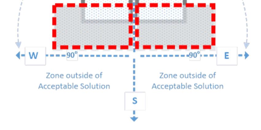
D2 For applying AS/NZS 3500.4, the references in clauses 6.5.1.2 and 6.5.1.2A(a) of the standard to ‘45°’
is taken to be a reference to ‘90°’.
Notes:
1 Clauses 6.5.1.2 and 6.5.1.2A(a) provide that collectors must be installed so they face no more than 45° east or west of true
north.
2 Under D2 orientation of a collector panel for a solar heated water system will comply with the deemed-to-satisfy solution
requirement if it is installed within 90° east or west of true north. Refer to Figure 1.
Version 1: 2019
Page 13 of 25Queensland Plumbing and Wastewater Code
Figure 1 - Orientation of collectors
Part B3 Non Drinking Water Services
Refer to Part B3 of the Plumbing Code of Australia.
Part B4 Fire-Fighting Water Services
Refer to Part B4 of the Plumbing Code of Australia and the Building Act 1975.
Part B5 Cross-Connection Control
Refer to Part B5 of the Plumbing Code of Australia.
Part B6 Rainwater Harvesting and Use
Refer to Part B6 of the Plumbing Code of Australia.
Version 1: 2019
Page 14 of 25Queensland Plumbing and Wastewater Code
Section C – Sanitary Plumbing and Drainage Systems
Part C1 Sanitary Plumbing Systems
C1.0 Scope
This Part sets out the additional requirements to the PCA for the design, construction, installation,
replacement, repair, alteration and maintenance of any part of a sanitary plumbing system of a property
including from sanitary fixtures and appliances to an approved disposal system.
Objective
CO1 The objective of this part is to:
(a) safeguard people from illness, injury or loss (including loss of amenity) due to the failure of a sanitary
plumbing installation; and
(b) ensure that a sanitary plumbing installation (including an installation provided for use by people with a
disability) is suitable; and
(c) conserve water and energy; and
(d) safeguard the environment; and
(e) safeguard public and private infrastructure; and
(f) ensure that a sanitary plumbing installation is designed and is capable of being maintained so that
throughout its serviceable life it will continue to satisfy objectives (a) to (e).
Functional statements
CF1.1 Sanitary fixtures and sanitary appliances must be provided with an adequate disposal system.
Part C2 Sanitary Drainage Systems
C2.0 Scope
This Part sets out the additional requirements for the design, construction, installation, replacement,
repair, alteration and maintenance of any part of a sanitary drainage system of a property including from
sanitary fixtures and appliances to an approved disposal system.
Objective
CO2 The objective of this part is to:
(a) safeguard people from illness, injury or loss (including loss of amenity) due to the failure of a sanitary
drainage installation; and
(b) ensure that a sanitary drainage installation (including an installation provided for use by people with a
disability) is suitable; and
(c) conserve water and energy; and
(d) safeguard the environment; and
(e) safeguard public and private infrastructure; and
(f) ensure that a sanitary drainage installation is designed and is capable of being maintained so that
throughout its serviceable life it will continue to satisfy objectives (a) to (e).
Functional statements
CF2.1 Sanitary fixtures and sanitary appliances must be provided with an adequate disposal system that
does not impact adversely on occupants of the premises, property, the environment or the sewerage
service provider’s infrastructure.
Version 1: 2019
Page 15 of 25Queensland Plumbing and Wastewater Code
C2.1 Building sanitary drain to sewerage system standard
Performance requirements
P1 Sanitary drainage for premises or premises group must provide efficient drainage for the premises or
premises group.
Deemed-to-satisfy solutions
D1 The design and installation of a main line of a sanitary drain servicing premises or a premises group
must comply with:
(a) AS/NZS 3500.2; or
(b) design requirements for sewer infrastructure published by the Local Government or sewerage service
provider for the area.
In this section:
premises group includes a proposed premises group.
main line: means a drain that provides connection points for multiple buildings but doesn’t include main
drains or branch drains of a single premises.
Note:
1. A main line of a sanitary drain servicing premises or a premises group is not the property of the sewerage service provider.
Sewerage service providers are not responsible for the maintenance of a main line upstream from the connection point to
the sewerage service provider’s sewer main.
C2.2 Connection of appliances and fixtures to grease arrestors
Performance requirements
P1 The connection of an appliance or fixture used in a commercial premises that has the potential to
discharge greasy waste to a sewerage system must be connected in such a way as to prevent greasy
waste entering the sewer.
Deemed-to-satisfy solutions
D1 Any appliance or fixture installed in a commercial premises that may discharge greasy waste must
connect to the sewerage system through a grease arrestor.
D2 An appliance or fixture discharging to a grease arrestor must be:
(a) fitted with a fixture trap; and
(b) vented in a way that is compliant with AS/NZS 3500.2.
D3 If the grease arrestor will collect greasy waste from floor areas, a 100mm floor waste must be
connected to the inlet pipe of the arrestor.
D4 If the distance between a fixture and a grease arrestor is greater than 2.5m the diameter of the
connecting pipe must be greater than 50mm.
C2.3 Requirements for grease arrestors
Performance requirements
P1 Grease arrestors must be:
(a) located in an accessible location; and
(b) designed, constructed and installed to –
(i) avoid the likelihood of greasy waste entering the sewerage system; and
(ii) prevent foul air or odours; and
(iii) avoid illness, injury and loss to people.
Version 1: 2019
Page 16 of 25Queensland Plumbing and Wastewater Code
Deemed-to-satisfy solutions
D1 A grease arrestor must:
(a) be of a size and design approved:
(i) for premises in a sewered area—by the sewerage service provider, or
(ii) for any other premises—by the local government;
(b) be installed:
(i) in an accessible position to enable servicing;
(ii) preferably outside a building; and
(iii) as close as practicable to the appliance or fixtures the arrestor serves.
(c) have a gas-tight lid suitable for loads likely to be imposed.
D2 The grease arrestor outlet must:
(a) have a minimum diameter of 100mm; and
(b) be fitted with a trap.
D3 Grease arrestors must have a:
(a) 100mm vent that complies with AS/NZS 3500.2 section 6.9 and is installed at the upper end of a drain
that connects to the grease arrestor; and
(b) 100mm vent that complies with AS/NZS 3500.2 section 6.9 and is directly connected to the chamber.
D4 The clean-out point for a grease arrestor must be accessible.
C2.4 Vent pipes to be covered
Performance requirements
P1 A vent pipe must terminate at the upper end of a sanitary drain or sanitary plumbing installation in a
manner that prevents the egress or ingress of animals, vermin or insects whilst still ensuring sufficient
ventilation of the sanitary drainage system.
Deemed-to-satisfy solutions
D1 A vent pipe must have a vent cowl over the termination point of the vent pipe that has the same
effective ventilation capacity as the vent pipe.
D2 If the vent pipe is connected to an on-site sewage facility, the vent cowl must be mosquito proof.
Section D – Excessive Noise
Refer to Section D of the Plumbing Code of Australia.
Section E – Facilities
Refer to Section E of the Plumbing Code of Australia.
Version 1: 2019
Page 17 of 25Queensland Plumbing and Wastewater Code
Section F1 – On-site Wastewater Management Systems
Part F1 On-site Wastewater Management Systems
F1.0 Scope
This Part sets out additional requirements to the PCA for the design, construction, installation,
replacement, repair, alteration and maintenance of any part of an on-site wastewater management
system.
Objective
FO1 The objective of this Part is to:
(a) safeguard people from illness, injury or loss (including loss of amenity) due to the failure of an on-site
wastewater management system installation; and
(b) ensure that an on-site wastewater management system installation (including an installation provided
for use by people with a disability) is suitable; and
(c) conserve water and energy; and
(d) safeguard the environment; and
(e) safeguard public and private infrastructure; and
(f) ensure that an on-site wastewater management system installation is designed and is capable of
being maintained so that throughout its serviceable life it will continue to satisfy objectives (a) to (e).
Functional statements
On-site wastewater management systems must collect, contain, treat and assimilate and process
domestic-wastewater, human excreta, or both so that public health and environmental standards are
maintained.
F1.1 On-site Wastewater Management Systems
Performance requirements
P1 On-site wastewater management systems must be designed, constructed, installed and maintained:
(a) to protect public health by ensuring that risks associated with the dispersal of wastewater to a land
application area are minimised; and
(b) to protect the environment by ensuring:
(i) surface, ground water and waterways are not polluted; and
(ii) soil productivity is maintained or enhanced; and
(c) with adequate treatment and storage capacity for the volume of waste and frequency of disposal;
(d) with adequate size, strength and rigidity for the nature, flow rates, volume of wastes and/or waste
products which must be processed;
(e) with adequate vehicle access for collection of waste from the facility;
(f) to avoid the likelihood of contamination of any drinking water supplies;
(g) from materials which are impervious both to the waste for which disposal is required and to water;
(h) to avoid the likelihood of foul air and gases accumulating within or entering into buildings or nearby
premises;
(i) to avoid the likelihood of unauthorised access;
(j) to permit cleaning, maintenance, measurement and performance sampling;
(k) to avoid the likelihood of surface water and stormwater entering the system;
(l) to avoid the likelihood of unintended or uncontrolled discharge;
(m) to permit the manufacturer, model, serial number and design capacity to be easily identifiable after
installation;
(n) to minimise nuisance (e.g. noise) to the occupants of nearby premises; and
(o) so that the installation throughout its design life will continue to satisfy the requirements of items
(a) to (n).
Version 1: 2019
Page 18 of 25Queensland Plumbing and Wastewater Code
Deemed-to-satisfy solutions
D1 Wastewater must be disposed of in a land application area which complies with F1.3.
D2 Septic tanks must comply with AS/NZS 1546.1.
D3 The design, commissioning, performance and compliance testing of a secondary treatment plant must
be in accordance with AS 1546.3.
D4 An on-site wastewater management system must be operated and maintained in accordance with the
designer’s or manufacturer’s instructions.
D5 The size, determination, design, construction, installation, replacement, repair, alteration and
maintenance of on-site wastewater management systems and land application area must be in
accordance with AS/NZS 1547.
D6 The design, construction, installation, replacement, repair, alteration and maintenance of all sanitary
plumbing and drainage for an on-site wastewater management system must be in accordance with
AS/NZS 3500.2.
F1.2 Greywater Use Facility
Performance requirements
P1 A greywater use facility must be designed, constructed, installed and maintained:
(a) to protect public health by ensuring that risks associated with the use and/or disposal of greywater to
the land application area are minimised; and
(b) protect the environment by ensuring:
(i) surface, ground water and waterways are not polluted; and
(ii) soil productivity is maintained or enhanced.
(c) with adequate treatment and storage capacity for the volume of waste and frequency of disposal;
(d) with adequate size, strength and rigidity for the nature, flow rates, volume of wastes and/or waste
products which must be processed;
(e) with adequate vehicle access for collection of waste from the facility;
(f) to avoid the likelihood of contamination of any drinking water supplies;
(g) from materials which are impervious both to the waste for which disposal is required and to water;
(h) to avoid the likelihood of foul air and gases accumulating within or entering into buildings or nearby
premises;
(i) to avoid the likelihood of unauthorised access;
(j) to permit cleaning, maintenance, measurement and performance sampling;
(k) to avoid the likelihood of surface water and stormwater entering the system;
(l) to avoid the likelihood of unintended or uncontrolled discharge;
(m) to permit the manufacturer, model, serial number and designed capacity to be reasonably easily
identifiable after installation;
(n) to minimise nuisance (e.g. noise) to the occupants of nearby premises; and
(o) so that the installation throughout its design life will continue to satisfy the requirements of items
(a) to (n).
Deemed-to-satisfy solutions
D1 Greywater that is treated in a closed loop greywater treatment system must be used for the purpose,
and comply with the requirements, set out in Table T1.
D2 The design, commissioning, installation, performance and compliance testing of a greywater treatment
plant, other than a closed loop greywater treatment system, must be in accordance with AS/NZS 1546.4.
D3 Disposal of greywater to a land application area must comply with F1.3 of the QPW code.
Version 1: 2019
Page 19 of 25Queensland Plumbing and Wastewater Code
D4 The greywater use facility must be operated and maintained in accordance with the designer’s or
manufacturer’s instructions.
D5 The design, construction, installation, replacement, repair, alteration and maintenance of all sanitary
plumbing and drainage systems for a greywater use facility must be in accordance with AS/NZS 3500.
D6 All work for a greywater treatment plant must comply with the treatment plant approval.
F1.3 Land application area
Performance requirements
P1 A land application area must be designed, constructed, installed and maintained in such a manner as
to:
(a) complete the treatment, uptake and absorption of the final effluent within the boundaries of the
approved application area;
(b) avoid the likelihood of the creation of unpleasant odours or the accumulation of offensive matter;
(c) avoid the likelihood of the ingress of effluent, foul air or gases entering buildings or nearby premises;
(d) avoid the likelihood of stormwater run-off entering the pipes;
(e) avoid the likelihood of root penetration or ingress of ground water entering the pipes;
(f) protect against internal contamination;
(g) provide adequate access for maintenance;
(h) incorporate adequate provisions for effective cleaning;
(i) avoid the likelihood of unintended or uncontrolled discharge;
(j) avoid the likelihood of blockage and leakage;
(k) avoid the likelihood of damage from superimposed loads or ground movement;
(l) avoid the likelihood of contamination of any drinking water supplies;
(m) avoid the likelihood of contamination of soils, ground water and waterways; and
(n) ensure that the installation throughout its design life will continue to satisfy the requirements of items
(a) to (n).
Deemed-to-satisfy solutions
D1 The design of a land application area must take into account a site and soil evaluation report produced
as a result of an on-site inspection carried out in accordance with AS/NZS 1547.
D2 The complies with the setback distances set out in Part 2 of the Appendix and AS/NZS 1547 land
application area.
D3 The design of a land application area for a greywater treatment plant must be based on a design flow
of 100L per person per day.
D4 The land application area and any pump or motor are not located adjacent to bedrooms, living rooms
or recreational areas of the premises or nearby premises.
Version 1: 2019
Page 20 of 25Queensland Plumbing and Wastewater Code
F1.4 Composting, chemical and incinerating toilets
Performance requirements
P1 Composting, chemical, and incinerating toilets must be designed, constructed, installed and
maintained in such a manner as to:
(a) protect public health by ensuring that risks associated with the dispersal of waste are minimised; and
(b) protect the environment by ensuring:
(i) surface and ground water are not polluted; and
(ii) soil productivity is maintained or enhanced.
Deemed-to-satisfy solutions - General
D1 Composting, chemical, and incinerating toilets must be designed, constructed, maintained and
installed:
(a) with adequate storage capacity for the volume of waste and frequency of treatment of solids; and
(b) with adequate ventilation in the entire structure and chamber; and
(c) with as much natural lighting in the entire structure as possible; and
(d) to avoid untreated waste coming into contact with any person, or spill from it, when it is being
operated, maintained, removed or cleaned; and
(e) to allow all waste liquids or spills to be contained and trapped, to prevent the liquids or spills being
released outside the chamber when it is being operated, maintained, removed or cleaned; and
(f) to withstand adverse effects from the environment including, for example, by heat, cold, humidity,
gasses or sunlight; and
(g) to ensure the entire structure or the chamber and any associated inspection and access covers
and/or extensions are integrally sound, and exclude penetration by roots, and entry or infiltration of
rain, groundwater, insects and vermin; and
(h) to avoid the likelihood of a child falling through the pedestal opening; and
(i) is finished in a way that provides a smooth surface internally and externally and free of recesses; and
(j) to allow access when it is being maintained, contents removed or cleaned; and
(k) to reduce the likelihood of unauthorised access by people; and
(l) to ensure its controls and working parts are easily used and can’t be accidentally disturbed; and
(m) from materials which are durable and capable of withstanding normal operating conditions for the
design life of the facility.
D2 The structure of a toilet must comply with the minimum floor dimensions and minimum useable floor
area set out in the Building Code of Australia.
D3 The toilet door must be:
(a) constructed from a material that is impervious, opaque, impact and corrosion resistant and washable;
and
(b) fitted to ensure privacy; and
(c) able to be latched closed from the inside and outside.
D4 The toilet must have a toilet seat.
Deemed-to-satisfy solutions – composting toilets
D5 The size, determination, design and installation of waterless composting toilets must be in accordance
with AS/NZS 1546.2.
Version 1: 2019
Page 21 of 25Queensland Plumbing and Wastewater Code
Deemed-to-satisfy solutions – chemical toilets
D6 The chamber for a chemical toilet must:
(a) be designed in a way that ensures it will remain structurally sound when lifted, hoisted or transported,
including when the toilet is full; and
(b) if it is a freestanding unit, be fitted with suitable lifting loops or points to facilitate loading and off-
loading from a delivery vehicle; and
(c) if it is a freestanding unit, be anchored against ground movement or seismic loads.
D7 The chamber floor for a chemical toilet must be:
(a) constructed from a material that is impervious, impact and corrosion resistant and washable; and
(b) unbroken and slip resistant; and
(c) raised above ground level and resist lateral and uplift loads.
D8 The chamber roof for a chemical toilet must be:
(a) constructed from a material that is impervious, translucent, impact and corrosion resistant and
washable.
D9 A chemical toilet must:
(a) not include straight-drop or recirculation of contaminated material; and
(b) be fitted with a water seal bowl incorporating a counterbalanced flap arrangement that, when closed, is
capable of holding a minimal water seal.
D10 The waste holding tank for a chemical toilet must:
(a) be moulded in one piece from impervious and impact and corrosion resistant material; and
(b) have a minimum capacity of 230L; and
(c) have a suitable draw-off point through which the waste holding tank is emptied with a device to enable
emptying of the tank without spillage; and
(d) have a draw-off point that is secured so that it can’t be tampered with or opened by a person, other
than a person authorised by the local government for the area in which the toilet is located.
D11 If a chemical toilet includes a urinal, the urinal must be:
(a) suitably trapped into the waste holding tank; and
(b) capable of being flushed with non-drinking water.
D12 If a chemical toilet has a flushing mechanism, it must be:
(a) effective; and
(b) watertight; and
(c) of durable quality; and
(d) capable of providing a minimum of 200mL for each flush.
D13 If a chemical toilet includes a non-drinking water tank it must be not less than 20% of the volume of
the toilet’s waste holding tank.
D14 If the chemical toilet water tank is connected directly to a water supply it must be constructed with a
reticulation that provides a 40mm air break between the top water level and the water inlet.
Version 1: 2019
Page 22 of 25Queensland Plumbing and Wastewater Code
Deemed-to-satisfy solutions – incinerating toilets
D15 The incinerating toilet must be designed and installed in a way that ensures during the incineration
cycle or normal operation:
(a) it is fitted with an automatic safety valve to stop incineration; and
(b) the flue effluents are free from particulate matter; and
(c) the flue effluents are free from faecal and urine odours; and
(d) the flue pipe does not block the flue ways; and
(e) after it is installed it is obvious when the burner is alight; and
(f) ash removal tray is easy to remove and clean; and
(g) the handles or knobs or parts that are removable, including, for example, the ash removal tray, to
ensure a person removing the part has minimal contact with hot surfaces; and
(h) the incineration cycle does not alter the function of any components of the toilet or cause permanent
deterioration of the toilet’s surface finishes or surroundings; and
(i) the waste deposited onto the burning grid is reduced to ash in one firing cycle; and
(j) it must be capable of maintaining a CO/CO² ratio of less than 0.02; and
(k) if the burning cycle is interrupted, the toilet is capable of beginning a further completing burning cycle
when the lid is closed; and
(l) sufficient inlet air is available to achieve efficient and effective combustion.
D16 If the incinerating toilet uses gas, it must be fitted with:
(a) a way of testing the gas pressure; and
(b) a cut-off switch that cuts off the gas supply when the pressure is more than the capacity for which the
toilet has been designed; and
(c) a flame safeguard system; and
(d) a pilot turn-off provision; and
(e) a manual shut-off valve that is upstream from the other controls on the pilot and main burner lines; and
(f) fitted with a built-in draught diverter; and
(g) its burner and ignition systems and bleed line terminations must be protected against heat damage;
and
(h) its burner and ignition systems must be interlocked with the lid in a way that ensures the interlock
system cannot be bypassed; and
(i) its burner and ignition systems and sensing devices must be fitted in a way that ensures they are
stable.
D17 Any insulation material in an incinerating toilet must:
(a) be fixed in a way that ensures it can’t slip or become dislodged from the toilet; and
(b) not contain asbestos; and
(c) be odour and fume free; and
(d) not be reactive to the application for which it is being used.
Version 1: 2019
Page 23 of 25Queensland Plumbing and Wastewater Code
Appendix
Part 1 – Closed loop greywater treatment systems
Table T1 – End uses of greywater where a closed loop greywater treatment system is installed on
premises
End use Parameter Effluent compliance value
End uses in closed loop Escherichia coli (maximum) 10 cfu/100ml in any single sample. Less
greywater treatment system than 1cfu/100ml in any follow-up sample
with little or no human contact
for use in a washing machine
Note: Total dissolved solids, oil and grease and total suspended solids effluent compliance values for the operational
functionality of the system may be conditioned as part of the approval.
Part 2 – Setback Distances
Table T2 – Setback distances for subsurface land application area for a greywater treatment plant
or an on-site sewage treatment plant
Feature Horizontal separation distance
Up slope Down slope Level
Property boundaries, pedestrian paths, walkways, recreation 2 4 2
areas, retaining wall, and footings for buildings and other
structures.
Inground swimming pools 6 6 6
Inground potable water tank not exposed to primary effluent 6 6 6
Inground potable water tank exposed to primary effluent 15 15 15
Distances are given in metres and are measured from the edge of trench/bed excavation or subsurface irrigation
distribution pipework to the nearest point of the feature
Table T3 –Setback distances for surface irrigated land application area for a greywater treatment
plant or an on-site sewage treatment plant
Feature Horizontal separation distance
Property boundaries, pedestrian paths and walkways 2
Water edge of a swimming pool 6
Dwellings, recreation areas 10
Distances are given in metres and are measured from the edge of the irrigated wetted area to any point of the
feature.
Version 1: 2019
Page 24 of 25Queensland Plumbing and Wastewater Code
Table T4 - Setback distances from area affected by greywater diversion device
Feature Setback distance
Property boundaries, pedestrian paths, and driveways 1.0
Footings of buildings 1.5
Retaining wall footing 1.0
In ground swimming pool surrounds 1.0
In ground potable water tank 6.0
Bore or a dam 50
Distances are given in metres and are measured from the edge of the irrigated wetted area to any point of the
feature.
Table T5 - Setback distances for on-site sewerage facilities and greywater use facilities -
Protection of surface water and groundwater.
Feature Separation distance
For onsite – see Table 2.1 in AS 1546.3 Advanced Secondary Primary
Secondary
For greywater – see Table 2.1 in AS 1546.4 Level 1 and Level 3 Untreated
Level 2
Top of bank of permanent water course
Top of bank of intermittent water course
Top of bank of a lake, bay or estuary
Top water level of a surface water source used for agriculture, 10 30 50
aquaculture or stock purposes
Open stormwater drainage channel or drain
Bore or a dam
Unsaturated soil depth to a permanent water table (vertically) 0.3 0.6 1.2
Distances are given in metres and are measured from the edge of the irrigated wetted area to any point of the
feature.
Note: Primary effluent typically has a (BOD⁵) (Biochemical Oxygen Demand) of between 120 -240 mg/L and Total
Suspended Solids of between 65 -180 mg/L.
Version 1: 2019
Page 25 of 25You can also read