TAC Lighting Control Catalogue - Issue: May 2009
←
→
Page content transcription
If your browser does not render page correctly, please read the page content below

TAC Lighting Control
Catalogue
Issue: May 2009

More than just Lighting Control
                                           TAC LIGHTING SOLUTIONS GIVES YOU MORE THAN JUST LIGHT CONTROL
                                           Lighting Control Solutions, delivered as part of an integrated building management
                                           system from TAC, are a key tool in controlling energy use inside your buildings.
                                           A lighting control system allows for flexibility in the utilisation of internal space.
                                           Regular and rapid changes in the use of buildings, and increasing expectations
                                           regarding comfort and performance, mean that lighting installations must be able to
                                           evolve to meet the requirements of an expanding business, or be easily adapted to
                                           suit new tenants.
                                           Lighting Solutions from TAC and its partners meet the needs of building users and
                                           owners by:
                                           • reducing installation and operating costs
                                           • providing greater flexibility in the use of building space
                                           • helping building owners meet legal and building performance regulations.

                                           Global Leader in Building IT
                                           TAC is a leading provider of building automation solutions based on Open Integrated
                                           Systems for Building IT. TAC’s mission is to provide added value through building
                                           environment services for indoor climate, security and use of energy, delivered with
                                           advanced technology to end users and property owners throughout the world.
                                           With over 80 years of experience in the HVAC, building automation and security
                                           arenas, TAC employs more than 8,000 people worldwide, with partners and branches
                                           in 80 countries. TAC’s parent company, Schneider Electric, is the global specialist
                                           in energy management with 120,000 employees worldwide and operations in
                                           102 countries.
                                           For further details of the products featured in this catalogue, consult the relevant
                                           documentation on the TAC extranet, ExchangeOnline at http://extranet.tac.com/
                                           (registration requirement applies) or contact your local TAC sales office.

                                                                                www.tac.com

2   Lighting Control Solutions – Introduction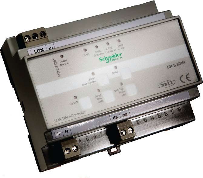
Table of Contents
 INTRODUCTION                                     4

TAC Lighting Control Solutions                    5
Automating energy efficiency                      6
Design Programme                                  8
Room Control Unit                                 9
LON I/O Modules                                  10
DALI Controller                                  12
DALI Gateway                                     13
Multisensors                                     14
Temperature Control                              15

 PRODUCT SECTION 1, Schneider badged             16

System Components                                16
Panels                                           17
Digital output                                   19
Sunblind                                         19
DALI Controller                                  20
DALI Multi-Sensors                               20
Dimmer Output                                    21
Digital Inputs                                   22
Occupancy/Motion Detectors                       22

 PRODUCT SECTION 2, SVEA/Merten badged           24
System Components                                24
Panels                                           24
Occupancy/Motion Detectors                       27
Digital Inputs                                   28
Digital Outputs                                  29
Combined In-/Outputs                             29
Sunblind                                         31
DALI Controller/Gateway                          32
Physical Sensors                                 33

Lighting Control Solutions – Table of Contents        3

Buildings evolve and are transformed           • S tandardised and easily comprehensible
                                           over decades. They need flexible systems          operation of the facilities
                                           that are designed to adapt to changing         • Reduction of maintenance and
                                           technologies and user demands. That is           service costs
                                           why the choice of a commmunications
                                           bus system such as LON is of such              Planners and Installers:
                                           long-term importance.                          • Prevention of installation and planning
                                                                                             mistakes thanks to an easy and
                                           LON-based building management
                                                                                             comprehensible installation procedure
                                           systems provide tremendous advantages
                                                                                          • Lower installation costs, in comparison
                                           to everyone involved:
                                                                                             to isolated solutions
                                           Architects:                                    • Facilitates compliance with regulations
                                           • The technical demands on building              by reducing the risk of fire
                                              systems can be satisfied in a simpler,      • Reduced production costs due to
                                              more flexible and cost-effective way.          the multiple use of sensors and the
                                           • Control and display devices with bus           elimination of expensive gateway
                                              capability combine all the functions of        solutions for data exchange between
                                              the different installation systems and at      individual systems
                                              the same time provide a visually            • Reduced training costs
                                              appealing design.
                                           Builders and Operators:
                                           • A cost-effective installation
                                           • A high degree of flexibility, and
                                              financial savings, when the installation
                                              needs to be retrofitted or modified
                                           • Reduction of operating costs by
                                              intelligent facility management
                                           • “ Transparency” of buildings by
                                              centralised annunciation, control
                                              and monitoring

4   Lighting Control Solutions – Introduction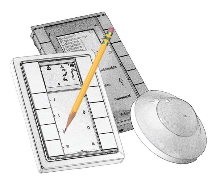
TAC Lighting
Control Solutions
APPLICATIONS
The use of an intelligent building system is particularly recommended for
buildings which require an optimised installation in terms of maximum
flexibility and comfort, combined with minimum additional cabling, e. g.
in banks and building societies, office and administration buildings,
hospitals, hotels, department stores, industrial warehouses, schools etc.
Light and sunblind control is a important part of the system as it represents
a major part of the potential energy savings.

LIGHT CONTROL
Lighting units may be controlled both centrally and locally. The light can
be dimmed or switched at predetermined times. In addition, it can be made
dependent on indoor or outdoor brightness levels and whether the building
– or a given area of the building – is currently occupied or not, so that the
presence or absence of building users so that energy and operating costs
are reduced.
Scene control provides the opportunity to store brightness levels, and of
retrieving the settings via push buttons or an IR remote control as often as
required, making it possible to operate any lighting scene within seconds.

SUNBLIND CONTROL
Sunblinds can similarly be controlled both centrally and locally. Wind,
rainfall and temperature sensors detect the weather conditions,
and drive the outdoor venetian blinds automatically into a safe position
if required. Via scene control, the sunblinds can adopt a preset position
with one key press. The automatic panel adjustment function calculates
the current sun position depending on date, time and location of the
building, and adjusts the panels in such a way that optimum transparency
and antiglare protection are provided at any time. In addition, sunblind
control can be combined with HVAC control. According to the incident
solar radiation and the particular room temperature, the blinds are lowered
to avoid overheating.

Lighting Control Solutions – Introduction                                       5
Automating energy efficiency

There are different possibilities to equip buildings so that            PRESENCE-DEPENDENT LIGHTING CONTROL
they can be run in an energy-saving manner. Building                    This function is used to save lighting energy in areas with
automation, and especially room automation, offers                      insufficient daylight. The saving effect is achieved having
high energy saving potential.                                           the lighting controlled by presence/ movement detectors,
                                                                        which only turn on the lighting when the room is occupied.
FUNCTIONS FOR SAVING LIGHTING ENERGY                                    The saving potential depends, therefore, primarily on the
The functions for saving lighting energy avoid unnecessary              level of use.
use of artificial lighting and thus save electricity. They are
based mainly on the room conditions ”level of light in room”            SUNBLIND CONTROLLED BY THE POSITION OF THE SUN
and ”presence”.                                                         (SUN AUTOMATIC SYSTEM)
CONSTANT LIGHT CONTROL                                                  Controlling the sunblind according to the position of the sun
                                                                        (also known as the sun automatic system) ensures that the
Multi-function sensors determine the brightness of the room
                                                                        sunblind automatically moves to a defined shield position when
and whether it is occupied. They transmit their data to dimmer
                                                                        strong solar radiation is present. As soon as the intensity of the
actuators. If the room is not being used, the lighting stays off. If
                                                                        sunshine lessens, it is moved back. The savings are attributable
the room is being used, the dimmer actuators adjust the lighting
                                                                        particularly to the fact that automatic control is more effective
to a precisely defined level of brightness. The energy savings are
                                                                        than manual control. This reduces the need for artificial light.
especially high if the room is well supplied with daylight, or if its
                                                                        The savings potential is between 5 and 8 percent.
use requires a high level of lighting. The savings potential
is between 35 and 50 percent.
                                                                        SLAT TRACKING
BRIGHTNESS-DEPENDENT LIGHTING CONTROL                                   The “slat tracking” function ensures that the sunblind slats
This function basically corresponds to constant light control.          automatically adjust to the position of the sun. In this way,
Since switchable light actuators are used instead of dimmer             the diffuse daylight that shines through the blinds can be
actuators, the lighting level cannot be exactly set to the              used. At the same time, the proportion of artificial light can be
minimum level. For that reason, the energy savings potential is         reduced, the “slat tracking” function makes lighting energy
about 10 percent less than for constant light control, and is no        savings of 10 to 13 percent possible.
higher than 45 percent.

6     Lighting Control Solutions – Automating energy efficiency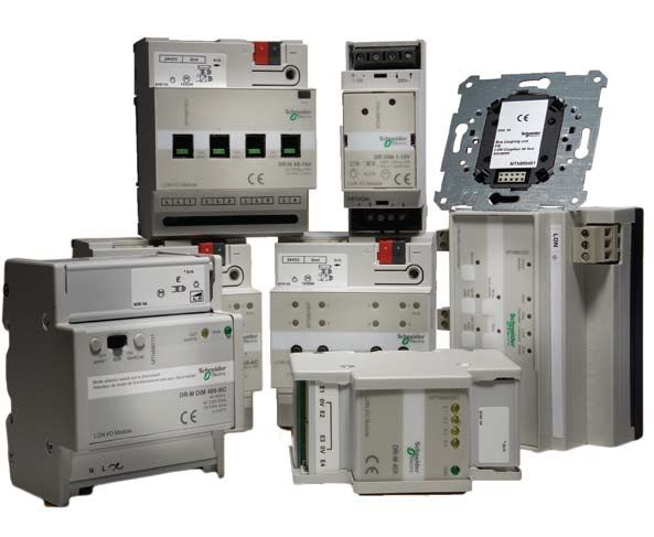
INTERACTION BETWEEN SLAT TRACKING                                       Planning and configuration of an
AND CONSTANT LIGHT CONTROL                                              energy saving room automation system
An integrated system permits functions such as slat tracking and        The planning and configuration of an energy saving room
constant light control to be used together and in coordination.         automation system is simplified by the fact that the room
This combination is especially advisable in rooms with a good           automation system functions conform to the Lonmark profiles
supply of daylight. The savings here can be up to 30 percent.           used around the world. With this system, room automation
                                                                        functions can be described clearly and comprehensively.
INTEGRATED ROOM AUTOMATION SYSTEM
                                                                        Once the desired room automation functions have been
A precondition for the optimal effectiveness of all functions is        selected, the savings potential of the particular room
an integrated room automation system, in which the different            automation solution can be determined, and the chosen
systems such as heating, cooling or glare shield work in unison.        solution can be configured with devices.
In an integrated room automation system, the sensors provide
the information for all the systems, while actuators and the
lighting, heating, and cooling systems, provide simultaneous
support.

 Functions for saving lighting energy
            Room Automation Functions                              Savings                                  Positive factors

                                                                                                         - good daylight supply
               Constant light control
                                                                   35 - 50%                         - high lighting levels (>300lux)
          (presence-dependent, dimmed)
                                                                                                - particularly efficient with slat control

    Presence and brightness-dependent lighting                                                          - good daylight supply
                                                                   25 - 45%
                control (switched)                                                                        - high lighting levels

         Automatic sun protection system                            5 - 8%                              - good daylight supply

                                                                                                         - good daylight supply
                  Slat adjustment                                  10 - 13%
                                                                                           - particularly efficient with constant light control

       Automatic lighting or staircase lighting              No information                      - low presence levels (e.g. corridors)

Lighting Control Solutions – Automating energy efficiency                                                                                         7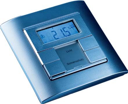
Design Programme

Open building control systems provide      We offer a range of aesthetically
synergy effects between the individual     appealing products including System-M.
systems. The functions of various
                                           System-M comprises ten modules –
individual installation systems are
                                           from a 1-gang push button to occupancy
combined in one device. Previous light
                                           detector. Each is available in five colours.
switches, thermostats and sunblind
                                           These modules can be combined with
controls of different sizes, designs and
                                           27 different frames.
colours are replaced by a single control
and display device, by means of which      The ARTEC Program is timeless in
all the room functions mentioned can       design, with a clean, flush-fitting profile.
be controlled.                             It satisfies the demands of modern
                                           architecture, and is suitable for many
LON-interfaced Control Panels combine
                                           different locations. Its premium stainless
the performance capability of LON a
                                           steel design provides the ideal surface for
timeless, unobtrusive design. Clearly
                                           subtle but highly visible lettering.
arranged keys, lettering areas and
displays, allow the user to control
the lighting, venetian blinds, heating,
ventilation and other devices in the
room effortlessly.

8    Lighting Control Solutions – Design Programme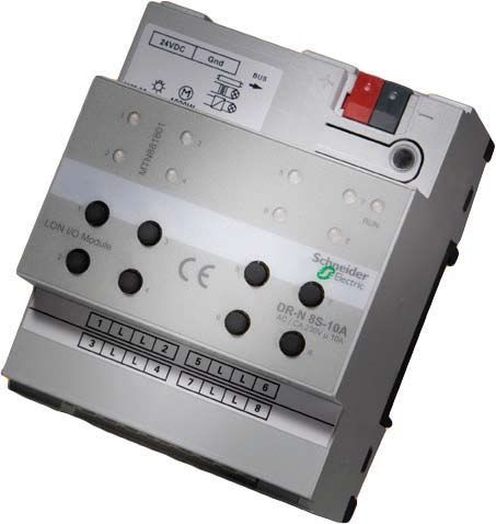
Room Control Unit

Room Control Units RCU-61 and RCU-           In addition, Room Control Unit RCU-101
101 are a combination of a temperature       can be activated by a remote control
controller and a multi-function push         device which is available separately
button with display. The RCU-61              All design modules consist of application
includes six, and the RCU-101 ten, large     modules, frame and LON BUS Coupling
push buttons; either can be adapted to       Unit. (the “LON-BCU®”).
different individual functions.
                                             The LON-BCU is available individually
Two push buttons each are reserved for       for the use of EIB-application modules in
temperature control.                         LON networks such as
The Room Control Units can control           • Push Buttons
any operating resource installed in a        • Temperature Controllers
room, either individually or in scenes,      • Motion detectors
by a single device:                          from the product ranges of manufacturers
• Lighting and sunblinds                     such as Berker, Feller, Gira, Jung, Merten
• Heating, air conditioning                 and Siemens.
  and ventilation                            Besides a broad variety of application
                                             modules, our third generation of LON
                                             Bus Coupling Units features low power
                                             consumption. It utilises link power
                                             technology, taking the power needed
                                             to operate from the LON network.
                                             No additional power supply is required.
                                             As with the standard modules,
                                             configuration is made with an LNS
                                             plug-in. All applications comply with
                                             the relevant LonMark standards.

Lighting Control Solutions – Room Control Unit                                            9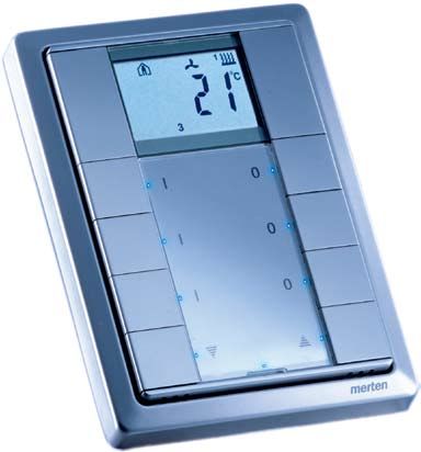
LON I/O Modules

TAC Lighting Control Solutions cover         This provides protection against polarity   The “DR-N” product line is the latest
a wide range of functions, including         reversal – should the device be replaced    generation of I/O modules with the
• Digital Inputs for 24 V and 230 V input   – and against accidental contact at         following features:
   voltage, and for floating contacts        any time.                                   • Bus connection via 2-pin bus terminal
• Analog inputs and outputs                                                                with protective cap
                                             Clamp-type terminals allow up to four
• Switching actuators with 24 V                                                         • Pluggable screw-type terminals for
                                             bus cables to be connected to the device,
   semiconductor outputs                                                                    inputs and outputs
                                             so that the line is not interrupted if a
• Switching actuators with relay outputs                                                • Status LED for every input and output
                                             device is disconnected from the network.
• Phase controlled dimmers 1-10 V                                                       • Manual operation
   control devices for dimmable electronic   Power lines and bus cables may be           • Free-Topology-Transceiver (FTT)
   ballasts                                  installed without spacing. Single insu-     • DC 18...30 V supply voltage
• LON DALI-Controllers for control of       lated wires or power lines and bus          • Configurable reaction of the outputs
   electronic DALI components                cables either have to be installed with        to power-down and power-up/reset
Most of the devices are suitable for DIN     a spacing of 4 mm or they need an
                                                                                         The ”DR-M” product line consists of
rail mounting. These devices are sub-        appropriate insulation (DIN VDE 01 10-
                                                                                         about 20 I/O modules with the following
classified into the three product lines M,   1). A protective cap is included with the
                                                                                         distinctive features:
N and S.                                     REG-M and REG-N modules, by means of
                                                                                         • Bus connection via 2-pin bus
                                             which which a clear separation of power
Cables can be attached to the inputs and                                                   terminal with protective cap
                                             line and bus cable is guaranteed.
outputs of most devices in the M, N,                                                     • Pluggable screw-type terminals
and S product range by use of pluggable                                                    for inputs and outputs
screw-type terminals. They can be quickly                                                • Link Power Transceiver (LPT)
and easily replaced when the need arises.

10   Lighting Control Solutions – LON I/O Modules
Due to Link-Power-technology, both data Conventional push buttons are normally
and the supply voltage for the control connected to the digital inputs to operate
electronics can be transmitted via the the consumer loads at the outputs.
LON network. Particularly, if the I/O Apart from that, the digital inputs can
modules are applied peripherally the be used for floating contacts, e.g. of
complexity of cabling is minimised. LPT motion detectors, photo-electric lighting
devices can be operated in combination controllers, or thermostats, independently
with FTT devices in one subnet, but then of the outputs. The contact current is
they require an extra LON Power Supply approx. 10 mA. The contact voltage of
about 24 V is generated by the device
The ”DR-S” product line includes,
itself, so that no external power supply
in addition to the DALI Controllers,
unit is required. Every input status, as
four I/O modules with the following
well as the output states, is indicated by a
characteristics:
status LED. Every output can be operated
• Four resp. eight outputs and the same
manually, using the push buttons on top
number of inputs for consumer loads
of the casing.
and drives
• Status LED for every input and output All cables can be connected to the device
• Manual operation using pluggable screw-type terminals.
• Pluggable screw-type terminals The REG-S modules are some of the
• Free Topology Transceiver (FTT) few LON actuators that provide the
• 230 V supply voltage opportunity to configure the outputs’
• Configurable reaction of the outputs to reaction to power-down as well as to
power-down and power-up/reset power-up/reset.
Lighting Control Solutions – LON I/O Modules 11DALI Controller
In many fields of application, dimmable profiles. In addition, they provide the centre or via a LON TCP/IP gateway
lighting systems are becoming more scene control of the DALI devices. to any other place in the world.
and more important. The previous gap Different characteristic curves
Up to 256 devices, divided into 64 DALI
in communication existing between the of dimmable electronic ballasts from
groups, can be connected to the LON
LON network and the lamps is closed by various manufacturers are conformed
DALI Gateway REG 4x16 DIM with four
DALI. This Digital Addressable Lighting to automatically.
DALI control lines.
Interface is a standardised interface for
The LON DALI Controllers are DALI
electronic ballasts developed by the In addition to the DALI connections, the
system devices. They control all DALI
leading European manufacturers. gateway also has a LON Twisted-Pair
ballasts and connected DALI multisensors,
interface with Free Topology Transceiver,
By means of ballast addresses, the lamps and provide an interface between LON
as well as an Ethernet interface.
of up to 64 DALI ballasts can be switched and the DALI bus. By use of the familiar
and dimmed individually via a common LNS plug-in, the controllers can be The TP/FT interface is intended for
data line – without the usual brightness configured and the DALI devices can be connection of up to 64 LON control units
gradient due to the resistance of the integrated completely in the LON bus via an Ethernet interface. The LON DALI
control line. system. Neither special accessory devices, Gateway usually communicates with a
nor software, are required. superior light management or building
The DALI ballasts can be divided into
automation system by means of LON
up to 16 groups. Every ballast provides The electronic DALI ballasts communicate
over IP, via an Ethernet interface. Other
16 scene memory units for light levels bi-directionally, i.e. they can propagate
DALI Gateways are also being addressed
so particular atmospheres can be their current state to other DALI devices.
in this way.
recalled directly. In combination with the appropriate
equipment, lamps can announce failures By means of the integrated Ethernet
LON DALI Controllers DR-S 4DIM, 8DIM
to the LON DALI Controller. The latter interface, a hierarchically very even but
and 16DIM allow independent control
transmits the message via the LON powerful interface, network structure
of four, eight or 16 lighting groups
network to a building management emerges without IP-gateways.
respectively, according to the LonMark
12 Lighting Control Solutions – DALI ControllerDALI Gateway
Normally initiation is also carried out via The DALI Multisensor is a combination
an Ethernet interface. The setting of all occupancy and light sensor.
internal parameters and configurations
For the first time, a cost-effective solution
can be carried out by an LNS-
for creating an intelligent lighting control,
independent configuration tool.
as well as its integration into building
For constant light control and scene automation, is offered by LON DALI
control, all relevant LonMark objects, Controllers, respectively by a LON DALI
such as ”Lamp Actuator”, ”Constant Gateway, in combination with the DALI
Light Controller”, ”Occupancy Multi-sensor.
Controller” and ”Scene Controller” are
available freely configurable, in virtually
unlimited quantities. The common
restrictions with LON devices, for
example the limitation of 15 address table
entries, no longer exist. The LON DALI
Gateway can also be connected to the
DALI LA-11 Multisensor.
Lighting Control Solutions – DALI Gateway 13Multisensors
A demand-responsive single room control The ILA-22 multi-sensor possesses an
helps to save up to 70 percent of energy additional IR receiver. Combined with
on lighting, heating and ventilation. To the remote control, it is possible to
enable this, it is necessary, among other control scenes and sunblinds in addition
things to detect brightness and presence to dimming and switching the lighting.
in the room. The multi-sensors feature a LON inter-
face with a link-power transceiver, and
Based on passive infrared technology,
can therefore be connected directly to a
the LA-21 and ILA-22 LON multi-sensors
LON network. A further auxiliary supply
are designed for presence-dependent
is not required.
lighting control.
The multi-sensors are particularly suitable
Installed at a height of 2.5 m, these multi-
for installation in single and open-
sensors detect movement in a circular
plan offices, foyers, stairways, class-,
range of 14 m
conference- and meeting rooms.
The integrated light sensor is designed
for daylight-dependent lighting control.
Combined with the constant light
controller objects of the dimmers, the
1-10 V control outputs or the DALI
controllers, a cost-effective solution
can be achieved.
14 Lighting Control Solutions – MultisensorsTemperature Control
For single room temperature control, The following advantages result from
all sensors, actuators and the operating decentralised room control:
unit are combined with a central control • Simple and cost-effective cabling
unit in a star topography. This approach • High flexibility in case of alterations
has many disadvantages: or extensions
• Extensive cabling between • The controller is available in all
the devices versions and designs.
• Inflexibility due to fixed wiring
Besides the LON network, only a
• Additional space is required for the
temperature controller incl. LON Bus
control unit and cables
Coupling Unit, and at least one LON
• The design of the control unit does
valve actuator (or other actuator) is
not match the other switches and
required. This combination can be
sockets.
retrofitted by an occupancy sensor or
Alternatively, the following approach a system clock. Via the LON network,
can be adopted: the temperature the decentral single room control can be
sensor and the operating and control linked to other installation systems, such
unit are integrated in one bus device as lighting, sunblind or access control.
(”Temperature Controller”). The
controller transmits the manipulated
variable via the LON network to an
actuator (e. g. art. no. 62301-233)
mounted on a cooling or heating battery
in the ceiling void, which converts the
command into a corresponding valve
movement. Floating contacts, e. g. of
architrave-type switches at the windows,
or dew point sensors can be connected
directly to the digital inputs of the valve
actuator.
Lighting Control Solutions – Temperature Control 15TAC Lighting Products
Product Section 1
All the TAC Lighting products published in this catalogue are produced by Schneider Electric.
The products, including software and documentation, shown in the first section of this
publication are all entirely Schneider branded.
The products in the latter section of this catalogue are SVEA or Merten branded and will be re-
launched under the Schneider brand in due course. Please note that the SVEA/Merten branded
products are fully compatible with the Schneider branded items.
System Components
Power Supply LPS 133 • power supply for devices with Link Power Transceivers
MTN884019 • rated output current:
Available in Q2 2009
– 1 A (short-circuit- and overload-proof )
if supply voltage 85 V .. 195 V
– 1.3 A (short-circuit- and overload-proof )
if supply voltage > 195 V
• m
ax. continuous output current: 1.3 A
if supply voltage > 195 V
• bus power monitoring via relay output
• a djustable bus terminator for free or line topology
or without termination
• supply voltage: AC 120/230 V (AC 85 .. 264 V)
• DIN rail mounting according to EN 50 022
• width of device: approx. 144 mm (8 pitch)
Bus Coupling Unit UP • b
ase module for flush-mounted LON devices and interface
MTN880451 between EIB compatible application modules and LON
network
• screw fixing in flush-mounted boxes
• s oftware applications according to LonMark profile “Switch
(3200)” and “Scene Panel (3250)” to translate the signals
of the connected application modules (push buttons, motion
detectors, temperature controllers, etc.) into messages for
light, sunblind, occupancy and single room temperature
control
A list of the supported application modules can be found on ...
can be found on ExchangeOnline/Product zone/Field device
Europe/Lighting Control.
16 Lighting Control Solutions – System ComponentsPanels
LON ARTEC Push button • application module in Merten ARTEC design
1-gang • two push buttons for individually assigned functions
MTN880701 • one status LED
polar white glossy
• s oftware application according to LonMark profile “Switch
MTN880711 (3200)”, “Scene Panel (3250)” and “Occupancy Sensor
stainless steel (1060)” for light, sunblind or scene and occupancy control
To be completed with a LON Bus Coupling Unit UP
(MTN88045) and a frame in the favoured colour.
LON ARTEC Push button • application module in Merten ARTEC design
2-gang • four push buttons for individually assigned functions
MTN880721 • two status LEDs
polar white glossy
• o
ther features as per LON ARTEC Push button 1-gang
MTN880731 (art. no. MTN880701)
stainless steel
To be completed with a LON Bus Coupling Unit UP (MTN88045)
and a frame in the favoured colour.
LON ARTEC Push button • application module in Merten ARTEC design
4-gang • eight push buttons for individually assigned functions
MTN880741 • four status LEDs
polar white glossy
• o
ther features as per LON ARTEC Push button 1-gang
MTN880751 (art. no. 880701)
stainless steel
To be completed with a LON Bus Coupling Unit UP (MTN88045)
and a frame in the favoured colour.
LON ARTEC Room Control • application module with display in Merten ARTEC design
Unit RCU-61 • backlit LC display
MTN880901 • f our push buttons for individually assigned functions with
polar white glossy a status LED for each push button
MTN880911 • t wo push buttons for setpoint adjustment and configuration
stainless steel of the display functions
• c ontinuous action controller for heating and cooling incl.
integrated temperature sensor
• c alculates manipulated variables from setpoint and actual
temperature values according to the particular operation
mode
• c an control valves or switching actuators in combination
with an electro-thermal control valve
• two different setpoints for heating and cooling
• d
isplay to indicate room temperature and operation modes
as per comfort, standby, night
• degree of protection: IP 20
• s oftware application according to LonMark profile “Switch
(3200)”, “Scene Panel (3250)” and “Thermostat (8060)”
for light, sunblind or scene and room temperature control
To be completed with a LON Bus Coupling Unit UP
(MTN88045) and a frame in the favoured colour.
Lighting Control Solutions – Panels 17LON ARTEC Room • application module with display in Merten ARTEC design
Control Unit RCU-101 • e
ight push buttons for individually assigned functions with a
MTN880921 status LED for each push button
polar white glossy
• IR receiver for control of the button functions via IR Remote
MTN880931 Control
stainless steel (art. no. 42083-107)
• Piezo buzzer to indicate warnings or alarms
• o
ther features as per LON ARTEC Room Control Unit RCU-61
(art. no. MTN88090)
To be completed with a LON Bus Coupling Unit UP (MTN88045)
and a frame in the favoured colour.
Frame ARTEC 1-gang • frame 1-gang in Merten ARTEC design
MTN481119 Frames for multiple push button modules are available on
polar white glossy request.
MTN481146
stainless steel
Frame ARTEC for RCU-101 • frame for RCU-101 in Merten ARTEC design
MTN481919
polar white glossy
MTN481946
stainless steel
LON ARTEC Motion • indoor motion detector in Merten ARTEC design
Detector • detetion of movementswithin a horizontal angle of 180 degrees
MTN880971
• motion-dependent control of room functions
polar white glossy
MTN880981 • integrated and individually adjustable threshold value switch
stainless steel forbrigtness-dependent light control
• s oftware applcations to translate the detected movements
according to LonMark profile “Occupancy sensor (1060)” into
LON messages for occupancy-dependent light control and
“Occupancy controller(3071)”
•To be completed with a LON Bus Coupling Unit UP (MTN880451)
and a frame in the favoured colour.
18 Lighting Control Solutions – PanelsDigital output
I/O Module DR-N 4S-16A • independent switching of four load groups
MTN881831 • four relay outputs (N.O. contacts, 16 A)
• manual operation per output
• status signaling via manual switch
• power-down detection
• supply voltage: DC 24 V
• screw-type terminals
• width of device: approx. 72 mm (4 pitch)
• s oftware application for control of four independent
consumer loads according to LonMark profile “Lamp
Actuator (3040)” including timers, logic operation,
prioritised control and configurable reaction of the
outputs to power-up/bus reset.
In addition, four “Scene Controllers (3251)”
are available.
I/O Module DR-N 8S 10A • independent switching of eight load groups
MTN881801 • eight relay outputs (N.O. contacts, 10 A)
• manual operation and status indication per output
• power-down detection
• supply voltage: DC 24 V
• pluggable screw-type terminals
• width of device: approx. 72 mm (4 pitch)
• s oftware application for control of eight independent
consumer loads according to LonMark profile “Lamp Actuator
(3040)” including timers, logic operation, prioritised control
and configurable reaction of the outputs to power-up/bus
reset.
Two “Scene Controllers (3251)” are available.
Sunblind
I/O MODULE DR-N MSCU4-AC • c ontrol of four customary sunblinds by use of interference-
MTN881811 suppressed standard motors
• eight relay outputs (N.O. contacts, 10 A)
• manual operation and status indication per output
• power down detection
• supply voltage: DC 24 V
• pluggable screw-type terminals
• width of device: approx. 72 mm (4 pitch)
• s oftware application for control of four independent
sunblind drives. Opportunity of prioritised control, analysis
of meteorological data for sunblind protection, scene and
group control
Lighting Control Solutions – Digital output/Sunblind 19DALI Controller
DALI-Controller DR-S 8DIM • c ontrol and supply of up to 64 DALI devices, devided into up to eight
MTN887251 groups
• addressing of the DALI devices with LNS plug-in
• provides DALI supply voltage, 16 V
• status monitoring of all connected DALI devices
• monitoring of all lamps (if DALI compatible
• status LEDs for diagnostics and status indication
• manual operation for direct control of DALI devices
• DALI device replacement with manual operation
• pluggable screw-type terminals•
• supply voltage: AC 230 V
• DIN rail mounting according to EN 50 02)
• width of device: approx. 105 mm (6 pitch)
• s oftware application for control of up to 64 DALI devices,
divided into four groups including timers, prioritised control
and configurable reaction to power-down/power-up/bus reset.
Furthermore, the application provides constant light and scene
control according to LonMark profile “Lamp Actuator (3040)”,
“Constant Light Controller (3050)” and scene control in the DALI
devices
DALI Multi-Sensors
DALI Multi-Sensor LA-11 • c ombination of occupancy sensor and brightness sensor with DALI
MTN880641 interface
• s uitable for LON DALI-Controller REG-S xDIM (art. no. 36236-
128, -232, -236), DALI Gateway REG 4x16 DIM (art. no. 36236-
332) and IRC Controller REG IP-1111 (art. no. 36930-340)
• fl
ush-mounting (surface-mounting in combination with Surface
Mounting Box, art. no. 42020-106)
• c ircular sensor range with a diameter of approx. 14 m at 2.5 m
mounting height
• detection range: 360 degrees
• five detection levels with 284 control segments in 71 zones
• b
rightness sensor for daylight-dependent light control, sensor
range: 10 .. 1,000 Lux
• dimensions of surface-mounted sensor: 105 x 42.6 mm (D x H)
• potential free contact (delayed detection)
20 Lighting Control Solutions – DALI Controller/DALI Multi-SensorsDimmer Output
I/O Module DR-M DIM • p
hase control dimming (leading edge) of incandescent lamps,
400-RC HV halogen lamps and electronic transformers
MTN880111 • connected load: max. 400 VA
• electronic short-circuit and overload protection
• s tatus LED and switch for manual change between ON, OFF
and bus mode
• pluggable screw-type terminals
• DIN rail mounting according to EN 50 022
• width of device: approx. 72 mm (4 pitch)
• s oftware application for dimming the light including timers,
prioritised control and configurable reaction to power-up/
bus reset. In addition, the application provides constant
light and scene control according to LonMark profile “Lamp
Actuator (3040)”, “Constant Light Controller (3050)”, “Scene
Controller (3251)” and “Occupancy Controller (3071)”
I/O Module DR-M DIM • p
hase control dimming (trailing edge) of incandescent lamps,
600-RL HV halogen lamps and dimmable, wound transformers
MTN880101 • connected load: 25 .. 600 VA
• short-circuit and overload protection
• s tatus LED, overload indicator and switch for manual change
between ON, OFF and bus mode
• pluggable screw-type terminals
• DIN rail mounting according to EN 50 022
• width of device: approx. 72 mm (4 pitch)
• s oftware application as per LON I/O Module DR-M DIM 400-RC
(art. no. MTN880111)
I/O Module DR-N 3DIM 1-10V • c ontrol of devices with 1-10 V interface (controllable electronic
MTN881001 ballasts, electronic transformers etc.)
• three analog outputs (1-10 V) for dimming and three relay
outputs (N.O. contact, 16 A) for switching
• current load (analog output): max. 100 mA
• power down detection
• pluggable screw-type terminals
• supply voltage: DC 24 Vs
• switch for manual control of the relay contact
• screw-type terminals
• DIN rail mounting according to EN 50 022
• width of device: approx. 75 mm (4 pitch)
• s oftware application for dimming the light including timers,
prioritised control and configurable reaction to power-up/bus
reset. In addition, the application provides constant light and
scene control according to LonMark profile “Lamp Actuator
(3040)”, “Constant Light Controller (3050)”, “Scene Controller
Lighting Control Solutions – Dimmer Output 21Digital Inputs
I/O Module DR-M 4DI • connection of devices with floating contacts
MTN880501 • four inputs
• status LED per input
• pluggable screw-type terminals
• DIN rail mounting according to EN 50 022
• width of device: approx. 45 mm (2.5 pitch)
• s oftware application according to LonMark profile “Switch
(3200)”, “Scene Panel (3250)” and “Occupancy Sensor
(1060)” for light or sunblind control including configurable
pulse-edge evaluation; additionally an application with
”Partition Wall Controller“ is available
Occupancy/Motion Detectors
Multi-Sensor LA-21 • combination of occupancy sensor and brightness sensor
MTN880541 • fl
ush-mounting (surface-mounting in combination with Surface
Mounting Box, art. no. 42020-106)
• c ircular sensor range with a diameter of approx. 14 m at 2.5 m
mounting height
• detection range: 360 degrees
• s everal detection levels with over all 544 control segments in
136 zones
• b
rightness sensor for daylight-dependent light control, sensor
range: 10 .. 1,000 Lux
• dimensions of surface-mounted sensor: 105 x 42.6 mm (D x H)
• s oftware application to translate the detected movements
(according to LonMatk profile “Occupancy Sensor (1060)” and
“Occupancy Controller (3071)”), resp. the detected brightness
(LonMark profile “Light Sensor (1010)”) into LON messages
for occupancy-dependent light or sunblind control
The Surface Mounting Box (art no. 42020-106) has to be ordered
separately if required.
22 Lighting Control Solutions – Occupancy/Motion DetectorsMulti-Sensor ILA-22 • c ombination of occupancy sensor, brightness sensor and IR
MTN880551 receiver
• IR receiver for control of various room functions (in
combination with IR Remote Control, art. no. MTN570222)
• s oftware application to translate the detected movements
(according to LonMark profile “Occupancy Sensor (1060)”
and “Occupancy Controller (3071)”), resp. the detected
brightness (LonMark profile “Light Sensor (1010)”) into LON
messages for occupancy-dependent light or sunblind control as
well as for control of room functions (LonMark profile “Switch
(3200)” and “Scene Panel (3250)”) by use of the received IR
signals
• o
ther features as per LON Multi-Sensor LA-21
(art. no. MTN880541)
The IR Remote Control (art. no. MTN570222) and the Surface
Mounting Box (art no. MTN550619) have to be ordered separately if
required.
Surface Mounting Box • f or surface-mounting of the LON Multi-Sensor LA-21 (art. no.
for Multi-Sensor LA-21/ MTN880541) and ILA-22 (art. no. MTN880551)
ILA-22 • colour: polar white (similar to RAL 9010)
MTN550619
IR Remote Control • f or recalling up to ten different room functions for lighting,
MTN570222 sunblinds, etc.
• s uitable for the articles LON Room Control Unit RCU-101
(System-M und ARTEC), LON Push button MF-IR, RCP-80,
RCP-81 and LON Multi-Sensor ILA-22
The required batteries, 2 pieces AAA (micro), are not included.
LON ARTEC Temperature • c ontinuous-action controller for heating and cooling incl.
Controller RTR-51 integrated temperature sensor
MTN880951 • in Merten ARTEC design
polar white glossy • c alculates manipulated variables from setpoint and
MTN880961 actualtemperature values according to theparticular operation
stainless steel mode
• c an control a valve or switching actuator in combination with an
electro-thermal control valve
• two different setpoints for heating and cooling
• s tatus LEDs o indicate operation modes like comfort, standby,
night, frost/heat protection and controller inhibit
• presence button, to change over from standby to comfort mode
• rotary switch for setpoint adjustment
• degree of protection: IP 20
• s oftware application according to LonMark profile “Thermostat
(8060)” and “Space Comfort Control Command Module (8090)”
To be completed with a LON Bus Coupling Unit UP (MTN880451) and
a frame in the favoured colour.
Lighting Control Solutions – Occupancy/Motion Detectors/Product Section 2/Panels 23Product Section 2
System components
LON Power Supply LPS-W • power supply for devices with Link Power Transceivers
11031-004 • output current: max. 1.5 A (short-circuit- and overload-proof)
• adjustable bus terminator for free or line topology
• supply voltage: AC 230 V +/- 10 %
• DIN rail mounting according to EN 50 022
• width of device: approx. 215 mm (12 pitch)
Panels
LON System-M • application module in Merten System-M design
Push button 1-gang • two push buttons for individually assigned functions
46015-474 • two status LEDs
polar white matt
software application according to LonMark profile “Switch
(3200)”, “Scene Panel (3250)” and “Occupancy Sensor (1060)”
for light, sunblind or scene and occupancy control
To be completed with a LON Bus Coupling Unit UP
(MTN880451) and a frame in the favoured design.
LON System-M • application module in Merten System-M design
Push button 2-gang • four push buttons for individually assigned functions
446015-479 • two status LEDs
polar white matt
• o
ther features as per LON System-M Push button 1-gang
(art. no. 46015-474)
To be completed with a LON Bus Coupling Unit UP (MTN880451)
and a frame in the favoured design.
LON System-M • application module in Merten System-M design
Push button 4-gang • eight push buttons for individually assigned functions
46015-484 • four status LEDs
polar white matt
• o
ther features as per LON System-M Push button 1-gang
(art. no. 46015-474)
To be completed with a LON Bus Coupling Unit UP (MTN880451)
and a frame in the favoured design.
24 Lighting Control Solutions – Product Section 2/System Components/PanelsLON System-M • application module in Merten System-M design
Push button MF 4-gang • eight push buttons for individually assigned functions
46015-489 • eight status LEDs
polar white matt
• o
ther features as per LON System-M Push button 1-gang
(art. no. 46015-474)
To be completed with a LON Bus Coupling Unit UP (MTN880451)
and a frame in the favoured design.
LON System-M • application module in Merten System-M design
Push button MF-IR • eight push buttons for individually assigned functions
4-gang
• IR receiver for control of the button functions via IR Remote
446015-494 Control
polar white matt (art. no. 42083-107)
• eight status LEDs
• o
ther features as per LON System-M Push button 1-gang
(art. no. 46015-474)
To be completed with a LON Bus Coupling Unit UP (MTN880451)
and a frame in the favoured design.
LON System-M Room • application module with display in Merten System-M design
Control Unit RCU-61 • backlit LC display
46015-499 • f our push buttons for individually assigned functions with a
polar white matt status LED for each push button
• t wo push buttons for setpoint adjustment and configuration of
the display functions
• c ontinuous-action controller for heating and cooling incl.
integrated temperature sensor
• c alculates manipulated variables from setpoint and actual
temperature values according to the particular operation mode
• c an control valves or switching actuators in combination with
an electro-thermal control valve
• two different setpoints for heating and cooling
• d
isplay to indicate room temperature and operation modes
as per comfort, standby, night
• degree of protection: IP 20
• s oftware application according to LonMark profile “Switch
(3200)”, “Scene Panel (3250)” and “Thermostat (8060)” for
light, sunblind or scene and room temperature control
To be completed with a LON Bus Coupling Unit UP
(MTN880451) and a frame in the favoured design.
Lighting Control Solutions – Product Section 2/Panels 25Frame M-PLAN 1-gang • frame 1-gang in Merten M-PLAN design
49019-451 polar white matt Frames for multiple push button modules are available
on request.
Frame M-PLAN for RCU-101 • frame for RCU-101 in Merten M-PLAN design
49019-454 polar white matt
Frame M-PLAN Glass • frame 1-gang in Merten M-PLAN Glass design
1-gang Frames for multiple push button modules are available
49019-458 glass sapphire on request.
LON System-M Room • application module with display in Merten System-M design
Control Unit RCU-101 • e
ight push buttons for individually assigned functions with a
46015-504 status LED for each push button
polar white matt • IR receiver for control of the button functions via IR Remote
Control (art. no. 42083-107)
• Piezo buzzer to indicate warnings or alarms
• o
ther features as per LON System-M Room Control Unit
RCU-61 (art. no. 46015-499)
To be completed with a LON Bus Coupling Unit UP (MTN880451)
and a frame in the favoured design.
26 Lighting Control Solutions – Product Section 2/PanelsOccupancy/Motion Detectors
LON System-M Motion • indoor motion detector in Merten System-M design
Detector • d
etection of movements within a horizontal angle of 180
42015-517 polar white matt degrees
• motion-dependent control of room functions
• integrated and individually adjustable threshold value switch
for brightness-dependent light control
• s oftware application to translate the detected movements
according to LonMark profile “Occupancy Sensor (1060)”
and “Occupancy Controller (3071)” into LON messages for
occupancy-dependent light control
To be completed with a LON Bus Coupling Unit UP
(MTN880451) and a frame in the favoured design.
LON System-M Motion • indoor motion detector in Merten System-M design
Detector 2.2m • d
etection of movements for motion-dependent control of
42015-521 polar white matt room functions
• integrated and individually adjustable threshold value switch
for brightness-dependent light control
• area of detection: 180°
• range: 8 m left/right, 12 m at the front
• mounting height: 2.2 m or 1.1 m with half the range
• s oftware application to translate the detected movements
according to LonMatk profile “Occupancy Sensor (1060)”
and “Occupancy Controller (3071)” into LON messages for
occupancy-dependent light control
To be completed with a LON Bus Coupling Unit UP
(MTN880451) and a frame in the favoured design.
Lighting Control Solutions – Product Section 2/Occupancy/Motion Detectors 27Digital Inputs
LON I/O Module REG-M • connection of conventional devices with 24 V output
4DI AC/DC • four inputs (AC/DC 12 .. 30 V)
31333-251 • status LED per input
• pluggable screw-type terminals
• DIN rail mounting according to EN 50 022
• width of device: approx. 45 mm (2.5 pitch)
• s oftware application according to LonMark profile “Switch
(3200)”, “Scene Panel (3250)” and “Occupancy Sensor
(1060)” for light or sunblind control including configurable
pulse-edge evaluation
LON I/O Module REG-M • connection of conventional devices with 24 V output
8DI AC/DC • eight inputs (AC/DC 12 .. 30 V)
31333-252 • width of device: approx. 72 mm (4 pitch)
• o
ther features as per LON I/O Module REG-M 4DI AC/DC
(art. no. 31333-251)
LON I/O Module REG-M • connection of devices with floating contacts
8DI DC-P • eight inputs
31333-254 • status LED per input
• pluggable screw-type terminals
• DIN rail mounting according to EN 50 022
• width of device: approx. 72 mm (4 pitch)
• s oftware application according to LonMark profile “Switch (3200)”,
“Scene Panel (3250)” and “Occupancy Sensor (1060)” for light or
sunblind control including configurable pulse-edge evaluation
LON I/O Module REG-M • connection of conventional devices with 230 V output
8DI 230V • eight inputs (AC 230 V)
31333-256 • status LED per input
• pluggable screw-type terminals
• DIN rail mounting according to EN 50 022
• width of device: approx. 72 mm (4 pitch)
• s oftware application according to LonMark profile “Switch (3200)”,
“Scene Panel (3250)” and “Occupancy Sensor (1060)” for light or
sunblind control including configurable pulse-edge evaluation
28 Lighting Control Solutions – Product Section 2/Digital InputsDigital Outputs
LON I/O Module REG-M • independent switching of eight load groups
8S 10A • eight relay outputs (N.O. contacts, 10 A)
32333-202 • manual operation and status LED per output
• pluggable screw-type terminals
• DIN rail mounting according to EN 50 022
• width of device: approx. 72 mm (4 pitch)
• s oftware application for control of eight independent consumer
loads according to LonMark profile “Lamp Actuator (3040)”
without timers, logic operation or other controllers
LON I/O Module REG-M • independent switching of eight load groups
8S 16A • eight relay outputs (N.O. contacts, 16 A)
32333-322 • manual operation per output
• status signaling via manual switch
• width of device: approx. 144 mm (8 pitch)
• o
ther features as per LON I/O Module REG-M 4S (art. no.
32333-235), but with eight “Lamp Actuator (3040)”, two
“Scene Controller (3251)” and one “Global Control” object
LON I/O Module REG-M • independent switching of twelve load groups
12S 16A • twelve relay outputs (N.O. contacts, 16 A)
32333-323 • manual operation per output
• status signaling via manual switch
• width of device: approx. 216 mm (12 pitch)
• o
ther features as per LON I/O Module REG-M 4S (art. no.
32333-235), but with twelve “Lamp Actuator (3040)” and one
“Global Control” object
Combined In-/Outputs
LON I/O Module REG-N • independent switching of eight load groups
8DI 8DO AC • for control of electro-thermal control valves
35237-348 • eight inputs for connection of devices with floating contacts
• e
ight outputs: semiconductors AC 24 V (external supply
required)
• manual operation and status indication per output and input
• supply voltage: DC 24 V
• pluggable screw-type terminals
• width of device: approx. 72 mm (4 pitch)
• s oftware application for control of eight independant consumer
loads according to LonMark profile “Valve Positioner (8131)”
or “Lamp Actuator (3040)” (two different applications). The
slopes at the digital inputs are translated according to LonMark
profile “Switch (3200)”
Lighting Control Solutions – Product Section 2/Digital Outputs/Combined In-/Outputs 29LON I/O Module REG-S • f our inputs (AC 24 V) and four relay outputs (changeover
4W 4DI 24V contacts, 10 A)
35236-150 • independent switching of four load groups
• connection of four push buttons or other floating contacts
• contact voltage per input: approx. AC 24 V
• contact current per input: approx. 10 mA
• manual operation and status LED for every input and output
• power-down detection
• pluggable screw-type terminals
• supply voltage: AC 230 V
• DIN rail mounting according to EN 50 022
• width of device: approx. 105 mm (6 pitch)
• s oftware application for control of four independent consumer
loads according to LonMark profile “Lamp Actuator (3040)”
including timers, logic operation, prioritised control and
configurable reaction of the outputs to power-down/power-
up/bus reset. In addition, two “Scene Controllers (3251)” are
available and a definable group of outputs can be switched
on and off simultaneously. The slopes at the digital inputs are
translated according to LonMark profile “Switch (3200)”,
“Scene Panel (3250)” or “Occupancy Sensor (1060)” for
light or sunblind control including configurable pulse-edge
evaluation.
LON I/O Module UP • c onnection of conventional push buttons or other floating
6DI 2DO contacts
35212-362 • six inputs and two outputs
• mounting in installation socket of 63 mm depth
• clamp-type terminals
• supply voltage: DC 24 V
• contact voltage: approx. DC 24 V
• dimensions: 57 x 57 x 21 mm (H x W x D)
• s oftware application according to LonMark profile “Switch
(3200)” for light or sunblind control
LON I/O Module REG-S • e
ight inputs (AC 24 V) and eight relay outputs (four
4W4S 8DI 24V changeover con-tacts, 10 A, four N.O. contacts, 10 A)
35236-151 • independent switching of up to eight load groups
• connection of eight push buttons or other floating contacts
• width of device: approx. 157.5 mm (9 pitch)
• o
ther features as per LON I/O Module 4W 4DI 24V (art. no.
35236-150), but with eight “Lamp Actuator (3040)” and eight
“Switch (3200)” objects, one “Scene Panel (3250)” object,
one “Occupancy Sensor (1060)” object and without “Scene
Controller (3251)” object
30 Lighting Control Solutions – Product Section 2/Combined In-/OutputsSunblind
LON I/O Module REG-S • e
ight inputs (AC 24 V) and eight relay outputs (N.O. contacts,
MSE4 8DI 24V 10 A)
35236-199 • c ontrol of four customary sunblinds by use of interference-
suppressed standard motors (AC 230 V)
• s oftware application for control of four independent sunblind
drives including prioritised control, analysis of meteorological
data for sunblind protection, scene and group control and
according to LonMark profile “Switch (3200)”, “Scene Panel
(3250)” or “Occupancy Sensor (1060)” for translation of the
slopes at the digital inputs into messages for light or sunblind
control including configurable pulse-edge evalua-tion
• o
ther features as per LON I/O Module REG-S 4W4S 8DI 24V
(art. no. 35236-151)
LON I/O Module REG-S • f our inputs (AC 24 V) and four relay outputs
MSE2 4DI 24V (N.O. contacts, 10 A)
35236-174 • c ontrol of two customary sunblinds by use of interference-
suppressed standard motors (AC 230 V)
• s oftware application for control of two independent sunblind
drives including prioritised control, analysis of meteorological
data for sunblind protection, scene and group control and
according to LonMark profile “Switch (3200)”, “Scene Panel
(3250)” or “Occupancy Sensor (1060)” translation of the
slopes at the digital inputs into messages for light or sunblind
control including configurable pulse-edge evaluation
• o
ther features as per LON I/O Module REG-S 4W 4DI 24V
(art. no. 35236-150)
LON I/O Module REG-M • c ontrol of four customary sunblinds by use of interference-
MSE4 suppressed standard motors (AC 230 V)
32333-203 • eight relay outputs (N.O. contacts, 6 A)
• manual operation and status LED per output
• pluggable screw-type terminals
• DIN rail mounting according to EN 50 022
• width of device: approx. 72 mm (4 pitch)
• s oftware application for control of four independent sunblind
drives. Opportunity for prioritised control, analysis of
meteorological data for sunblind protection, scene and group
control and configurable reaction of the outputs to power-up
and bus reset.
Lighting Control Solutions – Product Section 2/Sunblind 31You can also read