ZIPSTOP ZIP LINE BRAKE - Operation and Maintenance Manual
←
→
Page content transcription
If your browser does not render page correctly, please read the page content below
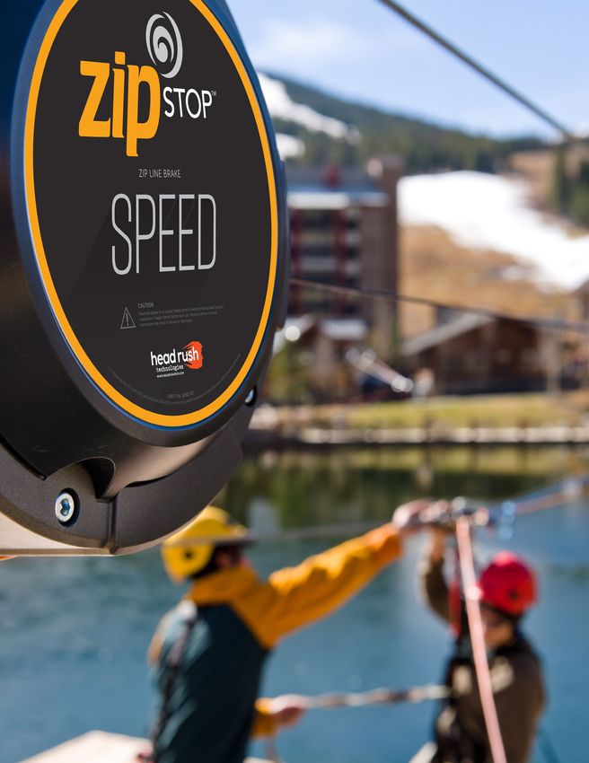
ZIPSTOP
ZIP LINE
BRAKE
Operation and Maintenance Manual
Models: ZS125-08 / ZSIR150-20A / ZSSD150-20A

NOTE TO OPERATORS
Always Read Instructions Before Use
The Operation and Maintenance manual contains information relating to the
proper operation, inspection and maintenance of the zipSTOP and includes all
product registration and warranty information. Participant safety is dependent on
actions of the operator(s). This document must be supplied to the owner after
installation. Ensure that this manual is readily available to the Responsible Parties
at all times.
Head Rush Technologies Manual - zipSTOP Operation and Maintenance Manual
P/N 13829-04
Head Rush Technologies products are covered by a number of patents, including
U.S. Patents 8,490,751; 8,851,235; 9,016,435; and D654,412 & corresponding patents/applications in the
USA and in other countries worldwide.
TABLE OF CONTENTS

SAFETY INFORMATION                                                4
   Safety Warnings                                                4
   Symbols Used in this Manual                                    6
   Safety Information                                             6
   Emergency Arrest Device (EAD) Confirmation                      7
   Regulations and Standards                                       7
   Warranty                                                        7
INTRODUCTION                                                      8
   How the zipSTOP Zip Line Brake Works                           8
   Models, Specifications, and Parts: zipSTOP and Brake Trolley   9
   zipSTOP Operation and Maintenance Manual                       11
ZIPSTOP OPERATION                                                 12
   Redirection/Reduction System Components                        12
   Operational Envelope                                           13
   Facility Operational and Training Procedure                    13
   Operating Procedure                                            13
INSPECTION AND MAINTENANCE                                        15
   Daily Inspection                                               15
   Weekly Inspection                                              16
   Bi-Annual Inspection                                           16
   Recertification                                                16
   Re-Commissioning Testing                                       17
   Webbing Inspection                                             17
   Webbing Replacement                                            21
   Nozzle Assembly Replacement                                    22
   Side Cover Replacement                                         23
   bumpSTOP Replacement                                           23
   Long Term Storage                                              24
IMPROPER OPERATION                                                25
MANUFACTURER’S DETAILS                                            26

www.headrushtech.com           |   +1-720-565-6885                 3
SAFETY INFORMATION

    Safety Warnings
    READ BEFORE INSTALLATION & OPERATION

                                                  WARNING

     DO NOT USE OR INSTALL A ZIPSTOP UNLESS AN EMERGENCY ARREST
     DEVICE (EAD) THAT PREVENTS SERIOUS INJURY* OR DEATH, MAKES
      THE BRAKING SYSTEM FAIL-SAFE, AND MEETS THE REQUIREMENTS
                  SPECIFIED IN THIS MANUAL IS PRESENT
     All Requirements and Instructions Must be Followed to Achieve Proper Operation and Participant Safety
           DO NOT USE A ZIPSTOP UNLESS ALL INSTRUCTIONS AND REQUIREMENTS ARE SATISFIED
       Prior to installation and operation, all Responsible Parties must have read and shown to have un-
       derstood all requirements, instructions, labels, markings and safety information pertaining to the
       correct installation, operations, inspection and maintenance of the zipSTOP brake, its component
       parts and all associated hardware and systems. Failure to do so may result in equipment damage,
       serious injury or death.

          *Serious injury includes any of the following injuries: fractures, amputations / dismember-
          ment, permanent loss of the use of a body organ / member / function / system, injury likely
          to lead to permanent loss or reduction of sight, any crush injury to the head or torso causing
          damage to the brain or internal organs, serious burns, any scalping, any loss of consciousness
          caused by head injury or asphyxia, significant disfigurement, loss of a fetus, or other signif-
          icant injury / illness that requires immediate admission and overnight hospitalization and
          observation by a licensed health care professional.
          Serious injury is also commonly determined by the Authority Having Jurisdiction, the more
          conservative definition applies.

                                                                        Definition from EN15567 and ASTM F2959

4                                                                www.headrushtech.com        |    +1-720-565-6885
WARNING
The following items are critical and must be understood by all persons involved with the installation, operation,
and service of a zip line utilizing a zipSTOP. This includes, but is not limited to: all Responsible Parties, guides /
operators, owners, service technicians, designers, installers, etc.
Emergency Arrest Device – a suitable Emergency Arrest Device (EAD) that meets the requirements
specified in this manual must be used at all times.
Arrival Speed – the device / configuration arrival speed limits must NEVER be exceeded.
Qualified Person(s) - The installation and commissioning of a zipSTOP equipped braking system must
be completed by a qualified person(s). Head Rush Technologies is not a zip line brake system designer or
installer and therefore cannot approve zip line braking systems.
Minimum Requirements – All minimum requirements in this manual must be satisfied
•• Redirection Rope – redirection systems require the use of Gorilla Rope or direct equivalent.
•• Compatible Components – all components used must be compatible with the system, including:
redirection pulley, brake trolley, rider trolley, etc.
Inspection – Prior to every descent, the redirection system and EAD must be inspected for readiness
including proper reset and entanglement hazards.
Correct Installation and Operation – This manual illustrates only some of the possible correct and
incorrect methods of installation and operation. It is impossible to address every scenario and configu-
ration relating to the use of this equipment. It is ultimately up to the qualified person(s) and Responsible
Party to ensure safe and correct installation and operation.
Risk Assessment and Rescue – A risk assessment including a ride and failure analysis must be conducted
and corresponding rescue plan in place prior to the installation and use of the zipSTOP.
www.headrushtech.com | +1-720-565-6885 5Symbols Used in this Manual
The following safety symbols are used throughout this manual to highlight potential danger to participants
and equipment. One or more precautions may be associated with practices and procedures described within
this manual. Failure to adhere to any precautions highlighted can result in equipment damage, serious injury or
death.
Indicates a potentially hazardous situation exists that, if warnings are not observed, may result
in improper operation, equipment damage, serious injury or death.
Indicates an action that must be taken to prevent improper operations, equipment damage,
serious injury or death.
Indicates a scenario, configuration, action, etc. that is not allowed and may result in improper
operation, equipment damage, serious injury or death.
Safety Information
The zipSTOP Brake assembly, including zipSTOP Brake Units Models zipSTOP ZS125-08, zipSTOP IR ZSIR150-
20A and zipSTOP SPEED ZSSD150-20A, zipSTOP Brake Trolley ZT125-17 and all accessories are designed and
specified for use in the recreational zip line industry as components within a braking system designed by a
qualified person. Use of the zipSTOP device or accessories for any purposes other than that intended by the
manufacturer is not permitted.
The zipSTOP is designed to be utilized as a Primary Brake or Emergency Arrest Device (EAD). When using the
zipSTOP as a primary brake, the Responsible Parties MUST utilize an independent EAD to protect against op-
erator error and equipment failure. When used as an EAD, the zipSTOP configuration must meet all Head Rush
Technologies’ and other applicable requirements. Design, installation, and qualification of the zip line ride,
including the braking system, must be completed by a qualified person and is the responsibility of the installer,
owner, engineer, designer or other Responsible Party.
Owners and Operators of zipSTOP devices are responsible for the safety and supervision of any person using
the zip line and are required to undergo training the the correct operation, inspection and maintenance prior
to any use. Designers, Installers and/or other Responsible Parties must assure that proper installation and op-
erational training are documented and provided to the Owner / Operator. Proper installation requires careful
design and planning using zipSTOP and non-zipSTOP components. Proper operational procedure is left up to
the Responsible Party and must ensure compatibility with all hardware, systems, other ride requirements and
procedures.
Responsible Parties are encouraged to seek the advice of a zip line installer, designer/engineer, or other quali-
fied person regarding the instructions in this Manual. Head Rush Technologies is not a designer or installer and
therefore cannot approve a zip line braking system.
THESE INSTRUCTIONS MUST BE MADE READILY AVAILABLE TO ALL RESPONSIBLE PARTIES
AT ALL TIMES.
6 www.headrushtech.com | +1-720-565-6885Emergency Arrest Device (EAD) Confirmation
THE EAD MUST PREVENT SERIOUS INJURY OR DEATH AND BE FAIL-SAFE. ZIP
LINES USING THE ZIPSTOP BRAKE ARE REQUIRED TO USE INDEPENDENT PRI-
MARY AND EMERGENCY ARREST DEVICES TO ARREST THE MOTION OF RIDERS.
Use of an EAD that prevents serious injury and makes the braking system fail-safe is required. The EAD must
automatically engage upon failure of the primary brake. An EAD cannot be dependent on a participant or
guide to engage upon failure of the primary brake and cannot be tethered to or use the reset of the zipSTOP
to reset the EAD.
Installation and use of a zipSTOP constitutes acknowledgement by the Responsible Party that the following
requirements regarding use of an adequate EAD have been satisfied:
The Installation and Operation and Maintenance Manuals have been understood by all Responsible Parties.
An adequate EAD rated to the arrival speed and weight range which makes the braking system fail-safe is
present, functional and inspected prior to every zip line descent.
The EAD has been tested by a qualified person in accordance with this manual, ASTM F2959 and other
requirements in accordance with the Authority Having Jurisdiction and has been shown to make the
braking system fail-safe independent of the primary brake for all rider weights, speeds and orientations.
Regulations and Standards
The zipSTOP, zipSTOP IR and zipSTOP SPEED devices and supplied components comply with all applicable
requirements of ASTM F2959-18 Standard Practice for Aerial Adventure Courses.
All zipSTOP Devices, Brake Trolley, and all Head Rush Technologies’ accessories are designed for use as
components within a zip line braking system. A zipSTOP device may be operated so long as a qualified person
designs and installs a suitable braking system that meets or exceeds all requirements stated in this manual and
any applicable requirements in accordance with the Authority Having Jurisdiction. Applicable standards may
include, but are not limited to, Association for Challenge Course Technology (ACCT), EN 15567-1 Sports and
Recreational Facilities – Ropes Courses, Professional Ropes Course Association (PRCA), ASTM F2959 Stan-
dard Practice for Aerial Adventure Courses, and ASTM F770 Standard Practice for Ownership and Operation of
Amusement Rides and Devices.
Warranty
Manufacturers sole warranty. The zipSTOP Brake assembly will be sold free from defects in materials and
workmanship, excluding field replaceable wear parts, for a period of one (1) year from date of purchase. This
warranty only applies to the original purchaser, and is contingent upon the Responsible Parties using and
maintaining the device in accordance with the zipSTOP instructions, including the requirement to maintain
annual recertification as described in the Installation and Operation and Maintenance Manuals.
This warranty is expressly in lieu of other warranties, express or implied, and any implied warranty of mer-
chantability or fitness for a particular purpose is hereby expressly excluded. The sole remedy for breach of said
warranty or for any claim in negligence or strict liability in tort is the repair or replacement of any defective
parts at the discretion of the manufacturer. Such parts claimed to be defective shall be returned to the Head
Rush Technologies Service Center, transportation prepaid, for inspection by an authorized Head Rush service
technician to determine to its satisfaction that said part(s) are defective.
This warranty is null and void if other than genuine parts are used, if any modifications are carried out to the
zipSTOP Brake assembly or zipSTOP components without the expressed written permission of the manufac-
turer, such as if used outside of intended application or beyond the stated device weight and speed limits.
No person, Agent or Distributor is authorized to give any warranty, other than the one herein expressed, on
behalf of the Company or to assume for it any liability pertaining to such products. The company makes no
warranties in respect to trade accessories or component parts which are not manufactured by the company,
same being subject only to such warranties, if any, as may be made by their respective manufacturers.
www.headrushtech.com | +1-720-565-6885 7INTRODUCTION
How the zipSTOP Zip Line Brake Works
The zipSTOP Zip Line Brake is a patented self-regulating eddy current braking device designed to be used as a
component within the braking system at the terminal end of a zip line. The zipSTOP has a self-regulating brake
design and can accommodate a range of rider weights and arrival speeds without external input. The zipSTOP
is connected to a brake trolley at the terminal end of the zip line; when the arriving rider contacts the brake
trolley the webbing is pulled out from the zipSTOP which transmits braking force to the rider. The extension of
the webbing spins a conductive rotor within a counter-rotating magnetic field. The relative motion between
the rotor and magnetic field creates a magnetic drag force, called eddy current braking (ECB), due to elec-
tromagnetic induction, providing a braking force to the webbing and brake trolley gently stopping the rider.
After the rider dismounts, a spring within the zipSTOP automatically retracts the webbing and resets the brake
trolley so it is ready for the next rider.
Every zip line is different and every braking system must be designed to satisfy specific requirements. Three
different zipSTOP models are available which may be configured in different ways to accommodate a range of
arrival speeds, weights and site specific conditions. The Responsible Parties must ensure the finalized brak-
ing system is satisfactory for the allowable operational range, meets the needs of the system and applicable
standards. Unmanned testing and qualification is required with all installations. The intention of this manual is
to provide guidance on standard practices and common configurations; it is not intended to address every
possible configuration or scenario. It is ultimately up to the Responsible Parties to ensure the complete braking
system is adequate and compatible with the requirements and needs of the zip line.
Additional information regarding the installation and use of zipSTOPs, EADs, accessories, inspection, mainte-
nance and many other topics may be found at www.headrushtech.com.
THE FIGURES PRESENTED IN THIS MANUAL ARE NOT TO SCALE AND MAY NOT SHOW ALL
REQUIRED COMPONENTS OR STRUCTURES, INCLUDING, BUT NOT LIMITED TO: EAD,
ANCHORS, GUY LINES, SAFETY EQUIPMENT, ETC.
IT IS UP TO THE RESPONSIBLE PARTY TO ENSURE THAT THE BRAKING SYSTEM INCLUDES
ALL NECESSARY EQUIPMENT, IS APPROPRIATELY DESIGNED AND FUNCTIONAL FOR THE
LIFE OF THE ZIPLINE. THIS MAY INCLUDE PERIODIC INSPECTION, MAINTENANCE AND
REPLACEMENT OF COMPONENTS.
THIS MANUAL IS FOR OPERATION AND MAINTENACE ONLY. ZIPSTOP DEVICES MUST BE
INSTALLED BY A QUALIFIED PERSON.
8 www.headrushtech.com | +1-720-565-6885Models, Specifications, and Parts: zipSTOP and Brake Trolley
Three models of zipSTOP are available to accommodate a range of arrival speeds. Every zipSTOP comes with
a brake trolley and mounting bracket for anchoring the zipSTOP. The owner should keep the original packag-
ing to use for storage and shipping of the device.
All zipSTOP Models
OPERATING TEMPERATURE -4°C (25°F) to 60°C (140°F)
OPERATING TEMPERATURE DRY -10°C (14°F) to 60°C (140°F)
STORAGE TEMPERATURE -20°C (-4°F) to 60°C (140°F)
WEIGHT RANGE 15 to 150 kg (33 – 330 lbs)
zipSTOP Brake Unit, ZS125-08
MAXIMUM WEBBING EXTENSION 12.5 m (41 ft)
MAXIMUM ARRIVAL SPEED 1:1 Redirection Ratio 36 km/h (22 mph)
2:1 Redirection Ratio 60 km/h (37 mph)
zipSTOP IR Brake Unit, ZSIR150-20A
MAXIMUM WEBBING EXTENSION 20 m (65 ft)
MAXIMUM ARRIVAL SPEED* 1:1 Redirection Ratio 60 km/h (37 mph)
* Only 1:1 Redirection Ratio Allowed
zipSTOP SPEED Brake Unit, ZSSD150-20A
MAXIMUM WEBBING EXTENSION 20 m (65 ft)
MAXIMUM ARRIVAL SPEED** 2:1 Redirection Ratio 72 km/h (45 mph)
** Only 2:1 Reduction Ratio Allowed
NOTE: All Reduction Ratios must be configured properly for reliable, automatic reset. Operating without reliable,
automatic reset is not allowed.
NOTE: Maximum webbing extension is not the braking distance, but refers to the amount of webbing in the device.
Refer to the braking distance charts to see Braking Line Extension.
zipSTOP Brake Trolley
ZT 125-17-1/2 For use with ½ inch [12-13mm] zip lines
ZT 125-17-5/8 For use with 5/8 inch [16mm] zip lines
ZT 125-17-3/4 For use with 3/4 inch [19mm] zip lines
www.headrushtech.com | +1-720-565-6885 9The following nomenclature and components are referenced throughout the Installation and Operation and
Maintenance Manuals.
zipSTOP Mounting Base Mounting Pin / Lynch Pin
Nozzle Assembly
Webbing Assembly
rattleSTOP
Side Cover
Serial Number Label
Recertification Label
zipSTOP Information Label
Certification Label
zipSTOP Specification Label
Model Label Specification Label
10 www.headrushtech.com | +1-720-565-6885zipSTOP Operation and Maintenance Manual
This Operation and Maintenance Manual includes instructions for all Responsible Parties who will be operating
the zipSTOP or otherwise assisting a rider’s zip line ride which uses a zipSTOP. This is predominately facility
“guides” but also owners, service technicians, builders/installers conducting tests, inspectors, etc. A separate
zipSTOP Installation Manual (PN 11911) is also supplied with each device and addresses the installation, testing,
commissioning, etc. associated with using a zipSTOP within a braking system. The Installation Manual provides
further understanding of how a zipSTOP operates, what associated components may be required and what
factors influence performance.
This manual addresses the basic principles of zipSTOP operation but does not cover site specific operational
procedures including, but not limited to: participant anchoring, safety at height, connection to and dismount
from the zip line, additional equipment such as rider trolleys, harnesses, helmets, or emergency and site res-
cue plans. This manual addresses proper operation, inspection, and maintenance of the zipSTOP device only.
ADDITIONAL PROCEDURES ARE REQUIRED FOR PARTICIPANT SAFETY AND PROPER
OPERATION OF THE ZIP LINE AND BRAKING SYSTEM. THE INSTRUCTIONS IN THE
MANUAL ADDRESS ZIPSTOP OPERATION ONLY.
www.headrushtech.com | +1-720-565-6885 11ZIPSTOP OPERATION
Redirection/Reduction System Components
The below diagrams illustrate the typical components within a typical zipSTOP line braking system. Depending
on the installation, additional or fewer components may be required.
Traveler Assembly Overhead Line Fixed Support Pulley(s)
Redirection Point/
Webbing Assembly Redirection Rope Secondary Anchor
zipSTOP Primary
Anchor Point
Emergency Arrest Device zip Line
Brake Trolley
EAD
Redirection System Components
Maximum Webbing Extension
Webbing
Extension Pivot Height
(1m Minimum)
Buffer
Zone
EAD
Braking Zone
Minimum
Braking Zone Reset Point
Maximum
Landing Area
Braking Zone Dimensions
12 www.headrushtech.com | +1-720-565-6885Operational Envelope
Prior to operation, every zipSTOP braking system must be tested and an operational envelope established by
the Responsible Party in accordance with the zipSTOP Installation Manual. The operating envelope is the set of
limits and conditions which zip line operations must stay within to ensure proper operation of the zip line and
braking systems, particularly arrival speed.
THE DOCUMENTED OPERATING PROCEDURE MUST INCLUDE PROVISIONS AND PROCE-
DURES TO PREVENT OPERATION OUTSIDE THE OPERATIONAL ENVELOPE, ACCOUNTING
FOR: WIND SPEED / DIRECTION, WEIGHT, RIDER POSITION, ETC.
THE MAXIMUM ARRIVAL SPEED MUST NEVER BE EXCEEDED FOR THE PRIMARY BRAKING
SYSTEM AND EAD IN ANY CONDITION.
Facility Operational and Training Procedure
Facilities utilizing a zipSTOP must have and follow a documented operational and training procedure which
addresses all necessary tasks for proper operation, maintenance, inspection, safety, rescue etc. This document
must take into account all items within this manual as well as any item pertaining to site specific requirements,
safety and rescue. Association for Challenge Course Technology (ACCT) guidelines, Professional Ropes Course
Association (PRCA) guidelines or ASTM F770: Standard Practice for Ownership, Operation, Maintenance, and
Inspection of Amusement Rides and Devices, etc. may be utilized as a reference. It is up to the Responsible
Parties to generate this procedure, perform training, and ensure efficacy and adherence.
Operating Procedure
PRIOR TO DAILY OPERATIONS, THE ZIPSTOP DEVICE AND ASSOCIATED COMPONENTS MUST
BE INSPECTED AND DOCUMENTED IN ACCORDANCE WITH SECTION: DAILY INSPECTION.
THE FOLLOWING INSPECTION AND OPERATIONAL PROCEDURE FOR OPERATION
OF A ZIPSTOP ONLY. THE ZIP LINE OPERATIONAL AND TRAINING PROCEDURE
MUST INCLUDE THESE ITEMS IN ADDITION TO ALL OTHER SAFETY AND SITE SPE-
CIFIC REQUIREMENTS.
1. Inspect proper reset and braking system readiness
a. EAD is ready, operational and correctly located.
b. There are no participants or obstacles on the zip line which may interfere with an arriving rider or
any part of the braking system.
c. Webbing is properly retracted into the zipSTOP.
d. Brake trolley is in the reset positon and correctly oriented.
e. The redirection system / components are not twisted, entangled, and are running free and clear.
f. Operational / environmental conditions, particularly wind direction and speed, are within the opera-
tional envelope.
2. Rider Attachment and Descent
a. Prior to rider descent, procedures must be in place to ensure system readiness, correct operation-
al procedures are followed and communicate zip line status between the launch and arrival areas.
This may include guide verbal or visual communication, safety related control systems (SRCS), etc.
www.headrushtech.com | +1-720-565-6885 13b. Riders must descend one at a time.
3. Rider Braking
a. zipSTOP braking mechanism engages and self-regulates without external input from rider or guide.
b. Avoid contact and pinch hazard between the rider and moving objects including rider trolley, brake
trolley, redirection system and/or other components. Rider swing up during braking must be ac-
commodated.
4. Rider Recovery / Dismount
a. After rider has reached a full stop, guide may facilitate rider recovery and dismount.
5. System reset
a. After rider dismount, brake trolley and braking system shall be allowed to reset automatically.
OPERATORS MUST BE AWARE OF AND TAKE THE FOLLOW PRECAUTIONS AT
ALL TIMES IN ADDITION TO THE OPERATING PROCEDURE.
ALL DEFICIENCIES MUST BE CORRECTED PRIOR TO RIDER DESCENT.
Ensure reliable reset after every descent
•• The braking system must be designed such that reliabe reset is achieved after every use. Operation
without reliable reset is not allowed. Failure of the zipSTOP to reset the brake trolley will result in no
braking from the zipSTOP, inadequate braking, abrupt braking, etc.
Redirection ropes can become twisted, entangled or rub on an overhead cable, the main zip line cable,
other structures or components.
•• Damage to redirection ropes, webbing or other textiles will occur if it contacts other components
under load or motion. Inspection for damage MUST occur at least daily and as required.
•• Ropes becoming entangled with a participant present a dangerous scenario; provisions must be pres-
ent to prevent rider entanglement.
•• Separation of the redirection rope or zipSTOP webbing will disconnect the rider from the braking sys-
tem resulting in no braking from the zipSTOP. An adequate EAD must be capable of arresting a rider
in all conditions in this event.
Avoid rider contact with any zip line or braking components.
•• Serious injury may result if the rider contacts the trolley or other components when it impacts the
brake trolley. Design or operational procedures must be in place to prevent the rider from contacting
or having any part of their body caught between the rider trolley and brake trolley.
•• Non-forward facing arrival may result in riders’ heads being in closer proximity to the zip line. Serious
injury due to upswing may result if rider is not in the forward-facing position. When the possibility
of non-forward-facing arrival exists, ensure riders cannot come into contact with the zip line, brake
trolley or other objects during deceleration.
Never exceed device weight or speed limits.
•• Exceeding device limits may cause improper operation, webbing damage, and/or internal device
damage which cannot be visually inspected. If this occurs the zipSTOP will need to be sent to an Au-
thorized Service Agent for inspection and repair.
14 www.headrushtech.com | +1-720-565-6885INSPECTION AND MAINTENANCE
ALL ZIPSTOP DEVICES MUST BE INSPECTED AND MAINTAINED IN ACCORDANCE WITH
THIS MANUAL. RECORDS OF INSPECTION, SERVICE, COMPONENT REPLACEMENT AND
OTHER MAINTENANCE MUST BE KEPT.
Always use genuine Head Rush replacement parts; any modifications without the expressed written consent
of Head Rush Technologies is not allowed. Third party components shall be inspected and serviced in accor-
dance with that manufacturer’s instructions. Supplemental instructions, demonstration videos and inspection
logs are available at headrushtech.com.
Daily Inspection
Prior to daily operations, the zipSTOP device and associated components must be inspected. Inspection of
the zipSTOP includes, at minimum, the below items. Additional structures, systems and equipment shall be
inspected in accordance with the facility’s documented procedure, manufacturers’ instructions and/or other
instructions from the Responsible Party.
1. Device Condition – Visually inspect the exterior of the zipSTOP device for damage, corrosion, loose
fittings and fasteners.
2. Device Mount – Inspect the zipSTOP Brake Unit mounting bracket and pins for damage and ensure
device and mount are suitably secured.
3. Webbing Assembly – Fully extend the Braking Line from the zipSTOP Brake Unit. Check the line con-
dition for damage or discoloration, refer to Section: Webbing Inspection. If worn or damaged, replace
with a new webbing assembly.
4. Webbing Extension and Retraction – Check that the webbing extension and retraction is smooth,
maintains resistance throughout its range and the webbing is properly retracted.
5. Brake Trolley Bumper – Check that the Brake Trolley bumpSTOPs are secure and free from damage or
excessive wear that will hinder performance.
6. Brake Trolley Operation – Check the Brake Trolley is free from damage and operates smoothly
throughout its operating range and that it correctly resets to the reset point.
7. Redirection Rope and Pulleys – Inspect the redirection rope and pulleys to ensure the rope runs free
and clear without entanglement or abrasion. Inspect overall condition of entire line, terminations and
ensure it is in operable condition. Replace if necessary.
8. Connecting Hardware – Check that all connecting and additional hardware is in operational condition,
secure and free of corrosion.
9. Traveler Assembly – Inspect that all hardware is secure and free from damage. Check that the assembly
runs free and clear.
10. EAD – Inspect EAD condition and operation per manufacturer’s instructions.
www.headrushtech.com | +1-720-565-6885 15Weekly Inspection
Once weekly, the condition of the device casing and side covers shall be visually inspected for damage or
corrosion. If operating in a salty or harsh environment, remove the side covers and visually inspect the inter-
nal components for corrosion. If red rust is found, the device must be immediately taken out of service and
returned for recertification. White scaling is acceptable and does not require a recertification. Reinstall the side
covers after inspection.
Bi-Annual Inspection
Once every 6 months, the condition of the internal drum lead, shackle/shackle pin and nozzle assembly shall
be visually inspected for wear and damage. Inspect the drum lead and webbing assembly termination for dam-
age, refer to Section: Webbing Inspection. Inspect the shackle and shackle pin for damage or deformation.
Unless replacing the webbing, do not loosen or tighten the shackle pin as this will break the thread locking
compound. Inspect the nozzle assembly for damage and wear of the stainless steel insert.
Recertification
The zipSTOP Brake Unit requires an annual service and recertification to be carried out by an Authorized
Headrush Service Agent. The zipSTOP should be packaged in its original protective foam and box in order to
safeguard the device from damage during shipping.
The recertification expiration date is shown on the recertification label located on the device casing. Dismount
the zipSTOP device and return to an Authorized Service Center prior to the Next Recertification Date shown.
To dismount, follow instructions provided in the zipSTOP Installation Manual and/or instructions provided by
the Responsible Party. Document the orientation and connection details prior to dismounting device to aid
reinstallation.
SERIAL NUMBER:
MANUFACTURE
DATE:
RECERTIFICATION
DATE:
NEXT RECERT
REQUIRED:
BY:
10024-01
“Next Recert Required” Date Shown Here
DO NOT OPERATE AFTER THE NEXT RECERTIFICATION DATE ON THE RECERTIFICATION LABEL.
16 www.headrushtech.com | +1-720-565-6885Re-Commissioning Testing
Because many elements can change over time, it is a requirement that periodic testing be performed of the
zip lines and braking system to verify original performance. Testing shall be conducted anually and upon any
modification that may affect zip line or braking system performance. Periodic load testing and monitoring is
the only way to ensure that arrival speeds remain as designed and stay within established limits. Refer to the
zipSTOP Installation Manual and/or documents from the Responsible Parties for additional information, proce-
dures, and requirements.
RE-COMMISSIONING TESTING IS REQUIRED ANNUALLY AND UPON ANY MODIFICATIONS THAT MAY
AFFECT ZIP LINE OR BRAKING SYSTEM PERFORMANCE. CONSULT WITH YOUR BUILDER AND THE
INSTALLATION GUIDE PROVIDED WITH THE ZIPSTOP. REPLACEMENT MANUALS CAN BE DOWN-
LOADED FROM HEADRUSHTECHNOLOGIES.COM
Webbing Inspection
INSPECT THE WEBBING ASSEMBLY DAILY IN ACCORDANCE WITH THE FOLLOW-
ING INSTRUCTIONS. USING THE DEVICE WITH UNACCEPTABLE WEAR OR DAMAGE IS
PROHIBITED.
The webbing assembly is a wear component which requires daily inspection and periodic replacement when it
shows signs of wear, damage or contamination. More frequent inspection may be required for high through-
put facilities or when operating in harsh environments. Refer to Wear Tables, below, for examples of accept-
able and unacceptable wear. These tables do not include all possible types of wear or damage, if in doubt
remove webbing from service. Webbing must be removed from service if it does not pass inspection. Refer to
the Webbing Wear Troubleshooting Chart for possible causes of accelerated webbing wear. Continued use of
webbing beyond stated limits may result in separation, disconnecting the rider from the braking system.
To inspect the webbing, extract the entire length from the device and carefully examine both edges and faces
for wear or damage including:
Damage to stitching
Cuts to the face or edges
UV degradation including discoloration, fading, brittleness or chalking
Hard fibers
Surface glazing or melting appearance
Permanent deformation or warping
Contamination from chemicals, dirt, grit, sand, dust, etc.
www.headrushtech.com | +1-720-565-6885 17WEAR TABLES
Webbing pictures outlined in red in the tables below show webbing that MUST be taken out of service and replaced immedi-
ately to continue using your zipSTOP. The green outlined photos show webbing that can be kept in operation.
zipSTOP
Degree of Wear Side Wear Face Wear
NEW
STAGE 1
STAGE 2
STAGE 3
STAGE 4
zipSTOP Webbing Wear Table
18 www.headrushtech.com | +1-720-565-6885WEAR TABLES
Webbing pictures outlined in red in the tables below show webbing that MUST be taken out of service and replaced immedi-
ately to continue using your zipSTOP. The green outlined photos show webbing that can be kept in operation.
zipSTOP IR/ zipSTOP SPEED
Degree of Wear Side Wear Face Wear
NEW
STAGE 1
STAGE 2
STAGE 3
STAGE 4
STAGE 5
zipSTOP IR / zipSTOP SPEED Webbing Wear Table
www.headrushtech.com | +1-720-565-6885 19Symptom Potential Cause Potential Solution
Replace with genuine Head Rush
Normal wear and tear
Technologies webbing assembly
Ensure zipSTOP is mounted cor-
rectly and the webbing is coming
Webbing not extracted straight
straight out of the nozzle. Refer
from nozzle
to Installation Manual for correct
configuration.
Webbing face or side wear
Check that the webbing is running
Webbing is rubbing on obstruc-
free and clear of all structures,
tion.
objects, etc.
Inspect nozzle and stainless steel
insert for wear, burrs or other
Nozzle is damaged.
damage. Nozzle is a wear item,
replace if necessary.
Foreign objects including dirt, Cover the zipSTOP when not in
sand, debris, etc. have contami- use. Wipe webbing clean with a
nated webbing and/or device. dry cloth daily.
Adjust redirection rope so web-
Bar tack damage Fast retraction, impact with nozzle
bing does not run into nozzle.
Cease operations immediately.
Device has experienced over-
Sudden webbing wear, particularly Unit will require internal inspec-
speed (arrival faster than device/
side separation/stringing tion and service by Authorized
configuration maximum).
Service Agent.
Whenever the zipSTOP will not
be used or will be stored for an
extended period after use in wet
Webbing stored or not being dried
Webbing shows mold, mildew conditions, fully extend webbing
after use in wet conditions
and allow to dry in clean, dry en-
vironment out of the sun. Do NOT
use heat to dry webbing.
Ensure webbing is fully retracted
Webbing has been subjected to
Webbing is faded or discolored into device when not in use, avoid
high UV exposure or chemicals.
chemical exposure.
Webbing Wear Troubleshooting Chart
20 www.headrushtech.com | +1-720-565-6885Webbing Replacement
Replacement of the webbing assembly may be carried out with the zipSTOP in place or removed and secured
to a workbench.
To replace the webbing assembly:
1. Disconnect the redirection system from the end of the zipSTOP webbing
2. Remove the nozzle assembly
3. Extract the entire length of webbing including the drum lead
4. Use a suitable holding pin through the loop in the drum lead above the shackle, Figure 6. This will pre-
vent the line from retracting back into the device.
IF THE DRUM LEAD RETRACTS BACK INTO THE DEVICE THE DEVICE WILL REQUIRE SER-
VICE BY AN AUTHORIZED SERVICE AGENT, DO NOT USE.
5. Unscrew the shackle pin and remove webbing assembly. Discard the old shackle pin. Cut off ends of
used webbing before discarding to ensure it is not accidently re-used.
ALWAYS USE A NEW SHACKLE PIN PROVIDED WITH THE WEBBING REPLACEMENT. NEW
SHACKLE PINS COME WITH SINGLE USE ONLY THREAD LOCKING COMPOUND.
6. Install the new webbing assembly and shackle pin ensuring the shackle loop is fitted to the drum lead
and shackle pin to the end of the webbing. Ensure that the new webbing assembly is correct for the
device model.
7. Tighten the shackle pin until fully seated
8. Remove the holding pin and allow the line to slowly retract without twisting until the drum lead and
sewn webbing end are inside the device
9. Replace the nozzle assembly
10. Allow the webbing to slowly retract into the device without twisting while maintaining constant tension.
Ensure the retraction force is smooth and adequate resistance is felt.
11. Once the line is fully retracted, pull the line out a short distance (~1m) and allow it to retract. Repeat
two or three times to ensure the line is firmly wound onto the drum.
12. If necessary, reinstall the zipSTOP and reconnect the redirection system.
www.headrushtech.com | +1-720-565-6885 21Drum Lead
Holding Pin
Shackle
Shackle Pin
Shackle
Shackle Pin
Webbing Assembly Drum Lead Webbing Assembly
Webbing - Drum Lead Connection
Nozzle Assembly Replacement
The nozzle assembly is located on the zipSTOP Brake Unit casing and provides guidance for the webbing
during extraction/retraction. The nozzle assembly is a wear component and will need to be inspected regular-
ly; replacement is on a conditional basis. Service of the nozzle assembly may be carried out with the zipSTOP
in place or removed and secured to a workbench.
To remove the nozzle assembly:
1. Secure or hold the webbing to prevent it retracting into the device when the nozzle is removed.
2. Extract the U-shaped nozzle pin using a flat head screwdriver or comparable tool
3. Remove the two nozzle halves
Nozzle Pin
2
Stainless Steel
Nozzle Insert
NOTE: Webbing Nozzle Housing
not shown
3
Nozzle Assembly
To re-install the nozzle assembly, reverse the above steps.
DO NOT OPERATE THE ZIPSTOP WITHOUT THE NOZZLE ASSEMBLY PROPERLY INSTALLED.
22 www.headrushtech.com | +1-720-565-6885Side Cover Replacement
The zipSTOP Brake Unit side covers are removable and simply snap into place on the device casing. Remove
side covers by placing a flat head screwdriver under the edge of the cover and carefully levering it up. To re-
place, align the outer profile of the side cover with the profile of the casing and snap into place.
DO NOT OPERATE THE ZIPSTOP WITH SIDE COVERS REMOVED.
Side Cover
Side Cover Assembly
bumpSTOP Replacement
The bumpSTOP is a rubber bumper attached to the front of the brake trolley and requires periodic replace-
ment when worn.
To replace the bumpSTOPs:
1. Remove the four (4) screws connecting the bumpSTOP and backing plate to the brake trolley.
2. One at a time, align the bumpSTOPs with the mating holes of the brake trolley and reinstall hardware.
3. Tighten bolts to 2.5 Nm [1.8 ft-lbs].
www.headrushtech.com | +1-720-565-6885 234 x 2.5Nm [1.8 ft-lbs]
bumpSTOP Assembly
DAMAGE TO BUMPSTOPS CAN RESULT IN IMPROPER BRAKING AND DAMAGE TO RIDER
TROLLEYS. REPLACE BUMPSTOPS WHEN WORN.
Long Term Storage
If the zipSTOP Brake Unit is to be placed into storage or left unused for longer than two weeks, ensure the unit
is clean and dry and protected from the environment. Ensure the webbing assembly is fully retracted into the
unit. Always store in a clean, cool and dry environment, preferably in the original packaging. Upon reinstalla-
tion of the device, carry out unmanned testing to recommission.
After exposure to water or damp conditions, thoroughly clean and dry the zipSTOP prior to storage. Ensure
that the zipSTOP is not left with a wet webbing retracted inside the casing as this may result in corrosion of the
unit and deterioration of the webbing. To dry the webbing / device, remove the side covers and fully extend
the wet webbing assembly and allow to completely dry in a clean environment prior to storing the device.
Ensure that debris does not enter the unit when side covers are removed. Reinstall the side covers prior to
storing or using the unit.
DO NOT STORE THE ZIPSTOP, WEBBING ASSEMBLY OR ASSOCIATED COMPONENTS IN A WET CON-
DITION. STORAGE MUST BE IN A CLEAN, COOL, AND DRY ENVIRONMENT IN ACCORDANCE WITH
THESE INSTRUCTIONS.
NEVER USE HEAT TO DRY THE WEBBING OR DEVICE.
24 www.headrushtech.com | +1-720-565-6885IMPROPER OPERATION
THE FOLLOWING SCENARIOS ARE NOT ALLOWABLE, MAY CAUSE
DEVICE DAMAGE, AND CREATE A DANGEROUS SCENARIO WHICH
COULD RESULT IN EQUIPMENT DAMAGE, SERIOUS INJURY OR DEATH.
Arriving faster than the device maximum may cause the following:
•• Separation or damage of the webbing and/or redirection rope.
•• Internal device damage to the zipSTOP which is not inspectable. This damage will cause sudden and
repeated webbing damage during normal operation. If this occurs, the zipSTOP will need to be sent
to an Authorized Servicing Agent for inspection and repair.
•• Exceeding the maximum braking distance resulting in undesired contact with the EAD.
•• Overextension of the webbing causing an abrupt stop and damage to the webbing/device.
•• Excessive braking force and rider swing up.
Arriving with a higher weight than the device maximum may cause the following:
•• Separation or damage of the webbing and/or redirection rope.
•• Internal damage to the zipSTOP which is not inspectable. This damage may and manifest as problems
with webbing retraction, extension.
Using multiple zipSTOP devices simultaneously (in parallel) may cause the following:
•• Abrupt braking and rider swing up.
•• Damage to the webbing, redirection rope and/or zipSTOP internal components.
Braking more than one rider at a time may cause the following:
•• Separation or damage of the webbing and/or redirection rope.
•• Abrupt braking and rider swing up.
•• Damage to the internal retraction spring resulting in failure to retract / reset.
•• Internal damage to the zipSTOP which is not inspectable.
www.headrushtech.com | +1-720-565-6885 25MANUFACTURER’S DETAILS
ADDRESS CONTACT DETAILS
Head Rush Technologies +1-720-565-6885
1699 Cherry Street, Suite C www.headrushtech.com
Louisville, CO 80027 USA info@headrushtech.com
26 www.headrushtech.com | +1-720-565-6885www.headrushtech.com | +1-720-565-6885 27
REGISTER YOUR DEVICE
     Get automatic updates on recertification and product information – visit headrushtech.com/register

                           ANNUAL RECERTIFICATION IS REQUIRED
           Please keep the shipping box for your device. For instructions on annual recertification,
                                  visit headrushtech.com/annual-service

+1-720-565-6885                        www.headrushtech.com                             info@headrushtech.com
                                                                                                       Apr 2021
You can also read