WIRELESS SECURITY CAMERA SYSTEMS - USER'S MANUAL
←
→
Page content transcription
If your browser does not render page correctly, please read the page content below
www.xmarto.com

               USER’S MANUAL

WIRELESS SECURITY CAMERA SYSTEMS

               1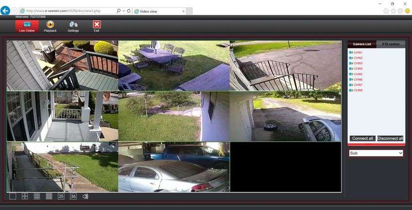
www.xmarto.com

Preface
Thank you for choosing xmartO products! By purchasing a Night Owl product, you receive a one (1)
year warranty covering manufacturing defects in material and workmanship.

This user manual is to introduce the operations of xmartO wireless camera systems in more details. If
there is any other question which is not covered in this user manual, please contact xmartO support at
support@xmarto.com.

Statement
   ·Though we apply all efforts to make the manual complete and accurate, there could still be some
discrepancies due to products’ timely update.
   ·The products and manual are subject to change without previous notification.
   ·The content in this manual is only for users’ reference. We don’t promise it’s exactly the same
 with the products you purchase. Detailed information is in accordance with the final products.
   ·The accessories and parts mentioned in this manual are only for product using guide purpose and
 not necessarily to be included in your purchased item.

Special Statement
Please comply with local laws and regulations when you use the surveillance devices.

About default settings

  ·The default username for NVR is admin (admin is the super administrator ID)
  ·The default password for account admin is empty, means no password.
  ·The default IPv4 address of NVR is: 192.168.1.114
  ·The default setting of NVR is to overwrite oldest recorded videos when hard drive is
  full.
  ·The device will start Setup Wizard by default when NVR is powered on.
  ·The default NVR resolution is 1280 x 1024.

                                                   1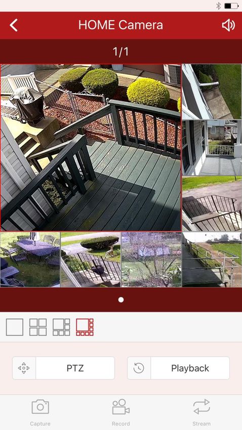
www.xmarto.com

       Contents

Preface ............................................................................................................................................................................ 2
2. Product Overview ....................................................................................................................................................... 6
     2.1 Introduction ...................................................................................................................................................... 6
     2.3 Specifications ................................................................................................................................................... 7
     2.4 Product Key Features........................................................................................................................................ 8
3. Operation Instructions ................................................................................................................................................ 9
     3.1 NVR Diagram................................................................................................................................................... 9
     3.2 Camera Diagram............................................................................................................................................. 10
     3.3 Mouse Operation ............................................................................................................................................ 11
     3.4 Input Method .................................................................................................................................................. 11
     3.5 Frequently Used Buttons ................................................................................................................................ 12
4. Installation & Connection......................................................................................................................................... 13
     4.1 Installation Precautions................................................................................................................................... 13
     4.4 Install Hard Drive ........................................................................................................................................... 15
     4.5 Camera Mounting Spots ................................................................................................................................. 17
     4.6 Antenna Mounting Tips .................................................................................................................................. 18
5. Getting Started ...................................................................................................................................................... 19
     5.3 Startup/ Login/ Logout/ Reboot/ Close screen display/ Shutdown ................................................................. 22
           5.3.1 Startup.................................................................................................................................................. 22
           5.3.2 Logout.................................................................................................................................................. 23
           5.3.3 Reboot.................................................................................................................................................. 24
           5.3.4 Close screen display ............................................................................................................................ 24
           5.3.5 Shutdown ............................................................................................................................................. 24
     5.4 Device Manage ............................................................................................................................................... 24
           5.4.1 Add Device. ......................................................................................................................................... 27
           5.4.2 Modify Device ..................................................................................................................................... 28
           5.4.3 Advanced ............................................................................................................................................. 30
           5.4.4 Delete Device ...................................................................................................................................... 31
           5.4.5 Manual Edit ......................................................................................................................................... 31
           5.4.6 Repeater ............................................................................................................................................... 32
     5.5 Channel Setting (CH Setting) ......................................................................................................................... 34
           5.5.1 Encode Setting ..................................................................................................................................... 33
           5.5.2 Channel OSD ....................................................................................................................................... 34
           5.5.3 Bitrate .................................................................................................................................................. 34
           5.5.4 Channel Details.................................................................................................................................... 35
           5.5.5 IP Camera ............................................................................................................................................ 36
    5.6 Network Setting ................................................................................................................................................ 37
           5.6.1 Network Setting ................................................................................................................................... 37
           5.6.2 DDNS .................................................................................................................................................. 38

                                                                                          2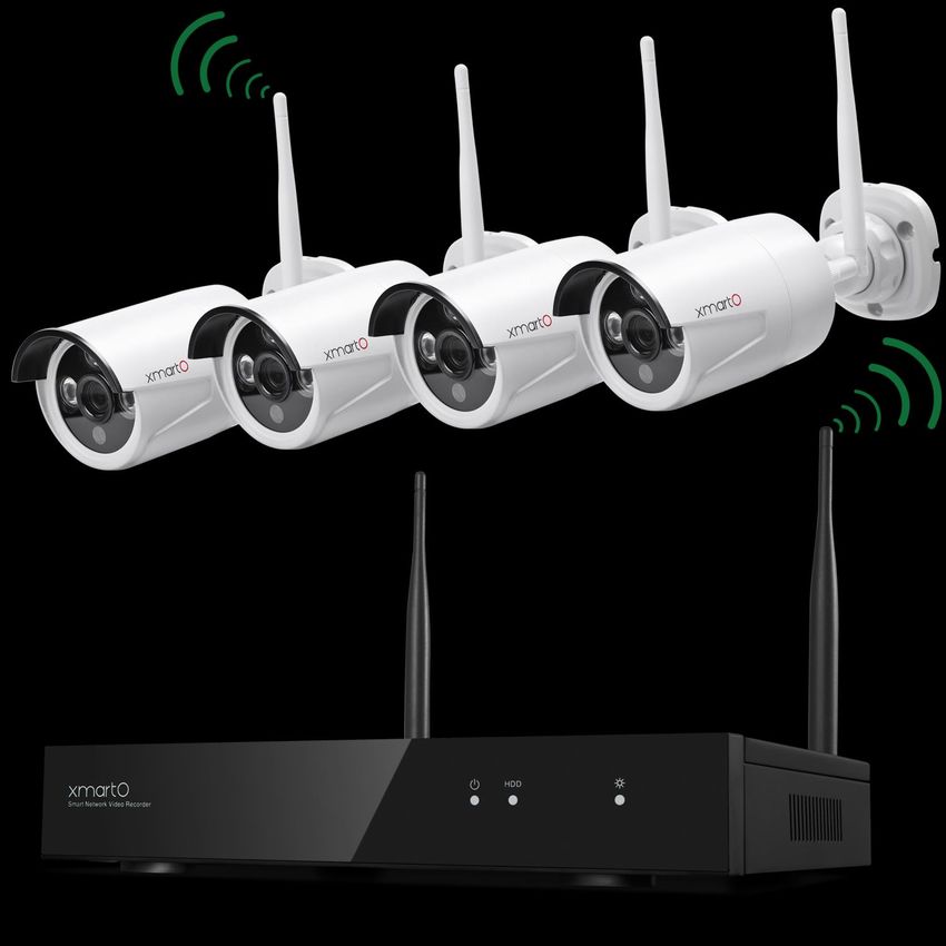
www.xmarto.com
5.6.3 E-Mail .................................................................................................................................................. 40
5.6.4 PPPoE .................................................................................................................................................. 41
5.6.5 3G ........................................................................................................................................................ 42
5.6.6 WiFi Setting ......................................................................................................................................... 42
5.6.7 PTZ Setting .......................................................................................................................................... 43
5.6.7.1 PTZ Parameter Setting...................................................................................................................... 43
5.6.7.2 PTZ Control Operations ................................................................................................................... 44
5.6.7.3 PTZ Auto Cruise Setup ..................................................................................................................... 45
5.7 Record Setting ................................................................................................................................................ 45
5.7.1 Manual Record .................................................................................................................................... 45
5.7.2 Time-scheduled Recording. ................................................................................................................. 46
5.7.3 Motion Detection Recording ............................................................................................................... 47
5.7.4 Alarm-triggered Recording (Sensor Recording) .................................................................................. 50
5.8 Video Playback ............................................................................................................................................... 51
5.8.1 Fast Playback ....................................................................................................................................... 51
5.8.2 Manual Playback ................................................................................................................................. 52
5.9 Video Backup ................................................................................................................................................. 52
5.10 Alarm ............................................................................................................................................................ 53
5.10.1 Motion Detection Alarm .................................................................................................................... 53
5.10.2 Video Loss Alarm .............................................................................................................................. 54
5.11 General setting .............................................................................................................................................. 55
5.11.1 General setting ................................................................................................................................... 55
5.11.2 Time Setting ....................................................................................................................................... 56
5.11.3 Screen setting ..................................................................................................................................... 57
5.11.4 HDD Setting ...................................................................................................................................... 58
5.12 System Admin .............................................................................................................................................. 60
5.12.1 System Version .................................................................................................................................. 60
5.12.2 HDD Info. .......................................................................................................................................... 61
5.12.3 System Log ........................................................................................................................................ 61
5.12.4 User.................................................................................................................................................... 61
5.12.5 System Upgrade ................................................................................................................................. 65
5.12.6 System Maintenance .......................................................................................................................... 66
5.12.7 Factory Setting ................................................................................................................................... 66
5.12.8 IPC Maintenance ............................................................................................................................... 67
6. Local & Remote Access ........................................................................................................................................... 68
6.1 Brief Introduction ........................................................................................................................................... 68
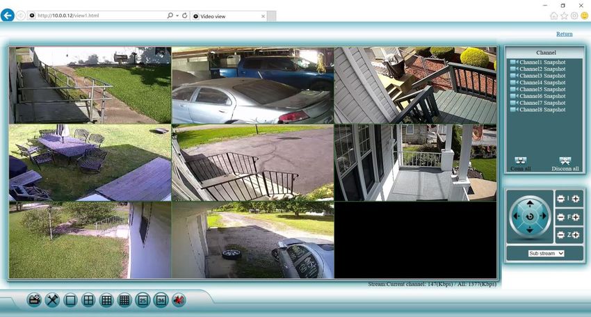
6.2 View your cameras on computer via IE (Internet Explorer) ........................................................................... 69
6.2.1 Local Access via IE (When your computer and NVR are connected to the same network) ........................ 68
6.2.2 Remote Access via IE (When your PC is out of local area network with the NVR, for example: view your
home system from your office computer)............................................................................................................. 71
6.3 View your cameras on computer via CMS PC Client Software ..................................................................... 72
6.4 View cameras on smartphone ......................................................................................................................... 72
3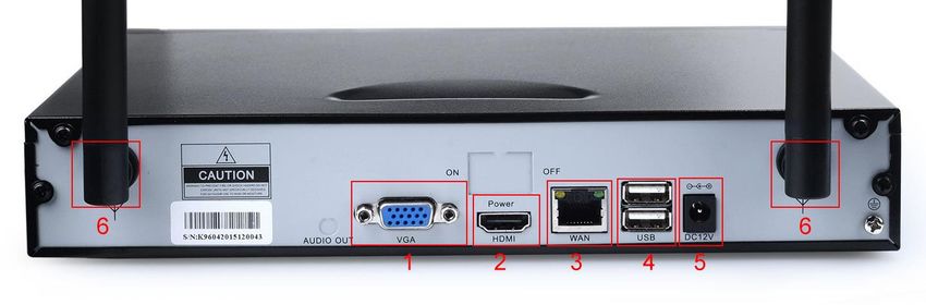
www.xmarto.com
1. Safety Instructions
Use the provided power adapter.
Do not use this product with a power source that applies more than the specified voltage.
Never insert metal into the NVR case or its openings.
Inserting metal into the NVR case may cause electric shock.
Do not operate in wet or dusty areas.
Avoid placing the NVR in areas such as a damp basement or dusty attic.
Do not expose the NVR to rain or use near water.
If the NVR accidentally gets wet, unplug it and contact technical support immediately.
Keep product surfaces clean and dry.
To clean the outside case of the NVR, use a lightly dampened cloth. Do not use cleaning solutions
or solvents.
Do not install near any heat sources.
Do not install the NVR near any heat sources such as stoves, heat registers, radiators or electronics
(including amplifiers) that produce heat.
Unplug the NVR when moving it.
Make sure that the NVR is unplugged before you move it. When moving this device, be sure to
handle it with care.
Make sure there is good air circulation around the NVR.
This NVR uses an internal hard drive, which generates heat during operation for video storage. Do
not block vents on the NVR, as these vents reduce the generated heat while the system is running.
Place this product in well-ventilated area.
Do not attempt to remove the top cover.
If you observe any abnormal operation, unplug the NVR immediately and contact technical
support. Do not attempt to open the NVR to diagnose the cause of the problem.
Handle the NVR carefully.
If you drop the NVR on any hard surface, it may damage the device. If the NVR doesn’t work
properly due to physical damage, contact an authorized dealer for repair.
* It is recommended to use your NVR with an uninterruptible power supply (UPS). Connecting your
NVR and cameras to a UPS allows continuous operation even during power outages. The run-time
duration will depend on the rating of the UPS used.
Chapter
4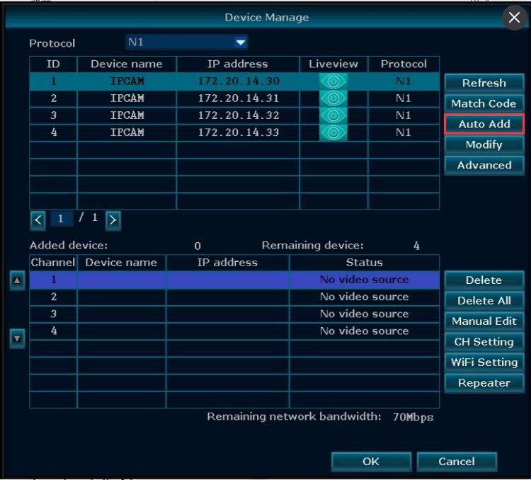
www.xmarto.com

2. Product Overview
2.1 Introduction
The xmartO WNV series network video recorder is our new generation of NVR. It supports wireless
WiFi network video input, real time live view, video playback, and video backup. The NVR system
can be widely used for surveillance of home, business, office, villa, etc.

2.2 System Requirements
Please be sure that your PC/MAC® complies with the following specifications:
• PC Operating System: Windows® 7, Windows® 8/8.1 and Windows® 10
• PC Browser: IE® 8 and above
• MAC Operating System: MAC OS X® 10.7 and above

Please be sure that your mobile device complies with the following specifications:
• Android™: 4.0 and above
• iOS®: 7.1 and above

                                                5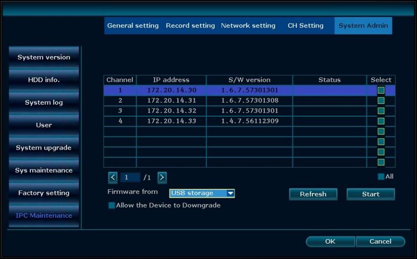
www.xmarto.com

2.3 Specifications

NVR Specifications

                     6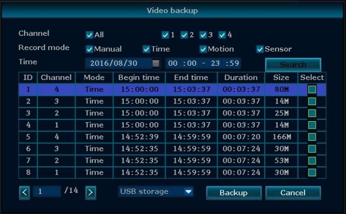
www.xmarto.com

Camera Specifications

2.4 Product Key Features
• Auto-Pair, Plug and Play: NVR and cameras are paired well in default, once you connect NVR to
monitor/TV, plug them to power, you see cameras video on monitor/TV in minutes.

• NVR Built-in WiFi Router: The NVR has a built-in router, providing WiFi for the HD cameras,
so the system won’t use your home network bandwidth. You can use the system to live view, record,
playback and backup even without Internet.

• Dream Liner WiFi Relay: The xmartO Dream Liner technology uses cameras in middle as
repeaters. That way, further cameras connect to closer cameras 1st, and then to the NVR as a group.
This theoretically doubles/ triples the current WiFi distance.

• Full Series High Definition: We have 720p/ 960p/ 1080p HD full series wireless systems for your
choice.

• Easy Remote Access: Supports live view, playback videos remotely from our free mobile apps.
                                                  7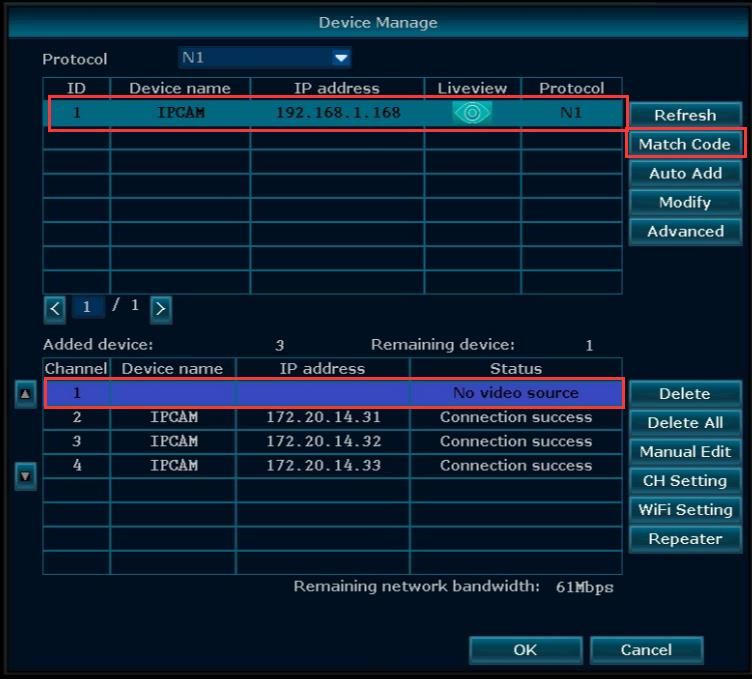
www.xmarto.com
(app for Android devices and iOS devices are available)

• Multiple Recording Modes: Supports manual, continuous, time-scheduled, and motion detection
recording

• VGA and HDMI Video Outputs: Supports connecting to any standalone VGA or HDMI monitor,
or TV.

• Motion Alerts: Supports email alerts with snapshots and mobile push notifications when motion is
detected

• 80ft IR and IP66 Weatherproof: Each camera is equipped with 3 infrared LED arrays which
allows the camera to see up to 80ft at night. Camera works indoor and outdoor.

3. Operation Instructions
3.1 NVR Diagram

                                                      Front View
1. Power Indicator
2. HDD Indicator
3. Connection Status Indicator

                                                  8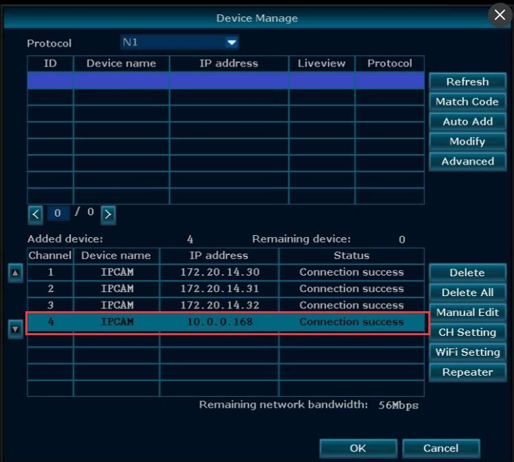
www.xmarto.com

                                             Rear View
                (Images used are for reference only. Your product may vary slightly.)

1. VGA Video Output - Connect the VGA cable from the VGA output port on the NVR to the VGA
input port on your TV/Monitor. (VGA cable not included)

2. HDMI Video Output - Connect the HDMI cable from the HDMI output port on the NVR to the
HDMI input port on your TV/Monitor. (HDMI cable not included)

3. RJ-45 (Ethernet) Port - The RJ-45 port will be used to connect the Wireless NVR to your
modem/router for remote viewing. Please note that your Wireless NVR comes with built-in Wi-Fi for
the cameras to transmit to the NVR. However, you will need to manually connect the NVR to your
modem/router to remotely view on a smart device or PC/Mac®. (If you need to add camera to the
system, or repair camera to NVR, you can also use this Ethernet port to pair camera to NVR.)

4. USB Ports - USB ports allow for the connection of a USB mouse and/or a USB flash drive. You
will connect the included USB mouse to assist you in navigating the NVR’s menu interface. You will
connect a USB flash drive to download video files from the NVR for long term storage or sharing.

5. Power Input - Power input is used to connect the included 12V DC power supply.

6. NVR Antenna Mount - For installation of two included NVR antennas.

NOTE: The maximum number of cameras you can connect to your wireless NVR will be
determined by the number of channels.

                                                 9
www.xmarto.com
3.2 Camera Diagram
1. Infrared LEDs - Cameras see up to 80ft at night
2. Lens - Different lens gives you different viewing angle
3. Image Sensor - 720p/ 960p/ 1080p
4. Infrared PIR Sensor – Detects infrared light
5. Antenna – Receives wifi signals from NVR
6. Camera Mount – Mount the camera
7. RJ-45 Ethernet Port – Pair camera to NVR
8. Audio In – Connect external microphone to camera to record audio
9. Power In – Connect included 12V 1A DC power adapter
NOTE: xmartO cameras with the audio jack support audio. Your camera may not have audio
jack depending on when and where it was shipped.
3.3 Mouse Operation
Live Viewing:
Double-click the left button on any camera view in split-screen mode to bring it to full screen display.
Double-click again to return to split-screen mode.
Right-click to show the NVR main menu.
Right-clicking again will hide the NVR main menu.
10www.xmarto.com
In Setting:
Left-click to make a selection.
Right-click to cancel setting or return to previous screen.
To Enter Values:
Move the cursor to a blank field and click the mouse. A virtual keyboard will appear which supports
numbers, letters and symbols. The Shift function will access symbols in addition to upper case letters.
3.4 Input Method
Image 3
Name Buttons Function
Number 0~9 Type in number 0~9
Character a~z Type in letters a ~ z
Symbols -/._*#@ Type in symbols
Caps caps Switch capital and small letter
Back space ← Delete the character ahead of cursor
3.5 Frequently Used Buttons
OK Save the setting and exit this window (Save and Exit)
Cancel Cancel the setting
Apply Save the setting and stay at the window (Save and Continue)
Copy to Copy the settings of this channel to other channels or all
11www.xmarto.com
4. Installation & Connection
4.1 Installation Precautions
Please refer to below tips while install and use the device:
1. To extend the life of the device, please keep the device away from water, high temperature, and dust.
Use it in a well-ventilated place.
2. Please use SATA hard drive, USB devices and mouse purchased from authentic channels.
3. Before use, please ensure the NVR has correct ground connection. Power source should not exceed
the indicated normal working voltage range in the specs sheet.
4. Do not place near high voltage wires or other sources of electrical interference. Electrical
interference will degrade the quality of the signal.
4.2 Camera Installation
4.2.1 Power the cameras
NOTE: Connect all cameras locally before final placement to ensure that all components
function properly.
1. Locate the antenna included with each camera.
2. Fasten the antenna to the camera.
3. Locate the camera power adapter included and connect it to a surge protector, UPS or wall outlet.
4. Connect the camera power adapter to camera’s power port.
5. Repeat for each camera.
4.2.2 Mount the cameras
Camera distance from NVR. Your wireless IP cameras will reach up to 3-400ft. wirelessly.
Therefore, proper placement of the wireless NVR in your home will help ensure you achieve
12www.xmarto.com
maximum coverage.
Do not place near high voltage wires or other sources of electrical interference. Electrical
interference will degrade the quality of the signal.
Place camera out of reach to avoid vandalism.
Avoid direct exposure to weather. Do not place the camera where rain or snow will hit the lens
directly nor should the camera be placed so that the sun or bright light shines directly into the lens.
Your camera is weatherproof, but it will not work when submerged in water. Ensure that all power
and video connections are not directly exposed to water and are protected from the elements.
The mounting surface must hold at least four times the camera’s total weight.
1. Locate a camera and choose a location where you would like to mount the camera.
2. Indicate screw positions by marking three holes on the surface where you plan to mount the camera,
using the holes in the camera base as a guide.
3. Using a drill bit slightly smaller than the included screw anchors, drill into the mounting surface
using the guide marks you placed in the previous step.
4. Insert the screw anchors.
5. Line up the camera base holes with the screw anchors. Holding the base in place, insert screws and
tighten until secure.
6. Once the base is screwed in place, make sure that the camera is securely mounted by placing gentle
pressure on the mount.
7. Adjust the camera housing to point in the direction of the area you would like to monitor.
13www.xmarto.com
4.3 NVR Installation
4.3.1 Connect your wireless NVR
1. Connect the two included antennas to your wireless NVR. This will ensure you achieve the
maximum wireless range for transmission from your wireless cameras.
2. Connect NVR to a standalone PC monitor or TV using VGA or HDMI cable (VGA & HDMI cable
not included).
3. Plug one end of the included Ethernet cable into the WAN port on the back of the Wireless NVR.
4. Plug the other end of the Ethernet cable into a port on the back of your router.
5. Connect the Wireless NVR to power using included 12V 3A DC power adapter.
You should see each camera appear on your TV/Monitor. You may now proceed to install your
Wireless NVR cameras in the desired location.
If you do not see cameras appear on your TV/monitor, you must have a NVR resolution compatibility
issue. Please contact xmartO support at support@xmarto.com for help.
Install Antennas for NVR
Connect NVR to monitor/TV
14www.xmarto.com
Connect NVR to router for remote access
Connect NVR to power
4.4 Install Hard Drive
You’ll need to add a SATA HDD to the wireless NVR and format it to start recording.
If your system comes with hard drive pre-installed, then you only need to format the hard drive to start recording.
1. Unplug your wireless NVR from power, unscrew and remove the NVR top cover.
15www.xmarto.com
2. Connect the SATA power and data cables from NVR to the corresponding ports on your hard drive.
3. Place the hard drive into the NVR. Any cables should cross up over the HDD.
4. Holding the hard drive and NVR, gently turn it over and line up the holes on the hard drive with the holes on the
NVR. Using a screwdriver, screw the provided screws into the holes. Assemble the cover.
16www.xmarto.com
4.5 Camera Mounting Spots
1. Mount the cameras anywhere within the Wi-Fi range, plug them to power with included power
adapters (smaller ones are for cameras).
2. The cameras should start to stream videos to NVR within 1 minute.
3. If it does not display video on the NVR’s screen, the distance should be too long or there are too
many obstacles. Please move the cameras closer to the NVR.
4.6 Antenna Mounting Tips
Correct Wrong
The NVR’s antennas radiate signals to all around. The signal pick-up is best while antennas are on
same height and parallel. If the cameras cannot be at same height with NVR, please keep their
antennas parallel.
Suggestions to get better WiFi connection between cameras and NVR:
http://www.xmarto.com/helpcenter/?/article/1
17www.xmarto.com
5. Getting Started
When your NVR is powered on it will display the xmartO logo while initializing.
5.1 Login
After initialization, the system will pop out below login interface. Users must login to do further
operations.
Default Username: admin
Default Password: empty, means no password, leave it blank
5.2 Setup Guide
After login the system, it will enter Setup Guide automatically, and guide you to do basic settings. You
can also right click your mouse or click “Cancel” to skip it.
18www.xmarto.com
If you don’t want to go through Setup Guide once again when system reboots, please keep “Enable
Setup Guide When System Reboot” unchecked.
5.2.1 General setting
Allow the user to set up NVR’s time zone, date and time, language, and keypad type. Click “Next” to
continue after finish your settings.
5.2.2 Networking
Allows users to connect the NVR to Internet for remote access.
Users can either check DHCP to allow NVR obtain IP address from router automatically, or
manually set an IP address for the NVR.
19www.xmarto.com
Auto Setup:
Click Auto Setup, NVR will obtain IP address from router automatically and connect to
Internet. Once the Device ID shows Online and Network Status shows Healthy Network, your
NVR is connected to Internet and is available for remote access.
Manual Setup:
Click Manual Setup, you’ll be directed to below Network setting interface, where allows you to
set an IP address for the NVR, as well as other network parameters. To setup NVR network
settings manually, you need to uncheck DHCP first. Remember to click Apply or OK to save the
setting after complete it.
20www.xmarto.com
5.2.3 HDD Setting
It displays information of current hard drive installed, including the hard drive model, capacity,
used, status and format status.
Hard drive needs to be formatted to start recording.
To format the hard drive, select it and click “Format”. It will take some seconds to format the
hard drive.
When hard drive is successfully formatted, the status will show ‘Formatted’. (You will lose all
data on the hard drive if you format it. So please make sure to back up the data before
formatting your hard drive.)
5.3 Startup/ Login/ Logout/ Reboot/ Close screen
display/ Shutdown
5.3.1 Startup
Note:
· Please ensure the power input voltage fit the NVR’s requirements and the NVR has correct ground
connection.
· Unstable power source may cause unstable working status or even damage the NVR. If you have
unstable power source in your area, please use voltage-stabilized power source.
Tips:
21www.xmarto.com
· Before power on the NVR, please connect the NVR to a monitor or TV using VGA or HDMI
cable.
Steps of startup the system:
1. Connect NVR to a standalone monitor/TV via VGA or HDMI. (Laptop cannot be used as a
monitor.)
2. Plug NVR to power using included 12V 3A DC power adapter, you’ll hear a beep
and the power indicator light on NVR front panel will light up.
3. If monitor is getting video output from NVR, you should see the starting page with
xmartO logo. If not, please check connection.
NOTE: If you cannot get any display on TV, you have resolution incompatibility
issue. The NVR’s default resolution is 1280 x 1024, which does not work with some
of screens. You need another screen to display cameras, or change NVR’s resolution
online to match with your current screen.
Here is how to change NVR resolution online:
http://www.xmarto.com/helpcenter/?/article/10
5.3.2 Logout
If you want to log out while using the system, right click your NVR mouse to pop out NVR main
menu, then click “Exit System”, and choose “Logout”.
If you want the system to auto logout, please go to “System setting” – “General setting”, enable the
“Auto Logout”, click “Apply” to save this setting. System will auto logout if there is no operation
within 1 minute. Username and password will be required for next login.
22www.xmarto.com
5.3.3 Reboot
If you want to reboot the system while using it, right click your NVR mouse to pop out NVR main
menu, then click “Exit System”, and choose “Reboot”. System will reboot immediately.
5.3.4 Close screen display
If you want to close the screen display while using it, please right click your NVR mouse to pop out
NVR main menu, then click “Exit System”, and choose “Close screen display”. System will stop
displaying camera videos on screen. Double click the left button of your mouse will get it back.
5.3.5 Shutdown
If you want to shut down the system, please right click your NVR mouse to pop out NVR main menu,
then click “Exit System”, and choose “Shutdown”. System will release power and pop out message
“Now you can power off the device”. Unplug your NVR from power, and the system will shut down
completely.
5.4 Device Manage
Manage your cameras’ connections with the NVR. In Device Manage interface, you can add new
cameras to NVR, re-pair cameras that lost connection to NVR again, delete cameras from their current
channels and re-pair.
5.4.1 Add Device (Pair Camera to NVR)
Pair new add-on camera to NVR, repair lost camera to NVR, pair camera to work wired when they are
installed out of NVR’s WiFi range….
5.4.1.1 Add new camera to NVR (Match Code)
Function: Pair the camera to NVR to work wirelessly.
The main function of “Match Code” is to pair the IP cameras to NVR, transmit NVR’s WiFi hotpot
and password to IP cameras, thus IP cameras connect to NVR automatically and transmit the video
signals to NVR wirelessly.
Applies to the situations that add new add-on camera to your system, replace old camera in your
system, and repair lost camera to NVR.
23www.xmarto.com
Detailed Instructions: http://www.xmarto.com/helpcenter/?/article/9
1) Connect the camera to your NVR’s Ethernet port with a network cable. Plug the camera to power.
The Ethernet port on the camera cable end will light up.
2) Right click your NVR mouse to pop out NVR main menu, then click Device Manage. Click
“Refresh” on upper right and wait for a moment, you’ll see the camera displays in upper box,
with IP address 192.168.1.168. (192.168.1.xxx is camera’s wired IP address, so when you connect
the camera to NVR using network cable, you see the camera show in upper box with this wired IP
address.)
24www.xmarto.com
3) Select the camera in upper box, and select an unoccupied channel from bottom box, click “Match
Code”. Wait for them to pair, once finish, you shall see the camera display video on monitor, and
the channel status changes to Connect Success, with assigned IP address 172.20.14. xx. (172.20.14.
xx is camera’s wireless IP address, when it is paired to work wirelessly with NVR, it will be
assigned with a wireless IP address 172.20.14.xx.)
4) You can then disconnect the camera from NVR and move it to anywhere you want. When it gets
power, it will automatically connect to NVR and display video on monitor. (Camera needs to be in
the NVR’s Wi-Fi range)
More details can be found here: http://www.xmarto.com/helpcenter/?/article/9
Channel Status:
Connect Success: Camera is paired to NVR successfully; you should be able to see the camera
video on your monitor.
No Video Source: Unoccupied channel, no camera is paired to this channel, you can pair a new
camera to this channel.
IPC Disconnect: Camera is paired to NVR but not connected successfully. The reasons vary,
please contact xmartO support for solution.
5.4.1.2 Configure Camera to work Wired
Function: If any of your cameras need to be mounted out of NVR’s WiFi range, you can hard wire
cameras to router with network cables, and pair them to NVR to work wired.
25www.xmarto.com
1) Right click your NVR mouse to pop out NVR main menu, then click Device Manage. Select the
channel that you want to hard wire from bottom box and click Delete. The channel will become
unoccupied, with status No Video Source.
2) Connect the camera to your router’s LAN port with a network cable. Plug the camera to power.
The Ethernet port on the camera cable end will light up.
3) Go to Device Manage interface, click “Refresh” on upper right, you’ll see the camera show in
upper box.
4) Select the unoccupied channel from bottom box, then double click the camera in upper box. This
will add the camera to NVR. And once finish pairing, you shall see the camera display video on
monitor, and the channel status change to Connect Success.
5) Now the camera is working wired, please keep the camera hard wired to router to get it work.
NOTE: Since the camera is paired to work wired, it needs to be keep hard wired to router with
network cable to work. And the channel IP address is different from other wireless channels.
Usually the channel IP address for wired camera is 192.168.1.xx or 10.0.0.xx, which is in the same
network segment of your router.
More details can be found here: http://www.xmarto.com/helpcenter/?/article/14
26www.xmarto.com
5.4.1.3 Auto Add
Function: Find all cameras back quickly after upgrading NVR firmware
Auto Add allows you to add all cameras back with only one click.
If cameras do not come back automatically after upgrading NVR firmware, or cameras lost connection
with NVR but their pairing relationship are still existed, you can go to Device Manage and click Auto
Add to find all cameras back easily.
Detailed instructions:
1) Right click your NVR mouse to pop out NVR main menu, then click “Device Manage”. You’ll see
all cameras show in upper box, with IP address 172.20.14. xx. And all channels are showing No
Video Source, as shown in below picture.
2) Click “Auto Add”, you’ll then see all cameras are added to NVR channels and all of them are
displaying video on monitor.
27www.xmarto.com
NOTE: Our latest NVR firmware supports finding cameras back automatically after upgrading
firmware. So usually after upgrading NVR firmware, cameras will come back automatically after
reboot, no need to do any settings to add them back.
5.4.2 Modify Device
Function: Modify camera information.
Operation Steps:
1) Right click the mouse to pop out NVR main menu, then click Device Manage to enter the interface.
Select a camera in upper box and click Modify. You’ll see below interface.
28www.xmarto.com
2) You can set the camera information here. Click OK to save the settings and exit.
5.4.3 Advanced
Function: Supports multiple network segment search, allows for repeated add and intelligent add.
Operation Steps:
1) Right click the mouse to pop out NVR main menu, then click Device Manage – Advanced. You’ll
see below interface.
Tips:
Enable “Multiple Network Segment”, system can search wireless IP cameras that are in different
segment as NVR.
Enable “Repeated Add”, system will allow users to add one camera to multiple channels.
Enable “Intelligent Add”, system will assign a new valid IP address for the camera if it finds that
the camera’s current IP address is abnormal (IP address conflicts or camera’s IP address is not in
the same segment as NVR).
29www.xmarto.com
5.4.4 Delete Device
Function: Delete camera from its current NVR channel.
“Delete” allows you to delete one channel at a time.
“Delete All” allows you to delete all channels at once.
Operation Steps:
1) Right click the mouse to pop out NVR main menu, then click “Device Manage” to enter device
manage interface.
2) Select one channel from bottom box and click “Delete”. The camera will be deleted from this
channel, and you shall no longer see the camera video on your monitor. This channel will become
unoccupied, and show No Video Source under Status.
NOTE:
Click “Delete All” button will delete all the IP Cameras that are added to the NVR. We suggest users
use this button cautiously, because after deleting all cameras from the NVR, you need to hard wire
them to NVR to repair them manually, which is not easy.
5.4.5 Manual Edit
Function: Edit channel information, including protocols, IP address, port number, username,
password, and stream type.
30www.xmarto.com
Operation Steps:
1) Right click the mouse to pop out NVR main menu, then click “Device Manage” to enter device
manage interface.
2) Select one channel and click “Manual Edit”, you shall then see below Interface. Check Enable,
you’ll be able to change the channel information here.
5.4.6 Repeater
Function: Setup Dream Liner feature to boost the wifi signal of xmartO system.
The xmartO Dream Liner technology uses cameras in middle as repeaters. That way, further cameras
connect to closer cameras 1st, and then to the NVR as a group. This theoretically doubles/ triples the
current WiFi distance.
Operation Steps:
1) Right click your NVR mouse to pop out NVR main menu, click Device Manage and then click
Repeater. You’ll enter the repeater interface to setup Dream Liner.
31www.xmarto.com
2) Click “+” behind the channel that you plan to use it as repeater, and add the channel that has weak
Wi-Fi signal to this one.
For example, click “+” behind CH1, add CH2 to connect to CH1, CH1 and CH2 will lose
connection for some seconds and connect back automatically. Click "Refresh" to check if the Dream
Line is successfully built.
NOTE:
If you have multiple lines to build, try build one each time to avoid system freeze up. If it happens
your system freezes up during Dream Line building, wait patiently till it goes back to operable
status. If it stays freezing, unplug power and enter the repeater setting page again.
Cameras and NVR stay connected to constant power.
32www.xmarto.com
NVR needs to stay ONLINE.
Move cameras to the same room with NVR, or close enough to ensure they receive data and
command from NVR constantly. This will ensure you setup repeater successfully.
In Repeater interface, only channels with green dotted lines are available for repeater setup,
channels in red dotted lines are not.
Dream Liner only works for wireless cameras. Wired cameras can’t be used as repeaters.
Need more information about Dream Liner? Check here: http://www.xmarto.com/dreamliner
5.5 Channel Setting (CH Setting)
5.5.1 Encode Setting
Function: Set the IP Camera information, including stream, resolution, rate, frame rate, frame rate
interval, H.264 coding grade, etc.
Operation Steps:
1) Right click the mouse to pop out NVR main menu, then click Device Manage – CH Setting, you’ll
see below interface.
2) Switch the channel, and you can check all channels’ information here.
Tips:
Users are not allowed to edit the channel information here.
33www.xmarto.com
5.5.2 Channel OSD
Function: Adjust the cameras’ color, change the cameras’ name, enable system status display and
cameras’ connection status, and where to place status icons.
Operation Steps:
1) Right click the mouse, then click System setting – CH Setting – Channel OSD, you’ll see below
interface.
2) Click “Color adjust”, users will be directed to the interface to adjust your cameras’ color, including
hue, brightness, saturation and contrast.
3) Camera title allows users to change the camera name of each channel.
4) Enable “Status Display” and “Connection Status”, the system status and cameras’ connection
status will be displayed on the monitor.
5) Display setting allows users to decide where to place the status icons.
Tips:
When change camera name, please keep in mind that no space and no special symbols are allowed
in the name. Keep only one word for the camera name. For example, you can not name the camera
as home camera, instead, you need to name it as homecamera or home.
5.5.3 Bitrate
Function: Check the cameras’ bitrate information.
Operation Steps:
34www.xmarto.com
1) Right click the mouse to pop out NVR main menu, then click System setting – CH Setting - Bitrate.
You’ll see below interface.
5.5.4 Channel Details
Function: Check the cameras’ name, resolution, bitrate, frame rate and firmware version.
Operation Steps:
1) Right click the mouse to pop out NVR main menu, then click System setting – CH Setting –
Channel Details, you’ll see below interface.
35www.xmarto.com
2) Click Refresh, it will search and show all cameras that connected to the NVR.
5.5.5 IP Camera
Function: Set the mounting type for panoramic camera.
Operation Steps:
Right click the mouse to pop out NVR main menu, then click System setting – CH Setting – IP camera,
you’ll see below interface.
36www.xmarto.com
Tips:
The mounting type option only works for panoramic cameras.
It supports panoramic cameras that support N1 protocol.
5.6 Network Setting
5.6.1 Network Setting
Declaration: To remote access your cameras from computer and smartphone, you need to connect the
NVR’s WAN port to your router’s LAN port with a network cable. After doing this, your NVR will get
online. Only when the NVR is online, you can remote access your cameras.
Default NVR IP address: 192.168.1.114
Operation Steps:
1) Connect the NVR’s WAN port to your router’s LAN port with a network cable.
2) Right click the mouse to pop out NVR main menu, then click System setting – Network setting,
you’ll see below interface.
37www.xmarto.com
3) Check “DHCP”, your NVR will obtain IP address from router directly.
4) Click “Apply” to save the settings, and click “OK” to exit.
Tips:
DHCP is usually checked in default.
If your NVR is connected to Internet, the “Network Status” will show “Healthy Network”.
If check DHCP cannot get your NVR online, you can uncheck it and manually set the IP address
for NVR to get it online.
Detailed Feature List:
Name Function Description Note
IP Address Set NVR’s IP address, user can set the IP address Uncheck DHCP, user will be able
manually to set IP address for NVR
Subnet Mask Set the Subnet Mask
Gateway Set the Gateway
MAC Address Set the MAC Address Avoid using same MAC Address in
LAN
Web Port Transmit video signal and other control signals, Port 80 is used for web, PC client
default is 80 and Mobile
DHCP Check DHCP, NVR will obtain IP address from NVR When DHCP is checked, user can
automatically not set NVR IP address manually
5.6.2 DDNS
Function: If you don’t have a static IP, using DDNS (Dynamic DNS) to access your device via
domain name can effectively solve the problem caused by dynamic IP.
38www.xmarto.com
Tips: this is only necessary when you are not satisfied with the Cloud Device ID method. DDNS does
not rely on Cloud streaming so it may give you smoother remote connection.
Operation Steps:
1) Right click the mouse to pop out NVR main menu, then click System setting – Network setting –
DDNS, you’ll then see below interface.
2) Check “Enable” to enable DDNS function.
3) Enter the Domain Name, Username and Password. Click “Test” to test your settings.
4) Click “Apply” to save the settings, and click “OK” to exit.
Tips:
Currently supports domain providers: popdvr, 3322, changeip, no-ip, dyndns. Please apply for
your own DDNS from these providers before you use it.
Domain Name information cannot be edited if “Enable” is unchecked.
5.6.3 E-Mail
Function: Set up motion detection email alerts.
Operation Steps:
1) Right click the mouse to pop out NVR main menu, then click System setting – Network setting –
E-Mail, you’ll see below interface.
39www.xmarto.com
2) Check “Enable” to enable the email notification function.
3) Enter the information of SMTP Server, Port, Username, Password, Sender, Recipient, etc., as
shown in below screenshot.
4) Click “Test” to see if it is set successfully, if yes, click “Apply” to save settings, and click “OK” to
exit.
Detailed Feature List:
Function Name Function Description
SMTP Server The SMTP server of your sender email account, correct format: smtp.mail.yahoo.com
Port The port number of the SMTP server
User Name Username of your sender email account
40www.xmarto.com
Password Password of your sender email account
Encryption Type Leave it blank in default, if failed on test, then change to SSL
Sender Full email address of sender email account
Recipient Full email address of receiver email account, you can set up to two recipients
Delay The time delay on receiving email alerts
Health Message The frequency of receiving email in normal running/operation
Interval
Tips:
To receive email alerts, you need to check “E-Mail Notification” under Video Detection also.
Health Message Interval only takes effect when you check “Enable”.
If failed to pass the test email, please assure that you’ve enabled SMTP service for your email
account.
Please refer to http://www.xmarto.com/helpcenter/?/article/2 for a more detailed email setup
guide.
5.6.4 PPPoE
Function: Supports access internet via dial-up
Operation Steps:
1) Right click the mouse to pop out NVR main menu, then click System setting – Network setting –
PPPoE, you’ll see below interface.
2) Check “Enable”, enter the Username and Password provided by ISP.
3) Click “Apply” to save the settings, and click “OK” to exit.
Tips:
41www.xmarto.com
PPPoE Function: for enable PPPoE, allowing access internet via dail-up; for disable
PPPoE
5.6.5 3G
Function: This is to enable users who don’t have Internet service to use USB data stick to connect the
NVR to Internet.
Operation Steps:
1) Right click the mouse to pop out NVR main menu, then click System setting – Network setting –
3G, you’ll see below interface.
2) Check “Enable” to enable 3G Module.
3) Enter the information of Dial-Number, APN, PIN, Username, Password, etc.
4) Click “Apply” to save settings, and click “OK” to exit.
5.6.6 WiFi Setting
Function: This enables users to change settings of the NVR’s Wi-Fi hotspot and password; and some
other router related settings.
ESSID: The default Wi-Fi hotspot name of the NVR.
Password: The default password of the Wi-Fi hotspot; auto generated by the system.
Operation Steps:
1) Right click the mouse to pop out NVR main menu, then click System setting – Network setting –
42www.xmarto.com
WiFi setting, you’ll see below interface.
Tips:
Change the hotspot name or the password will cause losing connection with cameras; please
restore to factory settings if you lose camera connections; or follow 4.3.2 to add cameras to the
NVR.
If you plan to install two systems in the same room, you can try to change the WiFi chancel to
avoid interference.
On right of WiFi setting interface, the rate indicates cameras’ connection strength. If rate is above
30, it’s considered to be good connection, while if rate is under 25, it’s considered to be weak
connection.
5.6.7 PTZ Setting
5.6.7.1 PTZ Parameter Setting
Prerequisites:
Before trying to control the speed dome or PTZ, you need to make sure that the decoder of this PTZ
has already connected to NVR, and you need to set the parameters for the PTZ in NVR.
Operation Steps:
1) Right click the mouse to pop out NVR main menu, then click System setting – CH Setting – PTZ
setting, you’ll see below interface, as shown in below image.
43www.xmarto.com
Operation Guide as below:
Operation Target Function Description
Channel Choose the channel you want to set PTZ
Protocol Choose the correct protocol of this PTZ
Device Address Enter the specified decoder address
Baud Rate Choose the right baud rate to match with this PTZ’s baud rate
Copy to Choose the channel you want to copy the settings and click “Copy to” to apply
current channel’s settings to other channels
5.6.7.2 PTZ Control Operations
Operation Steps:
1) Double click the channel you want to set in main preview screen.
2) Right click mouse in that channel’s preview interface and choose the PTZ control, you’ll then see
below image, as shown in below image.
Operation Explanation:
: Control the PTZ to rotate upward
: Control the PTZ to rotate downward
: Control the PTZ to rotate leftward
: Control the PTZ to rotate rightward
44www.xmarto.com
: Control the PTZ to rotate 360 degrees automatically
+: Adjust Zoom+, Focus+, Iris+.
-: Adjust Zoom-, Focus-, Iris-.
5.6.7.3 PTZ Auto Cruise Setup
Operation Steps:
1) Right click the mouse to pop out NVR main menu, then click System setting – CH Setting – PTZ
setting.
2) Click “?” at the right of “Preset” to enter the control interface to set presets.
3) Choose presets and set rotation direction.
4) Right click mouse to back to the setup interface, set the “Keep time”.
5) Click “Add” to finish setting this preset.
6) Repeat above 2-5 steps to add other presets.
7) Setup complete, check “Tour Start” to modify the rotation speed accordingly, as shown in image
40.
8) Right click mouse to back to setup interface, click “Apply” to save settings.
Tips:
Presets are the tour spots, the PTZ tour from small to large spots automatically.
Keep time is the time length that the PTZ will stay at a preset.
Speed is the rotation speed that the PTZ tour from one preset to another preset.
5.7 Record Setting
5.7.1 Manual Record
Function: Manual recording allows users to turn on/off recording easily and quickly.
Operation Steps:
1) Right click the NVR mouse to pop out NVR main menu, choose “Manual record”.
45www.xmarto.com
2) Select the channels you want to record.
3) If you want all the channels to record, then check “All” or click “All ON”.
4) If you want to disable manual record for all channels, click “All OFF”.
5) Click “OK” to finish the manual record setup. As shown in below image.
Tips:
Recording Priority: Alarm Recording > Motion Detection Recording > Manual Recording > Time
Scheduled Recording
5.7.2 Time-scheduled Recording
Function: Time scheduled recording enables the NVR to record 24/7 continuously or record in
specified time periods only.
Operation Steps:
1) Right click mouse to pop out NVR main menu, then click System setting – Record setting –
Record Plan. You’ll see below interface, as shown in below image.
2) Choose the Channel and set Weekday from drop-down list.
3) Schedule the times period, and check “Time”. You can set 4 times periods for each channel.
4) Click “Copy to” if you want to apply the settings to other channel or all channels.
46www.xmarto.com
5) Click “Apply” to save the settings and click “OK” to exit.
Tips:
You can set up to 4 times periods for each channel per your specific recording needs.
If you want the NVR to record 24 hours continuously, then you only need to set 1 time period,
from 0:00 - 23:59, and keep the other schedules blank.
Different time periods will show in different color for easy differentiation.
You can combine the various recording modes on each channel. As shown in below image.
5.7.3 Motion Detection Recording
Function: Motion detection recording enables NVR to record only when motion or movement is
detected.
Operation Steps:
1) Right click mouse on monitor to pop out NVR main menu, then click System setting – Record
setting – Record Plan. You’ll see below interface, as shown in below image.
2) Set the Channel and Weekday from drop-down menu.
3) Keep the default schedule 1 time period and check “Motion”.
47You can also read