Sliding Closer NSC Series - Horizontal
←
→
Page content transcription
If your browser does not render page correctly, please read the page content below
Cat.NO.    K-110

                                                                                                                  ISO9001 CERTIFICATED (QC99J1026)
                                                                                                                   SHIRAKAWA NITTO KOHKI Co,.LTD.

Horizontal

Sliding Closer
NSC Series
    Series
New-generation sliding door closers developed with user-friendly technologies.
We propose a new style of door opening/closing.

                                                      ● Elderly nursing home (dining hall door)

                                                                                                  ● Hospital/medical care center
                                                                                                    (consultation/examination room door)

       ● Hospital/medical care center (toilet door)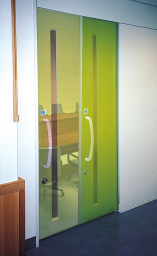
Horizontal Sliding Closer
Developed with User-
Friendly Technologies
These newly developed door closers are friendly to elderly
persons and children. Doors equipped with these door closers
can be easily opened even by gentle force and close quietly
and properly at a favorite speed.
Horizontal sliding closers New
NSC Series
When you release the
door, it closes quietly and
slowly. It closes
automatically, saving you
the trouble of closing it.
Increased
space savings
are provided.
■ Swing door closer ■ Sliding door closer
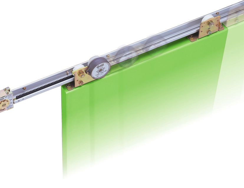
Sliding door closer system for eliminating the existence
of an unusable space and offering increased
safety assurance
Reinforced resin door rollers Hanger (rear) Door stopper
and aluminum rail are used
to make the door opening
/closing motion quiet. Rail
Hanger (front)
Door
● Door opening force: 3.9 N (required for
Control device
initial motion when the door weight is 40
The endless, fluid friction resis- kg)
tance system (patent pending)
is employed to offer a compact, ● Spiral spring type closing drive
lightweight, long-life closer.
● Fluid friction resistance control device
The door closing speed can
easily be adjusted for a
● Applicable frame dimensions: 120 mm
The following options are available for keeping desired level. high x 70 mm thick
the door opened.
• Full-opening stopper Pull spring The temperature compensation ● Applicable door: weight, 10 to 80 kg;
• Free stop unit (stop at any position) Options function (patent pending) is maximum stroke, 1500 mm
incorporated so that the closing
• Time stop device speed remains virtually the The bathroom door type (stainless steel)
Sliding closers having a heat/smoke detection coordination function are also available. same even when the ambient
temperature changes. is also available.
Increased ease of maintenance is provided.
■ Door opening force data
NSC-23R-22
Model
Door opening
force (N)
Rail length Door weight...60kg
22 : 2200 mm
Door weight...50kg
28 : 2800 mm
34 : 3400 mm
Opening R : Right-handed Door weight...40kg
orientation opening
L : Left-handed opening
Door weight...30kg
Door weight 23 : 10 ~ 30 kg
36 : 30 ~ 60 kg
Horizontal sliding closer 48 : 60 ~ 80 kg
Opening length (mm)
1
■ Specifications
Model NSC-23R/L-22/-28/-34 NSC-36R/L-22/-28/-34 NSC-48R/L-22/-28/-34
Applicable
Weight 10 30 kg 30 60 kg 60 80 kg
door Width 700 1200 mm 1200 1400 mm 1400 1600 mm 700 1200 mm 1200 1400 mm 1400 1600 mm 700 1200 mm 1200 1400 mm 1400 1600 mm
Rail L = 2200 mm L = 2800 mm L = 3400 mm L = 2200 mm L = 2800 mm L = 3400 mm L = 2200 mm L = 2800 mm L = 3400 mm
Maximum stroke 1500 mm 1500 mm 1500 mm
Closing drive system Spiral spring type Spiral spring type Spiral spring type
Control system Fluid friction resistance type Fluid friction resistance type Fluid friction resistance type
Control time 8.0 to 15.0 sec 8.0 to 15.0 sec 8.0 to 15.0 sec
(at a door opening distance of 900 mm) (at a door opening distance of 900 mm) (at a door opening distance of 900 mm)
Durability More than 1 million open/close operations More than 1 million open/close operations More than 1 million open/close operations
Pull spring PS-02R/L PS-03R/L PS-04R/L
Spring's pulling force 1.3 2.1 N 1.8 3.9 N 3.4 4.7 N
Initial door
opening force 2.16 2.84 N 3.24 5.39 N 5.59 7.06 N
■ Part arrangement diagram (standard set parts/options)
2 -3
2 -2
1
20
2 -1 10
6 11 21
5 17
9
7
3
16 12 2
14
13
1 -1 1 -2
3
1 -3 8
15 4 19 1 -3
18
4 -2
4 -1
5
Standard parts
No. Part name Qty. No. Part name Qty.
1 Rail 1 18 M8x30 pan head screw 2
2 Control device 1 19 Spring washer, 8 mm nominal 2
3 Pull spring 1 20 M4x10 pan head screw 3
4 Pull spring mounting bracket 1
5 Control rack 2
6 Noise suppression rubber 1 Options
7 Rack retainer 2 No. Part name Qty.
8 Hanger, front 1 1 -1 Door stopper 1
9 Hanger, rear 1 1 -2 Door stopper supporting plate 1
10 Door stopper 1 1 -3 M4x10 pan head screw 3
11 Door stopper supporting plate 1 2 -1 Stop equipment 1
12 M5x25 pan head screw (for a rail length of 2200 mm) 8 2 -2 Stop plate 1
13 M5x12 pan head screw 2 2 -3 M3x5 pan head screw 2
14 M3x 5 pan head screw 1 3 Height adjusting plate (t=1.0, 0.5) 1
15 M3x 6 pan head screw 2 4 -1 Wooden door plate 2
16 M3x 5 pan head screw 2 4 -2 φ5x30 countersunk wood screw 8
17 M8x25 hex head bolt 4 5 Guide roller (φ16, 25, 30, 35) 1
10 and 12 pieces respectively for rail lengths of 2800 mm and 3400 mm
2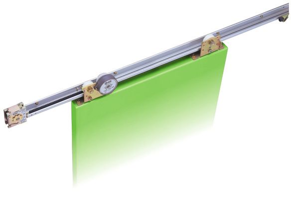
■ Setup view of horizontal sliding closer
70 mm or more
(frame inside dimension)
75
Door stopper
61.5 Pull spring Hanger (front) Control
Door stopper
supporting plate
(frame inside dimension)
PS-02R
LOT NO.
1425
120 mm or more
SPEED
F S
110
105
TYPE NSC-AR
No. 0000
57.5
10
34.4
32.5
157 61.5
30 120 120
D
Overlap 10
DH
H
Door end (opening side)
Guide roller
or more
30 mm
31
7
■ Pull spring ■ Control device
48.5
31
26 17.5
9 6
4
1 ø8
ø 94
65 1600 wire stroke
4.6
ø8
ø71
ø16
PS-02R
LOT NO.
1425
50 Output refe-
76
65
rence position 6
23.5 2-ø5.2
Pan head screw M3x5
6
Mounting bracket
Pull spring
(Mounted at the time of installation)
Bracket mounting screw M3x6
4.5
SPEED
F S
8.5
35.5
28
TYPE NSC-AR
No. 0000
11
3
5.5
8
NOTE 1: This drawing illustrates the right handed opening type NOTE 1: This drawing illustrates the right handed opening type
The left-handed opening type is left-right symmetrical to the illustrated one. The left-handed opening type is left-right symmetrical to the illustrated one.
3Sash inner width W
Rail length L=W−150 75
device Hanger (rear) Door stopper supporting plate Stop plate Door stopper
Stop coil Rail
180
120 120
DW
Margin 10
Door end (closing side)
NOTE 1: This drawing illustrates the sliding closer for right handed opening.
The left-handed opening closer is left-right symmetrical to the illustrated one.
NOTE 2: This drawing shows a sliding closer that is installed when the door opening
end overlap is 10 mm and the door closing end margin is 10 mm.
■ Hanger (front) ■ Hanger (rear)
136 136
8 120 8 120
28
28
2-ø9
2-ø9
32 25.5
80
13 19.5 42
62
51
10
0.5
12
24.5
2-ø2.6
)
2
36
81.5
(R
42
41
70
2-M5 2-M5
22.5
ø4.5 M8
81.5
41
75
23.5
2-ø4.5
4
22 68
45
4
M8
NOTE 1: This drawing illustrates the right handed opening type NOTE 1: This drawing illustrates the right handed opening type
The left-handed opening type is left-right symmetrical to the illustrated one. The left-handed opening type is left-right symmetrical to the illustrated one.
4■ Rail mounting hole tapping diagram (right-handed opening type) M5(P=0.8)
Adjustment dimension: 300 mm or less
125 Equally spaced at 300 mm intervals 125
57.5
120 mm or more
Sash inner width W
75 Rail length L=W−150 75
10
DH
H
Right-handed opening
7
Margin Overlap
10 Effective opening WO 100 or more
DW DS=(DW-100) or less
■ Door stopper/control rack/stop plate setup dimensions
75 120 483.5 74 49 75
(Adjustment range 25~120)
17.5 T-groove center
75 8 15 10 426 (213x2 pcs.) 30 Running track center 15 33 75
12.2
12.2
2 46 46 27
Door end (opening side) Rack retainer Door end (closing side)
Rack retainer Control rack Noise suppression rubber
Overlap 10 Margin 10
NOTE 1: This drawing illustrates the right handed opening type.
The left-handed opening type is left-right symmetrical to the illustrated one.
NOTE 2: This drawing shows a sliding closer that is installed when the door opening
end overlap is 10 mm and the door closing end margin is 10 mm.
5■ Installing the pull spring ■ Adjusting the closing force and speed
Mounting the pull spring mounting bracket Adjusting the closing force
● As shown below, insert the pull spring mounting ● If you encounter the following situations, make
bracket into the T-groove in the rail, and secure it by adjustments by rotating the gear at the center of the
tightening the M3 screw. pull spring with a thin-blade or Phillips screwdriver:
1. The door does not completely close.
ide) → Rotate the gear in the Harder direction.
in gs
en 2. The door moves too fast in the closing direction
(op
nd from the fully-open position to the control position.
o re → Rotate the gear in the Softer direction.
Pan head screw Do
M3x5
Pull spring
mounting bracket
R
-02NO.
PS LO6T1 9
1
The above figure shows the
right-handed opening type.
CAUTION
● Screw down the bracket while it is pressed against the rail.
Mounting the pull spring
● As shown below, fasten the pull spring to its Harder Harder
mounting bracket with the supplied screws (M3x6).
Softer Softer
For right handed opening For left handed opening
PS
-0 CAUTIONS
LO
2R
● When making adjustments, be sure to observe the
T
1 6 NO
19. Pull spring
precautions indicated on the main body label.
● Exercise due care not to rotate the gear excessively in the
Harder direction because a malfunction may occur.
Pull spring
mounting bracket
Adjusting the closing speed
Rail ● With a thin-blade screwdriver, make adjustments by
rotating the adjustment screw at the center of the
control device.
● Move the door from the fully-open position to the
closed position and make adjustments as needed to
Pan head screw M3x5 obtain the proper control speed.
● Open and close the door two or three times to check
for proper control.
Setting the wire
● Pull out the pull spring wire and engage it with the D
EE
hanger (front). SP S
F
-AR
SC
P E N 000
TY No. 0
SPEED
F S
-0 NO 2R.
PS LO4T2 5
1 Faster Slower
CAUTION
● Gently rotate the adjustment screw.
6Sliding Closer Series
Inclined Sliding Closers
● The rail is inclined so that the door
automatically closes because of its weight.
● The endless, fluid friction resistance type
control (patent pending) is employed to offer a
compact, lightweight, long-life closer.
● The temperature compensation function
(patent pending) is incorporated so that the
closing speed remains virtually the same even
when the ambient temperature changes.
DSC Series
Specifications DSC series standard set parts
Model DSC-031AR/L DSC-081AR/L Product name Qty. Product name Qty.
Rail L= 2200 1 M5x12 pan head screw 2
Door width 800 1200mm 1600mm 800 1200mm 1600mm Hanger (door roller attached), front (R/L) 1 M8x30 pan head screw 2
Door thickness More than 30mm More than 30mm Hanger (door roller attached), rear 1 Spring washer, 8 mm nominal 2
Control device (R/L) 1 M3x5 pan head screw 2
Door weight 10 30kg 30 80kg Control rack 2 Door stopper 1
Closing drive Height adjusting plate (t = 1.0 ,0.5) 13 Door stopper supporting plate 1
system Inclined rail
Rack retainer 2 M4x10 pan head screw 3
Control system Fluid friction resistance type M5x25 pan head screw 8 Noise suppression rubber 1
Control time 7.0 to 11.0 sec (at a door opening distance of 900 mm) M8x25 hex head bolt 4
Durability More than 1 million open/close operations (except for door rollers) DSC Series options
Door opening Varies with the rail inclination, door roller diameter, material, and door weight. ● Door stopper ● Stop plate
force The standard rail is 2.2 m long. Custom-made rails are also available (2.8 m and 3.4 m).
● Stop equipment ● φ5 x 30 countersunk wood screw
Options Full-opening stopper, free stop unit, and time stop device ● Wooden door plate ● M4x10 pan head screw
● Door roller (φ16, 25, 30, 35) ● M3x5 pan head screw
Rail inclination 45' (13.3mm/1000mm)
● Door stopper supporting plate ● Rail L=2800, 3400
1 Door width prevailing when the optional 3.4 mm rail is used.
Options Free stop unit (SFS-08) Right-handed opening type Time stop device (STD-08) Right-handed opening type
Stop retention M5
force adjustment screw Time stop Door end Contact plate
(closing side)
DSC/NSC Series To front of hanger
device main body Locknut φ3 self-tapping Contact
plate
Function enhancement screw
Delay time ad-
justment knob M5 screw
fastener
Hanger Door end
(rear) (opening side)
M4
To rear of hanger
Rail Door stopper
When you stop the door at any desired position Hanger (rear)
and then release it, the time stop device, if added,
keeps the door stopped. Pneumatic control is exercised to achieve steady door closing with a delay of 0 to 30 seconds.
Safety precautions
● To avoid personal injury and other accidents, thoroughly read the precautions set forth in the "Instruction
Manual" or "Catalog" and properly complete the installation and adjustment procedures before use.
● Ensure that the door closing speed is properly adjusted at all times. If it is too high, personal injury may
result.
★ The colors of the cataloged products may slightly differ from those of the actual products.
★ The contents of this catalog are effective as of November 2001. For product improvement purposes, the specifications and designs are subject
to change without prior notice.
Distributed by
Head Office
9-4, Nakaikegami 2-chome,
Ohta-ku, Tokyo 146-8555 Japan
NITTO KOHKI CO.,LTD. Phone : 03(3755)1111 Fax : 03 (3753)8791
E-mail : market@nitto-kohki.co.jp
URL : http://www.nitto-kohki.co.jp
01LH03- 1
Printed in JapanSliding Closers NSC-B Series
Features
NSC-B 33R-22
Rail length 22: 2200 mm
28: 2800 mm
Opening orientation R: Right-handed opening 34: 3400 mm
L: Left-handed opening
Door weight 33: 10-30 kg
46: 30-60 kg
Series name (Bathroom sliding closers) 58: 60-80 kg
Model NSC-B33R/L-22 NSC-B33R/L-28 NSC-B33R/L-34 NSC-B46R/L-22 NSC-B46R/L-28 NSC-B46R/L-34 NSC-B58R/L-22 NSC-B58R/L-28 NSC-B58R/L-34
Applicable Weight 10-30kg 30-60kg 60-80kg
door Width 700-1200mm 1200-1400mm 1400-1600mm 700-1200mm 1200-1400mm 1400-1600mm 700-1200mm 1200-1400mm 1400-1600mm
Rail L=2200mm L=2800mm L=3400mm L=2200mm L=2800mm L=3400mm L=2200mm L=2800mm L=3400mm
Maximum stroke 1500 mm or less
Closing drive system Spiral spring type
Control system Fluid friction resistance type
Control time 8.0 to 15.0 sec (at a door opening distance of 900 mm)
Corrosion resistance
Sliding doors used to date in bathrooms have been susceptible to possible rusting, but they are now made of
stainless steel to provide drastically added corrosion resistance.
Test procedures:
CASS test (JIS H8502), 48 hrs x 3 cycles ... total 144 hrs
Mix the sodium chloride solution used in a salt spray test with slight volumes of acetic acid and copper
chloride for enhanced corrosion resistance to examine the corrosion resistance of test specimens. This
test method is mainly used to test the corrosive resistance of plated articles, such as auto parts. Being a
corrosion test carried out in an acid atmosphere, this test is more demanding than the salt spray test.
What control system sand hangers look like 144 hours after CASS testing
Type NSC-B Our standard products
Pull springs 144 hours after CASS testing
Type NSC-B Our standard products
Safety precautions
To avoid personal injury and other accidents, thoroughly read the precautions set
forth in the "Instruction Manual" or "Catalog" and properly complete the installation
and adjustment procedures before use.
Ensure that the door closing speed is properly adjusted at all times. If it is too high,
personal injury may result.
The colors of the cataloged products may slightly differ from those of the actual products.
The contents of this catalog are effective as of November 2001. For product improvement purposes,
the specifications and designs are subject to change without prior notice.
Specifications and designs are subject to change at any time without notice.
Head Office
9-4, Nakaikegami 2-chome,
Ohta-ku, Tokyo 146-8555 Japan
NITTO KOHKI CO.,LTD. Phone : 03(3755)1111 Fax : 03 (3753)8791
E-mail : kentokyo@nitto-kohki.co.jp
URL : http://www.nitto-kohki.co.jp
02IE03- 1 Printed in JapanYou can also read