EASISchool 3 5th October 2020 - Susana Izquierdo Bermudez - CERN Indico
←
→
Page content transcription
If your browser does not render page correctly, please read the page content below
EASISchool 3
5th October 2020

 Susana Izquierdo Bermudez
 susana.izquierdo.bermudez@cern.ch
 European Organization for Nuclear Research (CERN TE-MSC)
 Based on USPAS lecturers from Paolo Ferracin, Soren Prestemon,
 Ezio Todesco and Helene Felice
Goal of the course
 • Overview of superconducting magnets for particle
 accelerators (dipoles and quadrupoles)
 • Conductor
 Stefania Farinon
 • Magnetic design
 • Mechanical design Susana Izquierdo
 Bermudez
 • Quench protection

 Superconducting Superconducting Superconducting Superconducting
 strand cable coil magnet

 2
Outline
 • Force
 • Stress and strain
 • Pre-load
 • Support structures
 • Structures based on collars
 • Structures based on iron yoke
 • Structures based on aluminum shell
 • Other structures for stress management
 • Structures for axial support

 3

Outline
 • Force
 • Stress and strain
 • Pre-load
 • Support structures
 • Structures based on collars
 • Structures based on iron yoke
 • Structures based on aluminum shell
 • Other structures for stress management
 • Structures for axial support

 4
Mechanical design • In the presence of a magnetic field B, an electric charged particle q in motion with a velocity v is acted on by a force FL called electro-magnetic (Lorentz) force [N]: FL qv B • A conductor element carrying current density J (A/mm2) is subjected to a force density fL [N/m3] fL J B Some examples (values per aperture): Nb-Ti LHC MB (8.3 T) Nb3Sn DS dipole (11T) • Fx = 340 t per meter • Fx = 620 t per meter • ~300 compact cars • Fz = 47 t • Fz = 27 t 5
Electro-magnetic force
• The e.m forces in a dipole/quadrupole magnet tend to push the coil
 • Towards the mid-plane in the azimuthal direction
 • Outwards on the radial direction.

 -J

 -J +J +J +J

 -J

 6
Electro-magnetic force
 • In the coil ends, the electromagnetic forces tend to push
 the coil outwards in the longitudinal direction (Fz > 0)

 Fz Fz

 Fz
 Fz

 11 T dipole for HL-LHC MQXF quadrupole for HL-LHC
 7
Electro-magnetic force
 • The x/y e.m. force on a dipole coil varies
 • with the square of the bore field
 • Linearly with the bore radius (a)

 2 4 2 4
 = = −
 2 0 3 2 0 3

 Approximation of thin shell dipole, see how to derive the equations in [2]

 • The axial e.m. force on a dipole coil varies
 • with the square of the bore field
 • with the square of the bore radius

 2
 = 2 2
 2 0
 See how to derive the equation in [2]
 8
Superconducting dipoles (of the past)

 Tevatron HERA RHIC LHC
 1983-2011 1991-2007 2000-running 2008-running
 Bore: 76 mm Bore: 75 mm Bore: 80 mm Bore: 56 mm
 Field: 4.3 T Field: 5.0 T Field: 3.5 T Field: 8.3 T
 Fx = 0.5 MN/m Fx = 0.6 MN/m Fx = 0.3 MN/m Fx = 1.7 MN/m
 Fz = 78 kN Fz = 87 kN Fz = 48 kN Fz = 265 kN

 9
Superconducting dipoles (past & future)
Lorentz forces in the plane of a thin coil of radius Rin generating a dipole field B 2 4
(thin shell approximation), referred to a coil quarter = − =
 2 0 3

 Fx

 Fy

 Progression of Fx:
 From L. Bottura
 LHC MB(8.33T) ≈ 1.7 MN/m
 LHC MBH(11T) ≈ 3.2 MN/m
 FRESCA2(13T) ≈ 7.6 MN/m
 FCC MB(16T) ≈ 8 MN/m
 HE-LHC MB(20T) ≈ 10 MN/m
 10
Superconducting dipoles (past & future) Lorentz forces in the plane of a thin coil of radius Rin generating a dipole field B B y2 Fz 2a 2 (thin shell approximation), referred to a coil quarter 2 0 10 Fz FRESCA2 Longitudinal Force (MN) RMM FCC-16T Fz 1 MBH (11 T) HD2 LHC HFD 0 HERA RIHC Tevatron Progression of Fz: LHC MB(8.33T) ≈ 0.24 MN LHC MBH(11T) ≈ 0.45 MN 0 1 10 100 FRESCA2(13T) ≈ 3.1 MN Bore Field (T) FCC MB(16T) ≈ 1.3 MN 11
Outline
 • Force
 • Stress and strain
 • Pre-load
 • Support structures
 • Structures based on collars
 • Structures based on iron yoke
 • Structures based on aluminum shell
 • Other structures for stress management
 • Structures for axial support

 12
Stress and strain - definitions • A stress or [Pa] is an internal distribution of force [N] per unit area [m2]. • When the forces are perpendicular to the plane the stress is called normal stress () ; when the forces are parallel to the plane the stress is called shear stress (). • Stresses can be seen as way of a body to resist the action (compression, tension, sliding) of an external force. • A strain (l/l0) is a forced change dimension l of a body whose initial dimension is l0. • A stretch or a shortening are respectively a tensile or compressive strain; an angular distortion is a shear strain. 13
Stress and strain - definitions • The Elastic modulus (or Young modulus, or modulus of elasticity) E [Pa] is a parameter that defines the stiffness of a given material. It can be expressed as the rate of change in stress with respect to strain (Hook’s law): E=/ • The Poisson’s ratio is the ratio between “axial” to “transversal” strain. When a body is compressed in one direction, it tends to elongate in the other direction. Vice versa, when a body is elongated in one direction, it tends to get thinner in the other direction. = -trans/ axial A cube with a Poisson's ratio of 0.5, courtesy of Wikipedia 14
Stress and strain - definitions
 • By combining the previous definitions, for a biaxial stress state
 we get

 = − = −

 and

 = + = +
 1 − 2 1 − 2

 • Compressive stress is negative, tensile stress is positive.
 • The Poisson’s ration couples the two directions
 • A stress/strain in x also has an effect in y.
 • For a given stress, the higher the elastic modulus, the smaller
 the strain and displacement.

 15
Deformation and stress • Effect of e.m forces – change in coil shape effect on field quality – a displacement of the conductor potential release of frictional energy – Nb-Ti magnets: possible damage of kapton insulation at~150-200 MPa. – Nb3Sn magnets: possible conductor degradation at about 150-200 MPa. • All the components must be below stress limits. LHC dipole at 0 T LHC dipole at 9 T By P. Ferracin Displacement scaling = 50 16
Overview of the coil stress
1. Collaring: By clamping the coils, the collars By P. Ferracin
 provide
 • coil pre-stressing;
 • rigid support against e.m. forces
 • precise cavity

2. Yoking: Ferromagnetic yoke around the
 collared coil provide
 • Magnetic function
 • Mechanical function (increase the rigidity of
 the coil support structure and limit radial
 displacement)
 • Alignment, assembly features…

3. Shell welding: two half shells welded
 around the coil to provide
 • Helium container
 • Additional rigidity
 • If necessary, the welding press can impose
 the desired curvature on the cold mass
 17
Overview of coil stress
4. Cool-down
 • Components shrink differently
 • Again, coil positioning within 20-50 μm
 • Significant variations of coil stress

5. Excitation
 • The pole region of the coil unloads
 • Depending on the pre-stress, at nominal field the coil may unload completely

 All these contributions taken into account in the
 mechanical design:
 • Minimize coil motion (pre-stress)
 • Minimize cost and dimension of the structure
 • Maintain the maximum stress of the component below the plasticity
 limits
 • …and for (especially) Nb3Sn coils, limit coil stress (150-200 MPa).

 18
Outline
 • Force
 • Stress and strain
 • Pre-load
 • Support structures
 • Structures based on collars
 • Structures based on iron yoke
 • Structures based on aluminum shell
 • Other structures for stress management
 • Structures for axial support

 19
Pre-stress
• The prestress paradigm is that coil
 should never be in tension but
 always precompressed (as
 reinforced concrete)
• The initial reasons for this paradigm
 were field quality concerns: change
 of b3 (A. Tollestrup, Ann. Rev. Sci.
 1984, father of Tevatron magnets and
 collared structure)
• Later, it was believed that the
 detachment provokes training – and
 this is what many of us think still
 today

 • The paradigm is always used in design and not always followed in
 reality
 • Typically, for the first models and prototypes one speaks of “conservative”
 loading, meaning that the preload is lower than what required to avoid pole
 unloading in operational conditions
 • The fear is to break something of degrade the conductor

 20
Pre-stress
 This is the example of the MQXF and 11 T, the Nb3Sn magnets for the
 HiLumi upgrade.
 • Strain gauges placed in the pole in MQXF, in the collar nose in 11 T. They allow seeing
 the pole unload
 • Estimated stress proportional to square of current (forces)
 • The end of the linear region implies a pole unloading, i.e. that the coil at the pole is not
 compressed any more

 Reference pre-stress Reference pre-
 target for series magnets stress target for
 series magnets

 21
Pre-stress – MQXF example
• MQXFS6b reached the MQXF record of 19.1 kA, 93% of short sample at
 1.9 K
 • Reassembled with much lower preload
 • Nominal without training, ultimate reached after retraining, and kept after thermal cycle
 • Very good indication of wide preload window, reproducibility of performance after reassembly and thermal cycle
 • Apparent plateau above ultimate may indicate that larger preload is beneficial to reach 90% of short sample

 Training of MQXFS6b&6c Unloading during powering of MQXFS6b&6c

 22
Outline
 • Force
 • Stress and strain
 • Pre-load
 • Support structures
 • Structures based on collars
 • Structures based on iron yoke
 • Structures based on aluminum shell
 • Other structures for stress management
 • Structures for axial support

 23
Collars: Tevatron main dipole
• The stainless steel collars are
 welded in three locations per side at
 the end of the collaring procedure.
 • The stress provided by the collaring
 press is retained (minimum spring-
 back)
• Warm iron design
 • The cold mass is composed by the
 collared coil; the iron is maintained at
 room temperature.
• The compact cryostat contains a
 liquid helium shield and a liquid
 nitrogen shield.
• The cold mass and cryostat are
 supported by four cartridges, which
 also contribute to the alignment of
 the magnet.
 MJB Plus, Inc., [1]

 24
Collars: HERA main dipole
• Collars are made of aluminum and
 are self supporting
 • No contact between collars and
 yoke.
• Collared coil is locked by keys.
• The iron yoke is cooled to liquid He
 temperature
 • Cold iron design.
• Alignment is achieved through keys
 between the collars and the yoke.
• The He containment is provided by
 two half shells welded together.
• The welding process provides also
 the sagitta (17 mm over 9 m length).

 MJB Plus, Inc., [1]
 25
Collars: SCC main dipole
 • Stainless steel collars are
 assembled into packs from spot
 welded pairs.
 • The collared-coil assembly is
 contained by the iron yoke and the
 welded a stainless steel outer shell.
 • Interference is provided between
 collars and yoke (line-to-line fit).
 • Two different designs
 • In the BNL design, the yoke is split
 horizontally
 • Tight contact results from a collar-yoke
 interference along the vertical
 diameter.
 • In the FNAL design, the yoke is split MJB Plus, Inc., [1]
 vertically
 • Tight contact results from a collar-yoke
 interference along the horizontal
 diameter.

 26
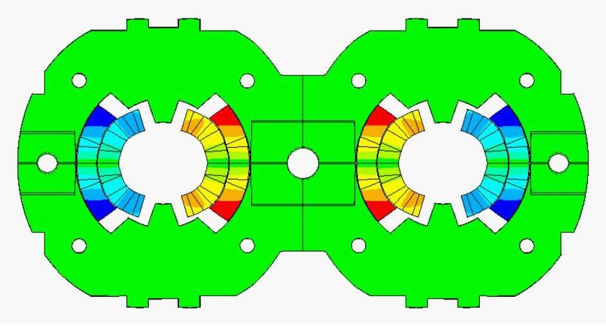
Collars: LHC dipole
 • Two-in-one configuration
 • Both beam pipes are contained
 within one cold mass
 • Stainless steel collars are locked
 by three full-length rods.
 • Magnetic insert
 • It transfers vertical force from the
 yoke to the collared coils
 • It improves field quality
 • Iron yoke vertically split
 • At the end of the welding
 operation the yoke gap is closed MJB Plus, Inc., [1]

 • Stainless steel shell halves are
 welded around the yoke to provide
 He containment, a 9 mm sagitta,
 and to increase rigidity.

 27
Collars: MBH 11 T dipole in HL-LHC
 • Two-in-one configuration
 • Both beam pipes are contained
 within one cold mass
 • Stainless steel collars are locked
 by keys. Pole in titanium, not
 integrated in the collar.
 • Each aperture individually
 collared.
 • Iron yoke vertically split
 • At the end of the welding
 operation the yoke gap is not fully
 closed
 • Stainless steel shell halves are
 welded around the yoke to provide
 He containment, no sagitta, and
 to increase rigidity.

 M. Karppinen, F. Savary, et al
 28
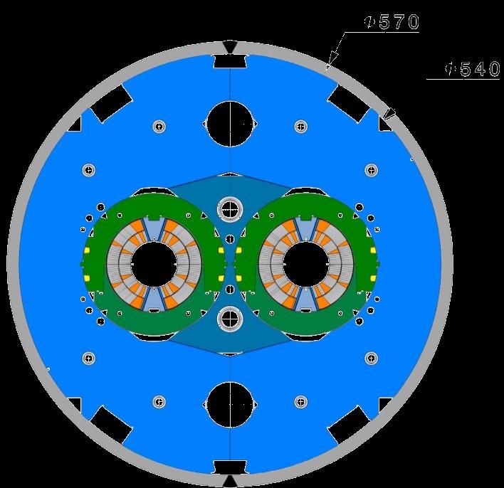
Collars: D2 in HL-LHC
• Each aperture is individually
 collared
 • a pressure is applied to align
 the holes, the keys are
 inserted, the pressure is
 released
• Once collared, the aperture are
 inserted inside the aluminium
 sleeves
 Short model Prototype
• Then a pressure is applied to the
 yokes to close the 1.2 mm gap,
 the C-clamps are inserted, the
 pressure is released
 P. Fabbricatore, S. Farinon, et al
 29
Iron yoke: RHIC dipole
 • The coil is surrounded by glass-
 filled phenolic insulators that
 provide the alignment, insulation
 to ground and separation of the
 coils from the iron to reduce
 saturation effects.

 • The iron yoke clamps the coil-
 insulator structure like a collar.

 • Stainless steel shell halves are
 welded around the yoke to MJB Plus, Inc., [1]

 provide He containment, a 48.5
 mm sagitta, and to increase
 rigidity.

 30
Iron yoke: D1 in-HL LHC
 • 4-way split stainless steel collars

 • The iron yoke clamps the coil-collar
 structure, applying a target pre-
 stress of 115 MPa at warm. About
 half of the pre-stress is lost during
 cool down.

 • Iron very close to the coil, providing
 an important 3D contribution to first Iron collars for D1 in HL-LHC
 order harmonics even for a 7 m (T .Nakamoto, M. Sugano, et al.)
 length magnet.

 31
Aluminum shell-based support structures
 LBNL development on dipole configuration

 LARP development on quadrupole configuration

 RD, HD and LARP magnets (G. Sabbi, P. Ferracin, G. Ambrosio, S. Caspi, et many al.)

 32
Al shell: MQXF in HL-LHC • Aluminum shell, bladder and key technology, prima for accelerators • During cool-down increase in coil/shell stress • Predictable stress variation Capability to control final coil and shell stress MQXFS4 MQXFS6 33
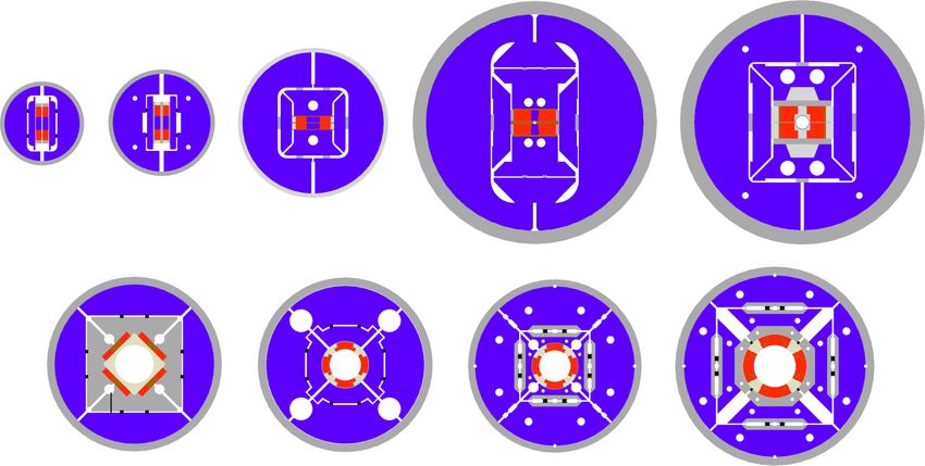
Other structures for stress management
 • The structure gives a dilution of the current density, i.e. a less effective design.
 • But this is a price we are ready to pay to reach higher fields

 • Canted cos theta
 • Each turn is individually supported
 • The stress is managed also radially since there is a segmentation in several
 layers, each one supported
 • No mechanism to provide azimuthal prestress

 S. Caspi, et al. IEEE TAS 27 (2017) 4001505 B. Auchman, et al., . IEEE TAS 28 (2018) 4002805

 34
Other structures for stress management
• The structure gives a dilution of the current density, i.e. a less effective design.
 • But this is a price we are ready to pay to reach higher fields

• Cos theta with stress management
 • keep the traditional shell-type structure with the floating wedges and pole blocks
 for the inner coil (layers 1and 2);
 • maximally unload the inner coil by redistributing turns between the inner and the
 outer coil;
 • introduce the azimuthal and radial SM in the outer coil (layers 3 and 4) only.

 I. Novitski, A. Zlobin, FNAL-CONF-17-340 (2017)

 35
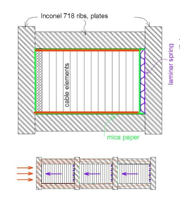
Other structures for stress management
 • For block coils, proposal by Texas A&M
 • Each coil block is isolated in its own compartment and supported separately.
 • E.m. force exerted on multiple coil blocks does not accumulate, but it is
 transmitted to the magnet frame by the Inconel ribs to Inconel plates.
 • A laminar spring is used to preload each block
 • Main difficulty is to have both stress interception and preload
 • Several years of research, concept not yet proved

 P. Mcintyre, IEEE TAS between 1995 and today

 36
Axial support
 • ‘Two schools’ in terms of longitudinal support, with no consensus
 on the magnet community:

 • Limit the coil displacements due to electromagnetic forces by having
 a rigid structure in the longitudinal direction (LHC Dipole, MBH-11 T
 concept, end-plate welded to the shell)

 • Limit the coil displacements due to electromagnetic forces by having
 a rigid structure in the longitudinal direction and pre-load coil ends to
 compensate the axial forces and keep coil end turns under
 compression (MQXF, FRESCA2, concept, )

 37
Axial support: force or not force?
• Two type of axial displacements:
 • Relative movement of the coil with respect to the structure. It depends on
 the overall stiffness of the structure, i.e., independent of the level of pre-
 load in the ends.
 • Relative movement of the coil ends with respect to the pole. It depends of
 the level of pre-load.

 • This was extensively
 studied in LBNL,
 developing the rods -
 plate axial pre-load
 system we are currently
 using for MQXF

 S. Caspi, P. Ferracin., “Towards integrated design
 and modeling of high field accelerator magnets,”
 IEEE Trans. Appl. Supercond., vol. 16, no. 2, pp.
 1298–1303, June 2006.

 38
 Axial displacements of inner layer’s (0.2 friction factor assumed).
 Limited axial support (top) and full axial support (bottom).
Axial support: welded end plate
• We take as example the 11 T dipole for the HL-LHC
• Slight pre-load at room temperature, to guarantee that
 there is still contact coil to end plate at 1.9 K.
• Goal: limit the coil displacements providing a rigid
 lateral support
• 1in1 models:
 • 43 mm thick end-plate, 12 mm stainless steel shell.
• 2in1 models:
 • 75 mm thick end-plate, 15 mm stainless steel shell.

 39
Axial support: rods and end-plate
• We take as example the MQXF quadrupole for the
 HL-LHC

• Direct connection between the motion of the rod
 and the one of the coil ends
 • Very nice and clean measurements!

• Goal: keep the pole turn under compression during
 powering.

• Short models (1.2 m):
 • Aluminum rods, 36 mm diameter
 • Nitronic 50 end plate, 75 mm thick

• MQXFA (4.2 m):
 • Stainless steel rods, 32 mm diameter Measured delta in the rods during powering from 0 to I nom
 • Nitronic 50 end plate, 75 mm thick
 Rod Rod Rod
 Force % of Fem
 Strain Stress elongation
• MQXFB (7.15 m): [MN] at Inom
 [µɛ] [MPa] [mm]
 • Stainless steel rods, 35 mm diameter
 MQXFS 75 6 0.02 2 0.12
 • Nitronic 50 end plate, 75 mm thick
 MQXFA 80 13 0.05 4 0.37
 MQXFB 80 16 0.06 5 0.60
 40
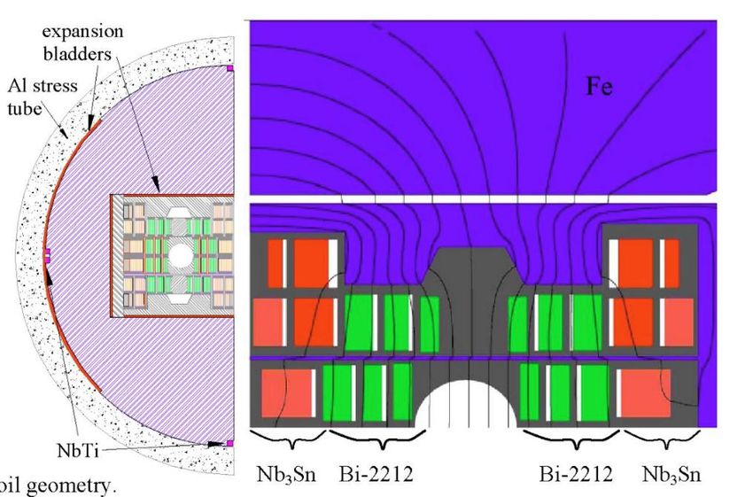
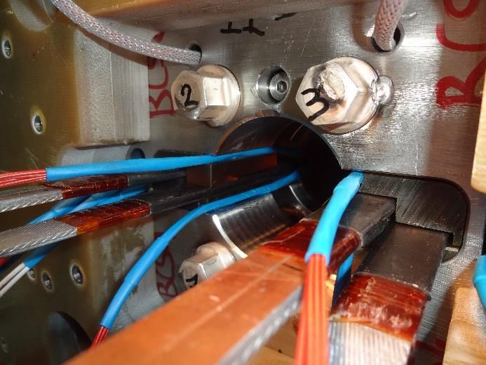
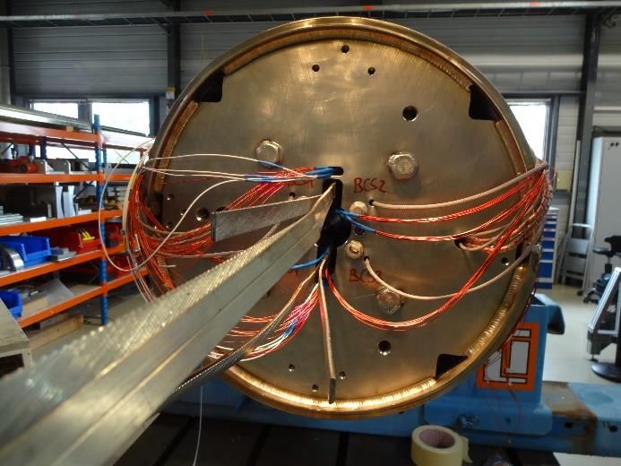
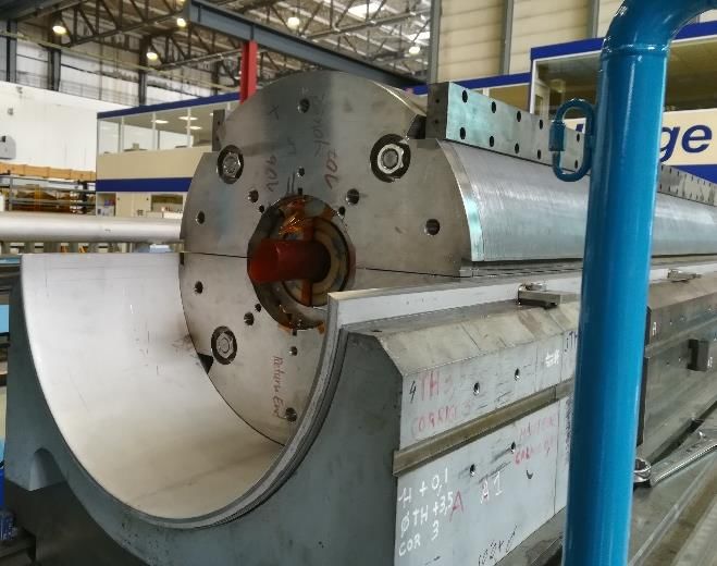
More examples of rods and end-plate
 FRESCA2 eRMC/RMM
 Shell

 Yoke

 Top pad

 Pole

 Tie-rod
 Spacers
 Coil ends
 End-shoes
 End-plate

 G. De Rijk, P. Ferracin, et al. S. Izquierdo Bermudez, J. C. Perez, , et al.

 MDPCT1 dipole HD2 dipole

 G. Sabbi, S. Caspi, et al.
 A. Zolbin, I. Novitski et al.
 41
Summary
 • We presented the force profiles in superconducting magnets. In
 dipole and quadrupole magnets, the forces are directed towards
 the mid-plane and outwardly.
 • They tend to separate the coil from the pole and compress
 the mid-plane region
 • Axially they tend to stretch the windings

 • The importance of the coil pre-stress has been pointed out, as a
 technique to minimize the conductor motion during excitation.

 • There are several ways of designing a support structure
 • The solution for a given magnet is not unique

 42
Summary
 • Structures based on collars are the workhorse of Nb-Ti magnets
 • Guarantees adequate support to avoid deformation and allows giving
 azimuthal prestress
 • A partial support of the iron yoke has been used in several
 cases
 • This allows reducing the collar thickness, and having more
 contribution to the field, and reduction of collar deformation
 • A total support of the yoke is also an option
 • Very thin spacers allow to place the iron much closer to the coil,
 reducing the current density, and therefore stress
 • It a very rigid structure due to the large thickness of the iron
 • Aluminum shell structure guarantees that the peak pre-stress is
 reached in operational conditions
 • Introduced in LNBL, used in several Nb3Sn magnets where the
 degradation threat at 150 MPa is present
 • It showed to be suitable to a very precise control of prestress
 • It has been scaled from 1-m-long to 3.4 m long magnets with LARP,
 and to 7.15 m long magnet in HL LHC MQXFB at CERN

 43
References
 • [1] MJB Plus, Inc. “Superconducting Accelerator Magnets”, an
 interactive tutorial.
 • [2] Paolo Ferracin, USPAS - Superconducting Magnets for Particle
 Accelerators, Unit 10, 13 and 14 (available in
 https://indico.cern.ch/event/440690/ )
 • [3] Y. Iwasa, “Case studies in superconducting magnets”, New York,
 Plenum Press, 1994.
 • [4] M. Wilson, “Superconducting magnets”, Oxford UK: Clarendon
 Press, 1983.
 • [5] A.V. Tollestrup, “Superconducting magnet technology for
 accelerators”, Ann. Reo. Nucl. Part. Sci. 1984. 34, 247-84

 44
You can also read