Study on Surrounding Rock Stability Mechanism of Gob-Side Entry Retaining with Prefabricated Fracture
←
→
Page content transcription
If your browser does not render page correctly, please read the page content below
Hindawi
Advances in Civil Engineering
Volume 2021, Article ID 5819672, 7 pages
https://doi.org/10.1155/2021/5819672

Research Article
Study on Surrounding Rock Stability Mechanism of Gob-Side
Entry Retaining with Prefabricated Fracture

 Hao Wu , Chuanqu Zhu , and Qingfeng Li
 School of Resource and Environment and Safety Engineering, Hunan University of Science and Technology, Xiangtan,
 Hunan 411201, China

 Correspondence should be addressed to Hao Wu; 1457121507@qq.com

 Received 19 June 2021; Revised 21 July 2021; Accepted 4 August 2021; Published 12 August 2021

 Academic Editor: Qibin Lin

 Copyright © 2021 Hao Wu et al. This is an open access article distributed under the Creative Commons Attribution License, which
 permits unrestricted use, distribution, and reproduction in any medium, provided the original work is properly cited.
 To study the optimal layout of prefabricated roof cutting line in gob-side entry retaining with roof cutting and pressure relief,
 based on the engineering geological conditions of 5249 working face in Beipingdong Coal Mine of Baoyuan Mining Company, the
 FLAC3D numerical simulation method was used to study the surrounding rock characteristics of gob-side entry retaining under
 different layout conditions of prefabricated roof cutting line, and the optimal layout of prefabricated roof cutting line in gob-side
 entry retaining with roof cutting and pressure relief was proposed. The results show that the roadway floor has a certain degree of
 floor heave with the mining process under different angles. The angle between the prefabricated roof cutting line and the vertical
 line of the roadway has little effect on the lateral displacement of the coal body in the mining process of gob-side entry retaining.
 When the cutting angle is 10°, the stability of the surrounding rock of gob-side entry retaining is more stable than that of other
 angles, and the plastic range is small. The stability of the surrounding rock of the roadway is more stable than that of other angles,
 which is conducive to the safe mining of 5249 working faces in Beipingdong Coal Mine.

1. Introduction and roadside support [12–16]. Around these contents, some
 experts and scholars studied the strata behavior law of gob-
In recent years, roof cutting and pressure relief gob-side side entry retaining in fully mechanized top coal caving
entry retaining technology has been widely used in coal [17, 18], analyzed the main parameters and adaptability of
mining. This technology cuts the roof by presplitting blasting gob-side entry retaining [19–21], and according to the
and cuts off the long cantilever beam of the roadway roof, laboratory test results, analyzed two kinds of roof breaking
thereby changing the stress structure of the roof strata and modes of gob-side entry retaining in fully mechanized top
reducing the support resistance. Compared with the tradi- coal caving and their influence on surrounding rock de-
tional coal pillar retaining technology, it effectively improves formation [22, 23]. These research results have certain
the coal recovery rate and stress concentration [1–5]. The key guiding significance for the rational use of gob-side entry
to the success of roof cutting and roadway retaining is to retaining technology in fully mechanized caving. The sur-
design reasonable roof cutting parameters, which is bene- rounding rock affected by mining, including the filling body
ficial with the law of stope ground pressure and the roof is for retaining roadways in the later stage, is an interactive
cut down smoothly. Therefore, study on gob-side entry whole. These surrounding rock bodies interact with each
retaining with roof cutting mainly includes the strata be- other after mining, causing the overall deformation of
havior law and presplitting key parameters of slitting [6–11]. surrounding rock bodies. In this process, the main roof,
 The main research contents involved in gob-side entry direct roof, top coal, filling body, and bottom plate form a
retaining include the law of surrounding rock activity, the bearing structure with self-stability. There are many factors
interaction relationship between surrounding rock and affecting the stability of the structure, such as the location of
support, the support in roadway, reinforcement support, the main roof fracture, the length of the end without top coal
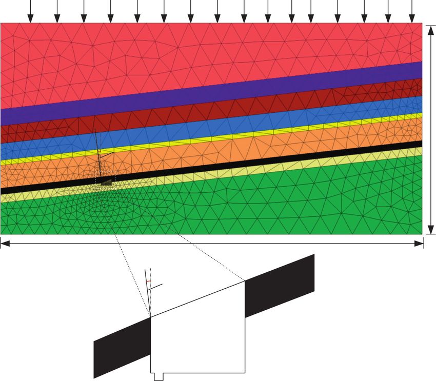
2 Advances in Civil Engineering

caving, the original roadway support technology, the width 3. Establishment of Numerical Model
of the filling body, the filling method, and the strength of the
filling body. It is essential to study the influence law of these According to the field condition characteristics of 5249
factors and the deformation characteristics of roadway working faces in Beipingdong Coal Mine, the FLAC3D
retaining for the rational and effective use of gob-side entry numerical simulation model is established as shown in
retaining technology. Figure 2. The calculation model is 100 m long, 50 m tall, and
 Zheng et al. [24] and Kong et al. [25] used a certain mine 50 m wide, and the average thickness of the coal seam is
as a prototype to carry out similar simulations and industrial 1.1 m. The whole model is divided into 56547 grids and
tests to verify the effectiveness of the strong gang and strong 11325 nodes. The left, right, and lower boundaries are fixed,
angle support technology in the roadway reservation. Chen and the upper boundary is subjected to vertical stress.
[26] used the method of hydraulic fracturing the roof to The buried depth of the coal seam is 600 m, and the
relieve pressure, fracturing the basic roof of the goaf in ad- average density of the rock stratum is 2500 kg/m3. Initial
vance, and minimized the formation of the cantilever beam vertical stress applied at the top of the model P � 15 MPa. To
structure on the basic roof of the adjacent goaf, thereby re- conform the field practice as far as possible, the
ducing and transferring the roof of the roadway along the Mohr–Coulomb strength criterion is adopted in the cal-
goaf. The strength of the supporting pressure solves the culation process [29].
problem that the roadway along the goaf is affected by the ���
 fs � σ 1 − σ 3 + 2c N∅ ,
supporting pressure of the cantilever beam formed by the
unbroken basic roof of the adjacent goaf. Wang et al. [27] 1 + sin φ (1)
studied the crack development mechanism and influencing N∅ � .
 1 − sin φ
factors of the cut-top unloading roadway in the thick coal
seam and proposed dividing the roadway into the advanced In the formula, σ 1 and σ 3 are the minimum and max-
support zone, the dynamic pressure influence zone, and the imum principal stresses, respectively, and C and φ are the
stable zone and the criterion conditions for the development demonstrated cohesion and friction angle, respectively.
of the cracks. Wu et al. [28] analyzed the geometric shape, When fs > 0, the material will undergo shear failure. The
severity, and dynamic evolution process of surrounding rock Mohr–Coulomb model can fully reflect the strength char-
pressure, clarified the asymmetric deformation and failure acteristics of rock. The physical and mechanical properties of
mechanism of surrounding rock along the gob-side roadway rock are shown in Table 1.
in deep wells, and proposed the key technology of grading and
zoning coupling support for the surrounding rock structure. 4. Analysis of Numerical Simulation Results
 The layout of the prefabricated top-cutting line is an
important part of the technology of retaining lanes along the 4.1. Analysis of Surrounding Rock Deformation of Roadway
goaf, but there are few studies on its layout. Therefore, this along Goaf. To study the layout direction of prefabricated
paper uses the FLAC3D simulation software to simulate the roof cutting line in gob-side entry retaining, the models of
engineering geological conditions of the 5249 working face roof cutting line deflection to the roadway roof side, vertical
of the Beipingtong Coal Mine of Baoyuan Mining Company. roadway roof, and deflection to the goaf side are established,
The layout of the prefabricated roof cut-off line affects the respectively. The angle between the tangent line to the goaf
stability of the surrounding rock along the goaf roadway, and side and the vertical line of the roadway roof is positive, and
the optimal layout of the precast roof cut-off line can also the angle to the roadway side is negative. As shown in
provide a reference for similar mines along the goaf roadway Figure 3, a monitoring point is arranged at the roof and floor
work. of the roadway, the filling wall side, and the coal side, and the
 deformation and displacement values of all monitoring
2. Engineering Geology points are recorded every 2 m excavation.
 Figure 4 shows the variation of surrounding rock de-
The 5249 working face of Beipingdong Coal Mine is located in formation of roadway under different layout angles of the
the 4th mining area, which is close to the 5447 working face in cutting line. It can be seen from Figure 4(a) that the roof
the east and the unmining area in the west. The south is close subsidence increases steadily with the mining progress
to 6246 caving area, the north is close to 54 transportation under different roof cutting angles before the mining reaches
downhill, the east working face is 100 m long, and the west 30 m. When the vertical angle between the roof cutting line
working face is 110 m long. The average thickness and dip and the roadway is −5°, the slope is the largest because at this
angle of coal seam in 5449 air roadway of Beipingdong Coal time the roof cutting line is biased towards the roadway side,
Mine are 1.2 m and 29°, respectively. The relative gas emission and the stress concentration occurring in the roadway is the
is 2.69 m3/t, which belongs to the low gas mine. The ground closest under the conditions of 10° and 15°. When the mining
elevation of this working face is from +185 m to +310 m, and is 30–40 m, the slope of the curve is slightly slowed down,
the floor elevation of the coal seam is from −430 m to 374 m. and the slope is the most obvious when the angle of the
The direct roof of No.4 coal seam is sandy mudstone with an tangent top line and the vertical line of the roadway is 10°
average of 5.4 m, and the direct bottom is sandy mudstone compared with other angles. When mining 40–50 m, be-
with an average thickness of 1.73 m. The histogram of the roof cause the model of the entire coal seam mining is completed,
and floor of the coal seam is shown in Figure 1. the roadway roof subsidence curve shows a significant trend
Advances in Civil Engineering 3

 Rock name Histogram Thickness (m) Lithologic description

 20-17.16 Shallow gray-grey quartz fine sandstone, with thin sandy
 Fine
 mudstone band, siliceous cementation, dense hard wavy
 sandstone 7.68 bedding

 Sandy 1.64-8.74 Ash-deep gray sandy mudstone, containing plant
 mudstone 3.95 fossil coal line, and horizontal bedding

 Fine 0-10.12 Light gray-grey quartz fine sandstone, thin-layer silica gel,
 sandstone 4.17 hard wavy oblique bedding

 Sandy 1.3-12.04 Gray - black sandy mudstone, containing fossil plants and Iron
 mudstone 3.96 nodules, sometimes fine sandstones intersected by coal-line

 Fine 0.6-2.1 Gray - white - feldspar quartz sandstone, siliceous
 sandstone 1.4 cementation, dense
 Sandy 3.0-10.80 Dark gray - black sandy mudstone, locally fine sandstone,
 mudstone 5.40 containing plant fossils and iron nodules
 0.8-1.2
 Four coals Block, semi-bright, main coal seam, local single coal seam
 1.1

 Sandy 0.9-3.87 Black sandy mudstone or argillaceous, thin, containing
 mudstone 2.67 fossil plant roots

 Sandy 1.9-18.7 Deep gray sandy mudstone, containing plant fossils
 mudstone 7.4 and iron nodules, thin sandstone

 Figure 1: Comprehensive histogram of mining area 5249.

 50 m

 α

 100 m

 α

 Figure 2: Numerical simulation model.
4 Advances in Civil Engineering

 Table 1: Physical and mechanical properties of rock mass.
Coal seam and Bulk modulus Shear modulus Tensile strength Cohesion Internal friction Density
strata (GPa) (GPa) (MPa) (MPa) angle (°) (kg·m−3)
Sandy mudstone 8.85 5.93 0.1 2.71 32 2600
Four coals 3.8 4.21 4.38 4.21 32 1400
Fine sandstone 2.0 1.3 0.6 1.6 34 2700

 Monitoring point
 Figure 3: Layout of monitoring points.
of larger; after the completion of coal seam mining strata the collapse of the overlying strata in the goaf. The filling wall
reach equilibrium again, the roof subsidence is maximum will be squeezed to the roadway side by the vertical stress of
when the vertical angle of the roof cut line and the roadway is the overlying strata, as shown in Figure 4(c). It can be seen
−5° and the roof subsidence is minimum when the angle is from the figure that when the vertical angles between the
10°. prefabricated roof cutting line and the roadway are −5° and
 From Figure 4(b), it can be seen that the floor of the 5°, the displacement of the roadway filling wall is signifi-
roadway has a certain degree of floor heave with the mining cantly greater than that of other angles. When the angle is
process under different angles. There is a small settlement in 10°, the increase in the displacement curve is relatively flat
the first 10 m of the mining, and then the amount of floor compared with other angles, and the displacement is small in
heave begins to increase rapidly when the excavation is 30 m. all angles simulated after mining.
This is because most of the roof strata are suspended after the The right side of the gob-side entry retaining model is
pressure relief, which leads to the downward transfer of roof the coal body, which is squeezed by the overlying strata
pressure. The stress release of the floor strata into the space due to the influence of dynamic disturbance during the
causes the floor heave. The increased speed is the slowest mining process. As shown in Figure 4(d), the coal side
under the condition of 10°. The increased speed further moves along the X positive direction during the simula-
increases at the last 10 m of the mining and reaches a stable tion mining process. It is known from the figure that the
value. When the angle of the roof cutting line and the vertical movement is relatively small. This is because the large area
line of the roadway is 10°, the floor heave is the best. In of rock above the coal body is a complete rock layer, and
addition, the floor heave of roadway along the goaf is af- there is a certain distance from the cutting top line, so the
fected by the depth of roadway, the nature of surrounding influence of dynamic disturbance on the coal side is small.
rock, roadway size, section size, and other factors. Because When the excavation is 10 m–40 m, the angle of −5° and
the buried depth of 5249 working face and the section size of 10° is close and less than other angles. When the end of the
roadway in Beipingdong Coal Mine of Baoyuan Mining excavation reaches the balance, the movement of all angles
Company have been determined, this paper only studies the is close. It shows that the angle between the prefabricated
influence of prefabricated roof cutting angle on the stability roof cutting line and the vertical roadway has little effect
of surrounding rock of roadway and takes the floor heave of on the lateral movement of coal in the process of gob-side
floor as an important index to measure the stability of entry retaining mining, but the movement of 10° is the
surrounding rock. According to the amount of floor heave smallest.
under different roof cutting angles, floor heave will occur From the above analysis, it can be seen that when the
under various angles. The selection of roof cutting angle with roof cutting angle is 10°, the connection between the roof of
relatively small amount of floor heave is helpful to the the gob-side entry retaining and the roof of the goaf side is
control of surrounding rock stability in the mining process well cut off, and the disturbance of the collapse of the
and is conducive to the normal and safe mining of working overlying strata on the surrounding rock of the roadway is
face. separated. The stability of the surrounding rock of the gob-
 By cutting off the link between the gob-side entry side entry retaining is more stable than that of other angles,
retaining and the roof of the goaf side, the filling wall of the which is conducive to the safe mining of the thin coal seam
roadway bears the force of the whole overlying strata during working face.
Advances in Civil Engineering 5

 80 35

 70
 30
 Roof falling capacity (mm)

 60

 Floor heave (mm)
 25
 50
 20
 40

 15
 30

 20 10

 –5 0 5 10 15 20 25 30 35 40 45 50 55 –5 0 5 10 15 20 25 30 35 40 45 50 55
 Mining length (m) Mining length (m)
 0° 10° 0° 10°
 –5° 15° –5° 15°
 5° 5°
 (a) (b)
 80 Lateral displacement of coal mass (mm) 25
 The displacement of filling body (mm)

 70
 20
 60

 50 15
 40
 10
 30

 20 5
 10
 0
 0
 –5 0 5 10 15 20 25 30 35 40 45 50 55 –5 0 5 10 15 20 25 30 35 40 45 50 55
 Mining length (mm) Mining length (m)
 0° 10° 0° 10°
 –5° 15° –5° 15°
 5° 5°
 (c) (d)

Figure 4: Variation of surrounding rock deformation of roadway: (a) roof subsidence curve; (b) curve of floor heave; (c) displacement of
filling wall; (d) coal body convergence curve.

4.2. Analysis of Plastic Zone of Surrounding Rock of Roadway process. With the increase in mining times, the area of
along Goaf. With the continuous advancement of the plastic zone will be larger and larger. In order to select the
working face, the free space between the caving height range best cutting angle, the maximum plastic zone range under
and the upper stable rock stratum will gradually increase. different cutting angles after the mining of model coal seam
However, the broken rock mass does not bear the vertical is selected for comparison. As shown in Figure 5, the dis-
pressure of the upper rock stratum, and a large area of tribution characteristics of plastic zone of surrounding rock
suspended roof space and a long-term pressure relief space mass structure after gob-side entry retaining mining are
will be formed on the goaf side of the roadway section. At completed under different layout angles of top-cutting line.
this time, the plastic failure of the surrounding rock of the In advance of the gob-side entry retaining working face,
roadway will occur. The analysis of the plastic zone of the the caving rock mass does not bear the vertical stress of the
surrounding rock of the gob-side entry retaining with roof upper rock stratum, which makes the goaf side form a large
cutting and pressure relief is an important basis for selecting area of hanging roof space. Under the pressure of the
a reasonable roof cutting angle. Plastic failure occurs in the overlying rock stratum, there is a large friction and relative
surrounding rock of roadway retained in each mining dislocation between the caving rock mass and the
6 Advances in Civil Engineering

 Zone Zone
 Colorby: State -Average Colorby: State -Average
 None None
 shear-n shear-n
 shear-n shear-p shear-n shear-p
 shear-n shear-p tension-p shear-n shear-p tension-p
 shear-n tension-p shear-n tension-p
 shear-p shear-p
 shear-p tension-p shear-p tension-p
 tension-n tension-n
 tension-n shear-p tension-n shear-p
 tension-n shear-p tension-p tension-n shear-p tension-p
 tension-n tension-p tension-n tension-p
 tension-p tension-p

 (a) (b)
 Zone Zone
 Colorby: State -Average Colorby: State -Average
 None None
 shear-n shear-n
 shear-n shear-p shear-n shear-p
 shear-n shear-p tension-p shear-n shear-p tension-p
 shear-n tension-p shear-n tension-p
 shear-p shear-p
 shear-p tension-p shear-p tension-p
 tension-n tension-n
 tension-n shear-p tension-n shear-p
 tension-n shear-p tension-p tension-n shear-p tension-p
 tension-n tension-p tension-n tension-p
 tension-p tension-p

 (c) (d)
 Zone
 Colorby: State -Average
 None
 shear-n
 shear-n shear-p
 shear-n shear-p tension-p
 shear-n tension-p
 shear-p
 shear-p tension-p
 tension-n
 tension-n shear-p
 tension-n shear-p tension-p
 tension-n tension-p
 tension-p

 (e)

Figure 5: Distribution chart of surrounding rock plasticity under different cutting angles of prefabrication: (a) 0°; (b) −5°; (c) 5°; (d) 10°; (e) 15°.

presplitting interface of the roof. Because the filling wall and the collapse of the overlying strata on the sur-
the whole overlying rock stratum of the roadway roof have a rounding rock of the roadway is separated. The
large range of pure shear plastic zones, tensile failure occurs stability of the surrounding rock of the gob-side
in a certain range of the roadway roof and the overlying rock entry retaining is more stable than that of other
stratum of the goaf. When the angle between the pre- angles, which is conducive to the safe mining of the
fabricated roof cutting line and the roadway roof is 10°, the 5249 working face in Beipingdong Coal Mine.
plastic failure zone of the whole model is the smallest. To
obtain a layout of the prefabricated roof cutting line of the Data Availability
gob-side entry with better surrounding rock control, the
vertical angle between the prefabricated roof cutting line and The data used to support the findings of this study are
the roadway roof should be 10°. available from the corresponding author upon request.

5. Conclusion Conflicts of Interest
 (1) The roadway floor has a certain degree of floor heave The authors declare that they have no conflicts of interest.
 with the mining process under different angles. The
 angle between the prefabricated roof cutting line and References
 the vertical roadway has little effect on the lateral
 displacement of the coal body in the mining process [1] N. Meng, J. Bai, Y. Chen, X. Wang, W. Wu, and B. Wu,
 of gob-side entry retaining. When the roof cutting “Stability analysis of roadside backfill body at gob-side entry
 retaining under combined static and dynamic loading,” En-
 angle is 10°, the deformation of the roadway sur-
 gineering Failure Analysis, vol. 127, Article ID 105531, 2021.
 rounding rock is the best. [2] X. Yu, Z. Sun, M. Deng, and J. Xin, “Grouting technique for
 (2) The large friction and relative dislocation between gob-side entry retaining in deep mines,” Advances in Civil
 the caving rock mass and the presplitting interface of Engineering, vol. 2021, Article ID 5343937, 9 pages, 2021.
 the roof lead to a large range of plastic zones in the [3] Z. Xiao and K. Hongpu, “Pressure relief mechanism of di-
 roof of the roadway and the overlying strata of the rectional hydraulic fracturing for gob-side entry retaining and
 goaf, and the plastic zone is the smallest when the its application,” Shock and Vibration, vol. 2021, Article ID
 angle is 10°. 6690654, 8 pages, 2021.
 [4] T. Qin, K. Ren, C. Jiang, Y. Duan, Z. Liu, and L. Wang,
 (3) When the roof cutting angle is 10°, the connection “Distribution law of mining stress of the gob-side entry
 between the gob-side entry retaining roof and the retaining in deep mining thin coal seam,” Advances in Civil
 gob-side roof is well cut off, and the disturbance of Engineering, vol. 2021, Article ID 5589948, 9 pages, 2021.
Advances in Civil Engineering 7

 [5] Y. Zhang, H. Xu, P. Song, X. Sun, M. He, and Z. Guo, “Stress [19] J. Zhang and Y. Li, “The stability of gob-side entry retaining in
 evolution law of surrounding rock with gob-side entry a high-gas-risk mine,” Advances in Civil Engineering,
 retaining by roof cutting and pressure release in composite vol. 2019, Article ID 7540749, 12 pages, 2019.
 roof,” Advances in Materials Science and Engineering, [20] X. Sun, L. Gan, Z. Chengwei et al., “Numerical investigation of
 vol. 2020, Article ID 1961680, 15 pages, 2020. gob-side entry retaining through precut overhanging hard
 [6] D. Kong, S. Pu, Z. Cheng, G. Wu, and Y. Liu, “Coordinated roof to control rockburst,” Advances in Civil Engineering,
 deformation mechanism of the top coal and filling body of vol. 2018, Article ID 8685427, 10 pages, 2018.
 gob-side entry retaining in a fully mechanized caving face,” [21] H. Luan, Y. Jiang, L. Zhou, and H. Lin, “Stability control and
 International Journal of Geomechanics, vol. 21, no. 4, Article quick retaining technology of gob-side entry: a case study,”
 ID 04021030, 2021. Advances in Civil Engineering, vol. 2018, Article ID 7357320,
 [7] X. Liu, X. Hua, P. Yang, and Z. Huang, “A study of the 13 pages, 2018.
 mechanical structure of the direct roof during the whole [22] H. Yang, S. Cao, S. Wang, Y. Fan, S. Wang, and X. Chen,
 process of non-pillar gob-side entry retaining by roof cutting,” “Adaptation assessment of gob-side entry retaining based on
 Energy Exploration & Exploitation, vol. 38, no. 5, pp. 1706– geological factors,” Engineering Geology, vol. 209, 2016.
 1724, 2020. [23] Y. Xu, J. Chen, and J. Bai, “Control of floor heaves with steel
 [8] Z. Zhang, M. Deng, J. Bai, X. Yu, Q. Wu, and L. Jiang, “Strain pile in gob-side entry retaining,” International Journal of
 energy evolution and conversion under triaxial unloading Mining Science and Technology, vol. 263 pages, 2016.
 [24] F. Zheng, L. Shan-Ren, B. Huang, C. Feng-Ji, and R. Peng,
 confining pressure tests due to gob-side entry retained,” In-
 “Similar model test study on application of Qiang Bang Qiang
 ternational Journal of Rock Mechanics and Mining Sciences,
 Jiao in gob side entry retaining,” Journal of Mining and Safety
 vol. 126, Article ID 104184, 2020.
 Engineering, vol. 38, no. 1, pp. 94–102, 2021.
 [9] Z. Zhang, M. Deng, J. Bai, S. Yan, and X. Yu, “Stability control
 [25] X. Kong, R. Shan, and T. Ju, “Model test study on deformation
 of gob-side entry retained under the gob with close distance
 and failure mechanism of surrounding rock of coal roadway
 coal seams,” International Journal of Mining Science and and its engineering application,” Journal of Mining and Safety
 Technology, vol. 31, no. 2, pp. 321–332, 2021. Engineering, vol. 34, no. 3, pp. 464–471, 2017.
[10] Z. Zhang, J. Bai, Y. Chen, and S. Yan, “An innovative ap- [26] J. Chen, “Research on collaborative control technology of
 proach for gob-side entry retaining in highly gassy fully- surrounding rock pressure relief support for gob side entry
 mechanized longwall top-coal caving,” International Journal retaining,” Coal Science and Technology, vol. 48, no. 8,
 of Rock Mechanics and Mining Sciences, vol. 80, pp. 1–11, 2015. pp. 44–49, 2020.
[11] Z. Zhang, W. Wang, S. Li et al., “An innovative approach for [27] J. Wang, S. Wang, J. Yang, Q. Wang, L. Ma, and M. He, “Roof
 gob-side entry retaining with thick and hard roof: a case failure mechanism and control technology of gob side entry
 study,” Technical Gazette, vol. 25, no. 4, pp. 1028–1036, 2018. retaining by roof cutting and pressure relief,” Coal Science and
[12] X. Sun, Y. Liu, J. Wang, J. Li, S. Sun, and X. Cui, “Study on Technology, vol. 45, no. 8, pp. 80–84, 2017.
 three-dimensional stress field of gob-side entry retaining by [28] J. Wu, J. Kan, S. Xie, F. Xie, and Y. Zhao, “Research on
 roof cutting without pillar under near-group coal seam asymmetric failure mechanism and control technology of gob
 mining,” Processes, vol. 7, no. 9, 552 pages, 2019. side entry retaining in deep mine,” Journal of Mining and
[13] C. Han, N. Zhang, J. Xue, J. Kan, and Y. Zhao, “Multiple and Safety Engineering, vol. 34, no. 4, pp. 739–747, 2017.
 long-term disturbance of gob-side entry retaining by grouped [29] M. Qian, X. Miao, J. Xu, and X. Mao, Key Strata Theory of
 roof collapse and an innovative adaptive technology,” Rock Strata Control, China University of Mining and Technology
 Mechanics and Rock Engineering, vol. 52, no. 8, pp. 2761–2773, Press, Beijing, China, 2003.
 2019.
[14] X. Liu, D. Fan, Y. Tan et al., “Failure evolution and instability
 mechanism of surrounding rock for close-distance parallel
 chambers with super-large section in deep coal mines,” In-
 ternational Journal of Geomechanics, vol. 21, no. 5, Article ID
 04021049, 2021.
[15] X. Liu, S. Song, Y. Tan et al., “Similar simulation study on the
 deformation and failure of surrounding rock of a large section
 chamber group under dynamic loading,” International
 Journal of Mining Science and Technology, vol. 31, no. 3,
 pp. 495–505, 2021.
[16] X. Liu, D. Fan, Y. Tan et al., “New detecting method on the
 connecting fractured zone above the coal face and a case
 study,” Rock Mechanics and Rock Engineering, vol. 54, no. 8,
 pp. 4379–4391, 2021.
[17] P. Gong, Z. Ma, J. Sun, and R. R. Zhang, “The blocking
 mechanism of the vertical feeding system of roadside support
 body material for backfilling gob-side entry retaining,” Ad-
 vances in Civil Engineering, vol. 2019, Article ID 6060197,
 13 pages, 2019.
[18] S. Xiao-ming, L. Gan, S. Peng et al., “Application research on
 gob-side entry retaining methods in no. 1200 working face in
 Zhongxing mine,” Geotechnical and Geological Engineering,
 vol. 37, no. 1, pp. 185–200, 2019.
You can also read