Miniature HCCI Free-Piston Engine Compressor
←
→
Page content transcription
If your browser does not render page correctly, please read the page content below
2009-32-0176/20097176

                             Miniature HCCI Free-Piston Engine Compressor

                                                                              For Orthosis Application
                                                                    Lei Tian, David B. Kittelson, William K. Durfee
                                                                       Mechanical Engineering, University of Minnesota, USA

Copyright © 2009 SAE Japan and Copyright © 2009 SAE International

ABSTRACT                                                               compressor and pneumatic actuator are used for the
                                                                       power source of an AFO, an overall system efficiency
A miniature homogenous charge compression ignition                     of only 1.1% is needed to realize a higher power
(HCCI) free-piston engine compressor aimed at an                       density than battery-motor package [3]. The proposed
ankle-foot orthosis application is described. Analysis of              active AFO contains a free-piston engine compressor,
the human ankle shows that a fluid power source in the                 an accumulator and pneumatic actuator. This
neighborhood of 10 W is needed. To account for                         illustrates new fluid power opportunities in medical and
compressor and actuator inefficiencies, the power                      assisting devices.
output at the engine cylinder is designed to be 30 W.
                                                                         Free-piston engine
A compact engine compressor package has been                             compressor
designed and mathematically modeled. Experiments
using existing engine components characterized the
leakage model. Through the dynamic simulation of the
engine, major parameters of the engine have been
                                                                             Accumulator
specified. Simulations indicate that the HCCI free-
piston engine compressor, designed in a prototype                                                           Rotary actuator
package scale of about 80x40x20 mm is a viable
compact and efficient fluid power supply. Simulation
results demonstrate that the overall efficiency of the
engine compressor is expected to be 5.9% and that the
package should have a higher energy density than
batteries.                                                             Fig. 1 CCEFP Ankle Foot Orthosis. Image from
                                                                       CCEFP.
INTRODUCTION
                                                                       As the scale of an engine gets smaller, surface effects
The Center for Compact and Efficient Fluid Power                       such as friction, heat loss and leakage dominate [3]. In
(CCEFP), a seven university research consortium                        order to mitigate these losses, a free-piston engine
headquartered at the University of Minnesota,                          compressor configuration was chosen, with the engine
Minneapolis USA, is developing a compact, untethered                   running at high speed to mitigate leakage losses.
ankle foot orthosis (AFO) as a test bed for new                        Combustion in small spaces is complex with ignition
technologies in tiny fluid power (Figure 1) [1]. Analysis              quenching and leakage problems [5].              HCCI
of the human ankle during normal walking shows that                    combustion is proposed to address those problems.
to completely replace the function of the normal ankle                 Chemical kinetics analysis was conducted for the
with an active AFO, a peak torque of 75 Nm and                         engine, and an ignition model was constructed.
average power of 10 W are required. Each step
requires 14 J are needed for each gait cycle of the                    DESIGN OF THE ENGINE
ankle which means about 70 kJ per day for one side
for a 10,000 step day [2]. Assuming a 50% mechanical                   FREE-PISTON ENGINE – A free-piston engine is a
efficiency from the output of the power supply to ankle                type of internal combustion (IC) engine that has no
power, the power supply needs to produce about 140                     crankshaft. Without the kinematic constraint of a
kJ per day. A Battery and electric motor solution for the              crankshaft, the movement of the piston is dynamically
untethered power source was rejected due to low                        driven by pressures in the combustion, rebound and
power density of batteries (~290 kJ/kg) and the size of                compressor chambers. A rebound device, such as a
a battery-motor package [3].                                           gas spring, metal spring or hydraulic accumulator, is
                                                                       used to store energy for combustion chamber gas
Hydrocarbon fuel has a power density of about 40,000                   compression, and two-cycle combustion is used.
kJ/kg. If an internal combustion engine coupled with
SETC2009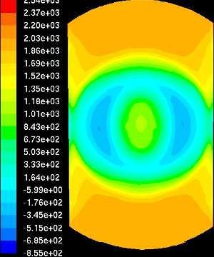
Compared to a crankshaft IC engine, the free-piston OPERATION RANGE FOR MINIATURE HCCI
configuration is more compact and simpler, having ENGINE
fewer moving parts, and no side-thrust between piston
and cylinder wall. Large free-piston engine air The miniature HCCI engine is not simply a scaled
compressor had been developed, such those by down full-scale engine. There are unique features
Pescara [6], Junker [7], and Braun [8]. The biggest which restrict the operation range for the engine. In this
challenge for free-piston engine is that the two-stroke section, overall parameters such as cylinder bore and
cycle requires efficient scavenging but the piston speed are specified.
motion is undefined [9].
PERFORMANCE ESTIMATION – Performance
More recently, attention has been paid to developing estimation following the approach used by Aichlmayr [5]
small free-piston engines. Riofrio et al at Vanderbilt was used to find the major engine parameters. In this
University designed and prototyped a free liquid-piston estimation, several rough approximations were made,
engine compressor in the power range of 100 W [3]. including the scavenging efficiencies model in Taylor et
Aerodyne Research Inc. designed and manufactured al [11]
10 W and 500 W miniature engine-generators, which
are two-stroke free-piston engines coupled to linear
alternators [10]. Their test showed 16% thermal r −1 1 + Λ − e− Λ
efficiency. Aichlmayr et al proposed miniature free-
Λ= ηch =
2r 2
piston engine coupled with Homogenous Charge
Compression Ignition (HCCI) combustion, and
experimentally demonstrated that HCCI can occur in a where Λ is delivery ratio, r is the compression ratio
3 mm bore, circumventing the flame quenching and charging efficiency η ch is the arithmetic mean of
problem in small space [5]. the completely displacement and completely mixing
charging efficiencies. The engine power can be
HCCI COMBUSTION – The proposed engine determined by
proposed here incorporates HCCI combustion, for
several reasons. First, in tiny dimensions, spark plugs 1 2
or a fuel injector are problematic because of their size π ( r − 1)Vt 3
3
and timing is challenging without a crankshaft. Second, PBR = ρ i SN FS Φecη fc ,iη mηch
the -piston engine is suited to HCCI since there is no 4 rR
crankshaft and the compression ratio can adapt to the
onset of HCCI combustion. Third, as the engine
dimension goes down, the flame is more likely to
where PBR is the power of the engine, ρ i is the inlet air
quench due to higher surface area to volume ratio. density, S is the stroke, N is the engine speed (Hz),
HCCI circumvents this problem [5]. Vt is the volume of cylinder, R is the stroke to bore
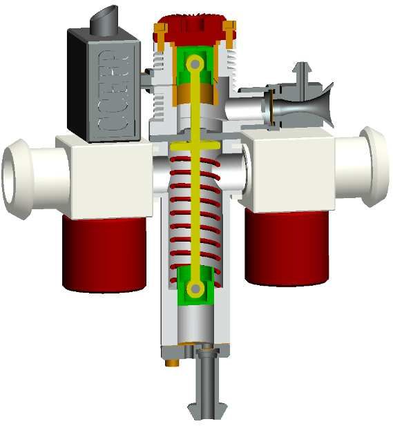
ENGINE DESIGN CONCEPT – The design concept for aspect ratio, FS is the stoichiometric fuel air ratio, Φ is
the new engine is shown in Figure 2 and uses HCCI
the equivalence ratio, ec is the lower heating value of
combustion and a metal spring for rebounding the
piston. the fuel, η fc ,i is the indicated fuel conversion efficiency
Engine piston and ηm is the mechanical efficiency. Using this
equation, Figure 3 shows the relation between speed,
Silencer Carburetor compression ratio and cylinder bore and demonstrates
that the engine should be chosen to be big and slow, or
small and fast.
Starting valves
Bore (mm)
Rebound Compressor piston
spring
Compressed air output
Speed (Hz)
Comp ratio
Fig. 2 Design concept for miniature HCCI free-piston
engine. Fig.3 Relation between speed, compression ratio
and cylinder bore, when aspect ratio = 1.
SETC2009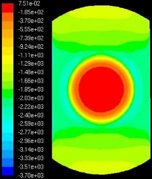
LEAKAGE SIMULATION – As the engine gets smaller
the charge leakage through the cylinder-piston gap
becomes the dominant factor affecting the efficiency of
the engine [12]. This is because the leakage gap stays
the same so that with smaller engines, a higher
percentage of the mass is leaked.

Simulation Approach – An analytical solution can be
derived to solve the gap flow using the Navier-Stokes
equation [12,13]. Sher et al. [12] found that with a
mechanically attainable gap width of 20 um, an engine
of displacement smaller than 0.2 cc, cannot run at
30000 rpm. However, the COX .010 model airplane
engine can run at this speed. This is because the Sher
model neglects the sealing effect of the lubricating oil     Fig. 5 Actual versus geometric compression ratio for
inside the cylinder gap that reduces the leakage. We         several engine speeds
improved Sher’s model by including a parameter that
models this effect.                                          CHEMICAL KINETICS SIMULATION

Experimental Validation – The leakage model was              Approach - HCCI is a different combustion mode
validated by comparing the compression stroke                because the onset of combustion is determined solely
pressure trajectory of the simulation with the pressure      by chemical kinetics during the compression process
recorded in an experiment. An AP Hornet .09 engine           instead of being triggered by a spark as in a SI
was used with a 12.5 mm bore and aluminum piston             gasoline engine or by high pressure fuel injection as in
and brass and chrome coated cylinder liner, the current      a diesel engine. The compression process must be
state-of-the art in small engine machining technology.       simulated properly to determine the operation
After a running in period, the model engine was              characteristics of the HCCI engine.
motored at constant speed of 4900 rpm, and an
Optrand D22255-Q pressure sensor was used to                 The simulation package CHEMKIN is capable of
measure the cylinder pressure. Lubricant oil is added        simulating the chemical kinetics during engine
before motoring to simulate the lubricated running           compression based on chemical kinetics. The heptane
situation of the engines.                                    mechanism developed by Lawrence Livermore
                                                             National Laboratory was used.

                                                             Results - The Chemkin simulation showed that the
                                                             required compression ratio to ignite the fuel increases
                                                             with the engine speed. This can be understood from
                                                             the ignition delay theory for HCCI combustion. As the
                                                             engine speed increases, the ignition delay must be
                                                             decreased to onset the HCCI combustion, thus a
                                                             higher compression ratio is needed.

                                                             For different hydrocarbon fuels, the higher the number
                                                             of carbon atoms in the molecule, the easier the fuel is
                                                             to ignite through compression. Because the reaction
                                                             mechanism for complex mixed fuels such as kerosene
                                                             is not readily available and therefore cannot be
                                                             simulated, the ignition curve for kerosene based model
                                                             diesel fuel was based on experimental observations of
Fig. 4   Experimental validation of leakage model.           model engines operating using this fuel.

This experimental result shown in Figure 4
demonstrates that the leakage inside the cylinder is
exaggerated at high pressure, and under-estimated at
low pressure. This is partially cause by the fact that the
actual engine cylinder is tapered, which means the gap
is larger around BDC. The simulation model will need
to be further improved to model this effect.

Simulation results - The simulation results shown in
Figure 5 reveals that the engine should be run at high
speed to minimize the effect of leakage. While the
geometric compression ratio is limited by engine
geometry the actual compression ratio depends on the
engine speed with the ratio increasing with speed
because of the reduced leakage as speed increases.
SETC2009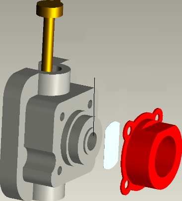
Fig. 6 Ignition curves for various rules showing the          Fig. 8   Operating range for model diesel fuel.
compression ratio required to ignite as a function of
engine speed.                                                 Based on the curve of model diesel fuel shown in
                                                              Figure 6, the operating range of model diesel fuel for a
Fuel for Miniature HCCI Engine - The viable engine            miniature HCCI engine is shown in Figure 8. Viable
operating speeds for different fuels can be determined        operating speeds using this fuel range from about
from the data shown in Figures 5 and 6. While higher          10,000 to about 40,000 rpm.
speed is needed for reducing leakage, the higher
speed makes it harder to ignite the fuel in HCCI mode.        DETERMINATION OF ENGINE SPEED
Figure 7 combines the data for n-heptane from Figures
5 and 6 and shows the fuel retention efficiency, which        Although the previous section demonstrates that the
is the percentage of fuel not leaked out from the             engine should operate over a range of speeds using a
combustion chamber before combustion. When                    kerosene based fuel, additional simulations are needed
operating on n-heptane fuel, the engine only ignites at       to specify a rated nominal operating point at a specific
8000-18000 rpm, while efficiency is negative due to           speed.
severe leakage. At low speeds the leakage is too high
and at high speed the required compression ratio is too       REED VALVE RESPONSE - Because the free-piston
high.                                                         engine lacks a rotating crank shaft, the rotary valves
                                                              commonly used in two-stroke engines cannot be used.
                                                              Instead a reed valve was chosen to trap the fuel air
                                                              mixture inside the crankcase chamber. The reed valve
                                                              designed here is essentially the same as the valve
                                                              used in COX reed valve model engines, which is a
                                                              check valve working on a pressure difference (Figure
                                                              9). The valve needs time to open and close and its
                                                              response is also affected by vibration. At higher
                                                              speeds, the reed lags when opening and closing and
                                                              reduces what otherwise would be an increase in power
                                                              with speed.

                                                                                          Intake channel

                                                                                             Reed
Fig. 7   Operating range for n-heptane fuel.                                                        Reed retainer

This leads to the conclusion that an easily ignitable fuel
must be used for the miniature HCCI engine so that
the speed can be high enough to minimize leakage but
the fuel can still ignite. Our engine will use model diesel
engine fuel, the fuel commonly used for two-stroke
model airplane diesel engines, which are basically
HCCI engines. This fuel is based on kerosene, a large
molecule hydrocarbon mixture that is easy to ignite.          Fig. 9   Reed valve used in COX model engine
The fuel has two percent additive of ignition improver
amyl nitrate to further facilitate ignition.                  The valve vibration was simulated as a cantilever
                                                              beam with an equivalent spring-mass-damper system
                                                              [14]. For simplicity only the first vibration mode was
                                                              considered.

                                                              Pressure Model for Reed Valves - A model for
                                                              pressure on the reed must be employed to determine
                                                              the load on the reed valve due to pressure differences.
                                                              For example, Blair et al. assume linearly changing
                                                              pressure from inlet tract pressure to crankcase
                                                              pressure [15] and Fleck et al. assume linear
                                                              relationship fitted with a reed-lift associated pressure
                                                              reduction factor [16]. In our simulation, the FLUENT
                                                              computational fluid dynamics software was used to
                                                              simulate the pressure distribution on the reed valve
                                                              and a model that relates pressure distribution on reed
                                                              surfaces to reed lift was constructed for a one-
                                                              dimensional simulation. During the inflow to the
                                                              crankcase, the pressure force is

SETC2009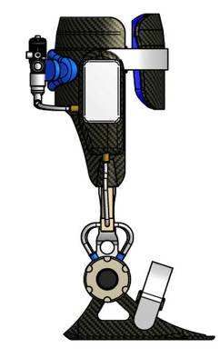
Fp = (0.332 x + 0.213) Areed ∆P
and during the backflow from the crankcase the
pressure is
Fp = − (0.899 x + 0.2134) Areed ∆P
where ∆P is pressure difference in Pa, Areed is reed
surface area, and x is the reed lift in mm. Part of
simulation results are shown in Figure 10.
Fig.12 Engine performance with speed.
ONE DIMENSIONAL DYNAMIC SIMULATION
Once parameters such as the target speed and engine
dimensions are specified, a one dimensional dynamic
model can be constructed to simulate the performance
of the entire engine.
CHEMICAL KINETICS FOR ONE DIMENSIONAL
Fig. 10 CFD results on the pressure distribution on the MODEL – The CHEMKIN simulation is too detailed for
inlet side faces of reed for a 0.32 mm valve lift. The left the one dimensional simulation. Thus a model adapted
image shows the inflow to the crankcase and the right from that of Gregory et al. [17] was used for one-
shows the backflow from the crankcase. dimensional simulation of the miniature HCCI engine.
The free-piston engine does not have a crankshaft
Results - This simulation results shown in Figure 11 angle so instead a time-base integral was used to
reveal that the engine power density, indicated as determine the onset of HCCI combustion as shown by
Delivery ratio * rpm, actually decreases with speeds
exp(C2 / T ) [ fuel ] [O2 ] dt > RRth
higher than 40000 rpm. t
∫ CT
n a b
0 1
where T is the combustion chamber temperature, C1 ,
C2 , a , b are coefficients, and RRth is the threshold
value for onset of combustion. The coefficients and
threshold values were fitted to the CHEMKIN
simulation results of Figure 6 to match the simplified
model to the detailed chemical kinetics. After ignition,
the combustion process is modeled by a Vibe function
t − to m +1
x = 1 − exp − a
∆t
Fig. 11 Reed valve response simulation results.
ENGINE PERFORMANCE WITH SPEED – Combining where x is fuel consumption percentage, to is ignition
the simulation results from the previous sections, the time, ∆t is combustion duration and a and m are
engine power density and efficiency can be related to coefficients for the Vibe function.
engine speed taking into account leakage, chemical
kinetics and reed valve dynamics with speed. The THERMODYNAMIC MODEL FOR EACH CHAMBER –
results are shown in Figure 12. The energy balance of combustion, crankcase and
compressor chambers are determined by the first law
The simulation shows that the optimal speed is of thermodynamics
between 20,000 and 40,000 rpm. Because the higher
speed results in much higher audible noise, 20,000
dT . . .
rpm was specified as the target speed for the engine. mc .v cv = Q − W + ∑ min ( hin − uc .v . )
This speed corresponds to an engine bore of about 7 dt
mm. .
− ∑ m out ( hout − uc.v . )
SETC2009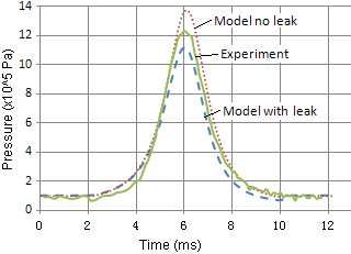
. .
where m is the mass, Q is heat transfer and W is
work transfer. The sub-scripts in and out mean flow in
and out of the control volume.
HEAT TRANSFER MODEL – The heat transfer in the
combustion chamber was calculated using the
methods of Annand et al. [18]. The heat transfer
equations are
~
~
a K ρU p B
b
~
h=
Fig. 14 Piston dynamics model in Simulink.
B µ
DYNAMIC SIMULATION RESULTS
( )
. ~ ~
Q = − Acc h(Tcc − Twall ) − c σ T − T 4
cc
4
wall
CHOOSING PARAMETERS - The Simulink simulation
was then used to select remaining engine design
~ parameters such as the rebound spring constant and
where h is the convection heat transfer coefficient, the compressor dimensions. The procedures to specify
U p is piston speed, K is conductivity, µ is viscosity, the major parameters are first to chose a rebound
spring constant so that HCCI combustion will readily
σ is the Boltzmann constant, Acc is the heat transfer occur from the rebound energy of the spring. Next a
~ ~ ~ piston mass is specified to match the target speed
area, and a , b , c are coefficients. because the rebound spring constant and the spring
mass are two of the major factors that determine the
FREE PISTON DYNAMICS – The free-piston shown in engine speed. A compressor piston size is chosen so
Figure 2 is subject to inertia dynamics defined by that the energy of fuel combustion is partially absorbed
by the compressor and the piston ends up in a position
that scavenging can occur and with sufficient stored
d 2 x piston
m piston = ( Pcc − Pc ) Aengine − Pcomp Acomp − Fspring energy in the rebound spring to drive compression for
the next cycle.
dt 2
Based on those procedures, a spring constant of 1800
N/m and a piston mass of 5 gm are calculated for 300
where Pcc , Pc and Pcomp are combustion chamber, Hz (18,000 rpm) operation. A 5 gm piston is possible if
crankcase and compressor chamber pressures, it is fabricated from aluminum as a typical piston in a
x piston is the piston position, and Fspring is the force model airplane engine weighs 1.3 gms.
exerted by the rebound spring.
ONE DIMENSION MODEL OF THE ENGINE – All the
models discussed in this paper were put into a Matlab
Simulink application to simulate the overall engine
dynamics (Figures 13-14).
Fig. 15 Simulated pressure trace of one cycle at 300
Hz operation simulation.
SIMULATED EFFICIENCIES
Fig. 13 Simulink model for the entire engine.
Engine Indicated Efficiency - The engine indicated
efficiency is the work done on the engine divided by the
energy contained in the fuel flowing into the engine. By
SETC2009this definition, the indicated efficiency was estimated to 6. R.P. Pescara, “Motor Compressor Apparatus”,
be 24.4%. 1928, U.S. Patent 1,657,641
7. K. Neumann, “Junkers free-piston compressor”,
Overall Efficiency – Using an analysis similar to Barth 1935, American Society of Mechanical Engineers,
et al [19] and taking into account that the compressed Volume 57 issue 4
air will eventually cool to ambient temperature and lose 8. A.T. Braun, Paul H. Schweitzer, “Braun Linear
some of its energy, the energy stored in compressed Engine”, 1973, SAE Preprint 730185
air is 9. R. Mikalsen, A.P. Roskilly, “A review of free-piston
engine history and applications”, 2007, Applied
Pcomp − Patm Thermal Engineering, Volume 27 issue 14-15
Energy _ stored = mair RTatm 10. Kurt D. Annen, David B. Stickler, Jim Woodroffe,
Pcomp “Glow Plug-Assisted HCCI Combustion in a
Miniature Internal Combustion Engine Generator”,
th
where subscripts comp and atm denote compressed 2006, 44 AIAA Aerospace Science Meeting
air and atmosphere. Based on this equation, the 11. C. F. Taylor. “The Internal Combustion Engine in
overall efficiency of the engine compressor is defined Theory and Practice: Volume I: Thermo-dynamics,
as the energy stored in the cooled compressed air, Fluid Flow, Performance”, 1985, The M.I.T. Press,
divided by the energy of the fuel that flowed into the Cambridge, MA
engine to create the compressed air. By this definition, 12. I. Sher, D. Levinzon-Sher, E. Sher, “Miniaturization
the simulation showed that the overall efficiency would
Limitations of HCCI Internal Combustion Engines”,
be 5.9%.
2009, Applied Thermal Engineering, volume 29
13. S.K. Grinnel, “Flow of a Compressible Fluid in a
CONCLUSION Thin Passage”, 1955, American Society of
Mechanical Engineers
A compact HCCI free-piston engine compressor was
14. E. T. Hinds and G. P. Blair, "Unsteady Gas Flow
conceived, designed and modeled. The operation
Through Reed Valve Induction Systems," 1978,
range for miniature HCCI engine was analyzed and a
SAE Paper
target speed of about 20,000 rpm was specified.
Experimental measurements were used to calibrate 15. G. P. Blair and E. T. Hinds, "Predicting the
and validate the leakage model. Dynamic simulation Performance Characteristics of Two-Cycle Engines
shows the potential overall efficiency of the engine- Fitted with Reed Induction Valves," 1979, SAE
compressor to be 5.9%, which would be a higher Paper
power density than batteries. 16. R. Fleck, A. Cartwright and D. Thornhill,
"Mathematical Modeling of Reed Valve Behavior in
Further experimental research must be conducted to High Speed Two-Stroke Engines," 1997, SAE
characterize the fuel and to validate the simulation Paper
models. 17. Gregory M. Shaver, J. Christian Gerdes, Parag
Jain, P.A. Caton, C.F. Edwards, “Modeling for
ACKNOWLEDGMENTS Control of HCCI Engines”, 2003, Proceeding of the
2003 American Control Conference
This research is supported by the National Science 18. W.J.D. Annand, “Heat Transfer in the Cylinder of
Foundation through its Engineering Research Centers Reciprocating Internal Combustion Engines”, 1963,
program. Proceedings of the Institution of Mechanical
Engineers 177 (36)
REFERENCES 19. Eric J. Barth, Jose Riofrio, “Dynamic
Characteristics of a Free Piston Compressor”,
1. www.ccefp.org 2004, Proceeding of ASME International
2. D. Winter, Biomechanics and Motor Control of Mechanical Engineering Congress and Exposition
Human Movement, 3rd edition, 2005, Wiley 2004
3. Jose A. Riofrio, Design, “Modeling and
Experimental Characterization of a Free Liquid-
Piston Engine Compressor with Separated CONTACT
Combustion Chamber”, 2008, Ph.D. thesis,
Vanderbilt University Lei Tian, Address: Dept. of Mechanical Engineering,
4. Andrew Alleyne, William Durfee, Liz Hsiao- University of Minnesota, Minneapolis, MN 55455,
Wecklser, Eric Loth, Geza Kogler, Manak Jain , Email: tianx055@umn.edu
Jicheng Xia, Jason Thomas, Joel Gilmer, Alex
Shorter, 2009, CCEFP TB6 presentation at Univ. of
Minnesota, Minneapolis
5. H. T. Aichlmayr, “Design Considerations, Modeling,
and Analysis of Micro-Homogeneous Charge
Compression Ignition Combustion Free-Piston
Engines”, 2002, Ph.D. thesis, University of
Minnesota
SETC2009You can also read