Technical note: The beneficial role of a natural permeable layer in slope stabilization by drainage trenches
←
→
Page content transcription
If your browser does not render page correctly, please read the page content below
Hydrol. Earth Syst. Sci., 24, 1669–1676, 2020
https://doi.org/10.5194/hess-24-1669-2020
© Author(s) 2020. This work is distributed under
the Creative Commons Attribution 4.0 License.

Technical note: The beneficial role of a natural permeable layer
in slope stabilization by drainage trenches
Gianfranco Urciuoli1 , Luca Comegna2 , Marianna Pirone1 , and Luciano Picarelli3
1 Dipartimentodi Ingegneria Civile, Edile e Ambientale, Università di Napoli “Federico II”, Napoli, 80125, Italy
2 Dipartimentodi Ingegneria, Università della Campania “Luigi Vanvitelli”, Aversa, 81031, Italy
3 JTC1 “Natural Slopes and Landslides”, Federation of International Geo-Engineering Societies (FedIGS),

Naples, 80131, Italy

Correspondence: Luca Comegna (luca.comegna@unicampania.it)

Received: 26 November 2019 – Discussion started: 9 December 2019
Revised: 11 February 2020 – Accepted: 6 March 2020 – Published: 7 April 2020

Abstract. Slope stabilization through drainage trenches is         decrease. Available solutions (Hutchinson, 1977; Bromhead,
a classic approach in geotechnical engineering. Consider-          1984; Stanic, 1984; Desideri et al., 1997; Pun and Urciuoli,
ing the low hydraulic conductivity of the soils in which this      2008; Urciuoli and Pirone, 2013) include the use of deep par-
measure is usually adopted, a major constraint to the use of       allel trenches (and of deeper drainage panels as well), which
trenches is the time required to obtain a significant pore pres-   are also dealt with in this paper, and tubular drains in a ho-
sure decrease, here called “time lag”. In fact, especially when    mogeneous soil.
the slope safety factor is small, the use of drainage trenches        Considering the fine-grained nature of the soil, a major
may be a risky approach due to the probability that slope          constraint to slope stabilization by draining trenches is the
deformations will damage the system well before it will be-        long time required to obtain a significant pore pressure de-
come fully operative.                                              crease (time lag). In particular, when the slope is character-
   However, this paper shows that the presence of persistent       ized by a small safety factor or is subjected to slow move-
permeable natural soil layers can provide a significant benefit    ments (Urciuoli, 1998), the use of draining trenches is in fact
by increasing drainage efficiency and reducing time lag. As        problematic due to the probability that slope deformations
a matter of fact, any permeable layer that is intercepted by       will damage the system well before it will become fully op-
trenches may operate as part of the global hydraulic system,       erative, thus cancelling out its potential effectiveness. How-
reducing the drainage paths.                                       ever, the higher the depth of the trenches (or of drainage pan-
   A simplified approach to designing a drainage system that       els), the higher the probability that these intercept even thin
accounts for the presence of a persistent permeable layer is       soil layers of higher hydraulic conductivity at an intermedi-
proposed. This approach, which can exploit solutions avail-        ate depth between the ground surface and the slip surface.
able in the literature for parallel drainage trenches, has been    This would be a favourable condition since the incorpora-
validated by numerical analyses.                                   tion of such layers in the drainage system may play a highly
                                                                   beneficial role in both the time to attain the final steady-state
                                                                   condition and the system efficiency.
                                                                      The scope of this paper is restricted to an examination of
1   Introduction                                                   the influence on the drainage system of a pre-existing perme-
                                                                   able soil layer parallel to the ground surface.
The stabilization of deep landslides in clay is one of the
greatest challenges to engineers due to the high cost and
the unreliability of many structural solutions. Often, the only
available approach is deep drainage, which can lead to some
shear strength increase through a generalized pore pressure

Published by Copernicus Publications on behalf of the European Geosciences Union.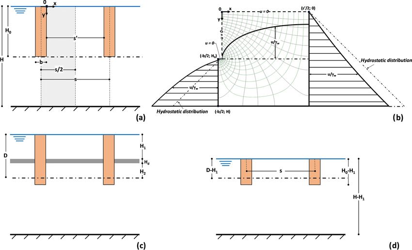
1670 G. Urciuoli et al.: Technical note: The beneficial role of a natural permeable layer
2 The basic model zone between parallel trenches are then at any time less than
hydrostatic (Fig. 1b). In contrast, beyond the bottom of the
The solutions presented below are based on the following trenches, the upward direction of the flow lines leads to a
assumptions: pore pressure distribution higher than hydrostatic. It is just
for this reason that the drains should always reach a depth
– The groundwater flow is two-dimensional.
close to the slip surface.
– Each soil layer is homogeneous, isotropic and charac-
terized by a linear elastic constitutive law. 3 Influence of a permeable layer located at an
– Total stresses are constant during the consolidation pro- intermediate depth between ground and slip surface
cess (this allows the analysis of the hydraulic and of the
3.1 Time of consolidation
mechanical soil responses to be uncoupled).
The governing equation of the problem (i.e. soil consolida- As outlined above, the presence of one or more persistent
tion induced by the draining elements) is the following: permeable layers in the soil body to be stabilized (a not un-
likely situation in deep clay deposits to be stabilized with
ht − cv2D hxx + hyy = 0, draining panels) may play a highly beneficial role in time lag
(1)
and the effectiveness of the drainage system.
where h = ζ + γuw and cv2D = 2(1+ν)(1−2ν)γ
KE
w
. The influence of a layer parallel to the ground surface, here
The technical literature reports solutions concerning the indicated as the “draining layer d”, featured by a thickness
case of parallel draining trenches and of tubular drains in ho- Hd as in Fig. 1c, has been investigated by FEM analyses
mogeneous soils, which are generally presented in the form using the code SEEP® (GEO-SLOPE Int. Ltd., 2012). The
of dimensionless design charts, providing the average effi- cases examined in this paper are indicated in Table 1; the re-
ciency, E (t, 0), along the slip surface 0: sults of the analyses are shown in a dimensionless form.
The data show that the presence of the permeable layer
u (0, 0) − u(t, 0) allows a considerable shortening of the time lag, here rep-
E (t, 0) = . (2)
u (0, 0) resented by the time factor, T90 , corresponding to an ef-
ficiency E (t90 , 0) = 90 % of the average steady-state effi-
In Eq. (2), u (0, 0) is the initial pore pressure on the slip sur- ciency E (∞, 0):
face, 0, and u (t, 0) is the average pore pressure at time t
modified by the draining elements; u (0, 0)is generally as- cv2D t90
T90 = . (3)
sumed to be hydrostatic. During the consolidation phase, H02
pore pressures decrease towards the minimum steady-state
value u(∞, 0), which is attained at time t → ∞ when the The value of t90 in Eq. (3) has been obtained by a numeri-
efficiency E (∞, 0) reaches the highest value. cal integration of Eq. (1), being the time at which E(t, 0) =
The available solutions for parallel trenches, featured by 0.90 · E(∞, 0) (see Eq. 2).
a thickness H0 and a width b, consider the soil volume be- Figure 2a and b, which report some results concerning
tween the two axes of symmetry, which respectively coincide the horizontal plane located at depth D = H0 , suggest quite
with the middle of a trench and the centre line between two a rapid attainment of E(t90 , 0), which is a crucial issue of
adjacent trenches (Fig. 1a). This volume is delimited by the the design. For significant values of trench spacing in the
ground surface and by an impermeable bottom surface lo- practice (i.e. s/H0 < 3), the following considerations may
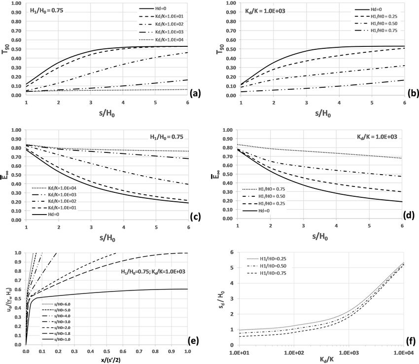
cated at the distance H from the ground surface. The ground be drawn: (i) for H1 /H0 = 0.75 and Kd /K = 100 (Fig. 2a),
and bottom surfaces are both horizontal: the slope angle is in- the dimensionless time T90 ranges between one-half and one-
deed assumed to play a negligible role in the hydraulic pro- third of the value that would be obtained in the absence of
cess (Aloi et al., 2019). The slip surface 0 is a horizontal the draining layer; (ii) for Kd /K = 1000 (Fig. 2b), T90 sig-
plane as well, located at depth D. In this paper it is assumed nificantly decreases with depth of the layer d (for H1 /H0 =
to be coincident with the base of the trenches (D = H0 ). 0.75, it drops to about 20 % of the value obtainable in ho-
A key hypothesis, which strongly affects the solution, is mogenous soils).
the presence of a permanent film of water at the ground sur-
face (Burghignoli and Desideri, 1987; D’Acunto and Urci- 3.2 Steady-state condition
uoli, 2006, 2010; D’Acunto et al., 2007). However, due to
The presence of a permeable layer allows higher values of
local formation of water ponding and saturation of vertical
E (∞, 0) to be obtained, and sooner than in homogeneous
cracks in the ground, often this is not far from the truth, at
soils. Some significant data are provided:
least during the wet season. Based on this assumption, the
pore pressure decrease is uniquely due to rotation of the flow i. Figure 2c, shows the steady-state efficiency for
lines towards the drainage trenches. Pore pressures in the H1 /H0 = 0.75 reported as a function of the ratio Kd /K
Hydrol. Earth Syst. Sci., 24, 1669–1676, 2020 www.hydrol-earth-syst-sci.net/24/1669/2020/G. Urciuoli et al.: Technical note: The beneficial role of a natural permeable layer 1671
Figure 1. (a) Schematic representation of the case at hand. (b) Flow lines and equipotential lines in homogeneous soil; piezometric heads
along the vertical axes at the middle of the trench, at the centre line between two adjacent trenches and on the horizontal plane at depth
of trench bottom. (c) Scheme with an intermediate permeable layer. (d) Equivalent scheme with a water film at the depth of the uppermost
boundary of layer d.
Table 1. Examined cases studied with FEM.
Numerical analyses Soil properties Geometry
by SEEP/W K Kd /K θ E ν H0 s/H0 b/H0 H /H0
(m s−1 ) – – (kPa) – (m) – – –
Homogenous soil model Hd = 0 10−7 , 10−9 – 0.5 15 000 0.3 10, 20, 30 1, 2, 3, 4, 5, 6 0.16 1, 1.5, 2.5
Stratified soil model H1 = 0.25H0 10−7 , 10−9 10, 100, 1000, 10 000 0.5 15 000 0.3 10, 20, 30 1, 2, 3, 4, 5, 6 0.16 1
Hd = 0.025H0 H1 = 0.50H0 10−7 , 10−9 10, 100, 1000, 10 000 0.5 15 000 0.3 10, 20, 30 1, 2, 3, 4, 5, 6 0.16 1, 1.5, 2.5
H1 = 0.75H0 10−7 , 10−9 10, 100, 1000, 10 000 0.5 15 000 0.3 10, 20, 30 1, 2, 3, 4, 5, 6 0.16 1
and of trench spacing. As shown, the higher the hy- sequence, pore pressure decrease, due to the action of
draulic conductivity of the draining layer, the higher layer d, increases with its depth.
the efficiency (as an example, for Kd /K = 1000 and
s/H0 = 3 it practically doubles). A major effect of layer iii. Figure 2e shows the non-dimensional pore pressure dis-
d is in fact diversion of a significant part of water com- tribution, ud , along the lower boundary of the drain-
ing from the ground surface towards the trench, thus ing layer d plotted as a function of trench spacing
strongly reducing water flow towards the slip surface. for H1 /H0 = 0.75 and Kd /K = 1000. Near the trench
boundary, the pressure head is less than Hd ; hence, a
ii. Figure 2d shows the efficiency for Kd /K = 1000 re- free water surface forms in the layer d (here water can
ported as a function of depth of layer d and trench spac- move towards the trench only below this surface, where
ing. The figure shows that it increases as the dimension- pore pressures are positive).
less distance, H1 /H0 , increases. The effect of layer d is
a strong pore pressure reduction at depth H1 . As a con-
www.hydrol-earth-syst-sci.net/24/1669/2020/ Hydrol. Earth Syst. Sci., 24, 1669–1676, 20201672 G. Urciuoli et al.: Technical note: The beneficial role of a natural permeable layer
Figure 2. Results of the FEM analyses (assuming H = H0 ). Dimensionless time, T90 , as a function of trench spacing and of (a) Kd /K ratio
for H1 /H0 = 0.75 and (b) H1 /H0 ratio for Kd /K = 1000. Average steady-state efficiency as a function of trench spacing and (c) Kd /K
ratio for H1 /H0 = 0.75 and (d) H1 /H0 ratio for Kd /K = 1000. (e) Dimensionless pore pressure over the lowermost boundary of layer d,
ud /(γw Hd ), as a function of x/(s 0 /2) and s/H0 , for Kd /K = 1000 and H1 /H0 = 0.75. (f) Values of sd /H0 as a function of Kd /K and
H1 /H0 .
A simplified approach to predict the steady-state value sd , according to the following expression:
condition
sd Hd H1 Kd
=f , , . (4)
H0 H0 H0 K
In the following, a simplified model for the optimization of
the design is briefly described. A very efficient working con- The values of sd /H0 in Eq. (4) have been obtained from the
dition is achieved if, at the centre line between two adjacent results of the numerical integration of Eq. (1). These have
trenches, the atmospheric pressure is attained at the upper- been reported in Fig. 2f, which shows the dependency of
most point of layer d. sd /H0 on Kd /K and H1 /H0 , having fixed Hd /H0 .
The first step in the design of the drainage system is just In case of full activation of layer d, the response of the
creating the conditions for full layer activation. This is ob- entire draining system may be analysed by a simplified ap-
tained when the spacing, s, of the trenches is equal to the proach. Since the fluid pressure at the uppermost boundary
Hydrol. Earth Syst. Sci., 24, 1669–1676, 2020 www.hydrol-earth-syst-sci.net/24/1669/2020/G. Urciuoli et al.: Technical note: The beneficial role of a natural permeable layer 1673
Table 2. Comparison among
steady-state efficiency values computed by Eq. (8), E (∞), and FEM analyses, E(∞)FEM ·
E(∞)FEM −E(∞)
1= % . Only results obtained for fully drained activation are reported (s ≤ sd ).
E(∞)FEM
H1 /H0 = 0.50 E(∞) E(∞)FEM
Kd /K = 10 1% Kd /K = 100 1% Kd /K = 1000 1% Kd /K = 10 000 1%
s/H0 = 1 0.766 0.780 1.73 0.783 2.10 0.783 2.10
s/H0 = 1.5 0.697 0.697 0.00 0.699 0.28
s/H0 = 2 0.642 0.646 0.54 0.651 1.30
s/H0 = 3 0.594 Draining layer not fully activated 0.601 1.08
s/H0 = 4 0.570 0.576 0.95
s/H0 = 5 0.556 0.559 0.53
s/H0 = 6 0.546
H1 /H0 =0.75 E(∞) E(∞)FEM
Kd /K = 10 1% Kd /K = 100 1% Kd /K = 1000 1% Kd /K = 10 000 1%
s/H0 = 1 0.821 0.833 1.41 0.834 1.50
s/H0 = 1.5 0.797 0.803 0.71 0.807 1.20
s/H0 =2 0.785 0.795 1.22
s/H0 = 3 0.773 Draining layer not fully activated 0.782 1.11
s/H0 = 4 0.767 0.774 0.83
s/H0 = 5 0.764 0.768 0.52
s/H0 = 6 0.761
of the layer d is equal to the atmospheric pressure (or to a mentioning that the solid lines in Fig. 2c and d for Hd = 0
small amount of suction, especially near the trench bound- are just those that are reported in the design charts.
ary), a water film may be fictitiously assumed at the same
depth (Fig. 1d). This obviously leads to a generalized pore
pressure decrease in the lowermost soil. In the following, any 4 Conclusions and final considerations
parameter referring to this fictitious condition will be indi-
cated by the apex ∗ . The aim of this paper is to demonstrate that the presence of
∗ soil layers of higher permeability, a not unlikely condition
The values of u∗ (∞, 0) and E (∞, 0) may be obtained
from the well known dimensionless solutions for the case of in some deep landslides in clay, may be exploited to improve
parallel trenches in homogeneous soil, as a function of spac- the efficiency of systems of drainage trenches for slope stabi-
ing (see the simplified scheme in Fig. 1d). The steady-state lization. Once the depth of the trenches, which should reach
efficiency is the slip surface, is established, the selection of proper spac-
ing may create a hydraulic system in which such layers can
u∗ (0, 0) − u∗ (∞, 0) work as additional drains. The problem has been examined
E ∗ (∞, 0) = , (5)
u∗ (0, 0) for the case that a unique permeable layer is present at an
thus elevation higher than the bottom of the trenches.
The results of numerical analyses show that it significantly
u∗ (∞, 0) = u∗ (0, 0) 1 − E ∗ (∞, 0)
speeds up the consolidation process triggered by drainages,
= γw (D − H1 ) 1 − E ∗ (∞, 0) .
(6) also leading to higher steady efficiency of the system. How-
It is worth noting that ever, as mentioned in the Introduction, in many practical
cases the design must take into account the time requested
u (∞, 0) = u∗ (∞, 0) (7) to achieve an adequate effective stress and safety factor in-
and crease. In these cases, trench spacing should be governed by
the T90 value.
u (0, 0) − u∗ (∞, 0)
E (∞, 0) = . (8) If pore pressures in the draining layer do not exceed the
u (0, 0) atmospheric pressure, a hydraulic disconnection forms be-
The values obtained from Eq. (8), through the value of tween the two parts of the landslide body located above and
u∗ (∞, 0) provided by mentioned solutions, have been com- below the layer, respectively. In such a way, the water film
pared to those obtained by FEM (Table 2). The good agree- which is normally assumed at the ground surface ideally
ment allows the proposed method to be validated. It is worth moves to the depth of the draining layer. This simple consid-
www.hydrol-earth-syst-sci.net/24/1669/2020/ Hydrol. Earth Syst. Sci., 24, 1669–1676, 20201674 G. Urciuoli et al.: Technical note: The beneficial role of a natural permeable layer eration allows the employment of the design charts available for the design of drainage trenches in homogeneous soils in the equivalent scheme characterized by groundwater level lo- cated at the depth of the draining layer, in order to calculate the final system efficiency. It is worth mentioning that the hydraulic continuity of layer d is a fundamental condition for the design. Consid- ering the variability and the unpredictability of many natural situations, proper investigations to check the validity of such an assumption are warmly recommended. In particular, the adoption of such a stabilization measure should always be managed through the “observational method”, i.e. by moni- toring the system response in order to (i) check the validity of the design and (ii) adopt proper modifications to it due to unexpected or neglected factors. The installation of piezome- ters is an obvious measure to check in real time the efficiency of the drainage system (especially during the critical rainy season). The piezometers should be installed both in proxim- ity to the slip surface (near and far from the trenches) and, if possible depending on thickness, in the permeable layer. This will allow the full activation of the permeable layer to be verified. Hydrol. Earth Syst. Sci., 24, 1669–1676, 2020 www.hydrol-earth-syst-sci.net/24/1669/2020/
G. Urciuoli et al.: Technical note: The beneficial role of a natural permeable layer                                  1675

Appendix A: List of symbols

 b            width of the trench
 cv2D         2D coefficient of consolidation
 d            draining layer
 D            depth of the slip surface
 E            Young modulus of the soil
 E(t, 0)      average efficiency of the draining trenches at time t along the sliding surface 0
 E(∞, 0)      average steady-state efficiency of the draining trenches along the sliding surface 0
    ∗
 E (∞, 0)     average steady-state efficiency of the draining trenches along the sliding surface 0 according
              to the simplified approach (full activation of layer d)
 γw           unit weight of water
 0            slip surface
 h            total head
 ht           first derivative of total head h with respect to time t
 hxx          second derivative of total head h with respect to abscissa x
 hyy          second derivative of total head h with respect to ordinate y
 H            depth of the impermeable bottom surface
 H0           depth of the base of trench
 H1           depth of the draining layer d
 Hd           thickness of the draining layer d
 K            coefficient of hydraulic conductivity
 Kd           coefficient of hydraulic conductivity of the draining layer d
 θ            soil moisture
 s            spacing between trenches
 sd           spacing between trenches creating the conditions for full activation of the draining layer d
 s0           distance between the boundaries of the trenches
 ν            Poisson ratio of the soil
 t            time
 t90          dimensional time corresponding to E (t, 0) = 90 % of the average steady-state efficiency
              E (∞, 0)
 T90          dimensionless time factor for E (t, 0) = 90 % of the average steady-state efficiency E (∞, 0)
 u            pore pressure
 ud           pore pressure at the base of the draining layer d
 u (0, 0)     initial pore pressure (time t = 0) on the slip surface 0
 u∗ (0, 0)    initial pore pressure (time t =0) on the slip surface 0 according to the simplified approach
              (full activation of the draining layer d)
 u (t, 0)     average pore pressure at time t on the slip surface 0, modified by drainage trenches
 u(∞, 0)      average steady-state pore pressure on the slip surface 0, modified by drainage trenches
 u∗ (∞, 0)    average steady-state pore pressure on the slip surface 0, modified by drainage trenches ac-
              cording to the simplified approach (full activation of the draining layer d)
 ζ            elevation head

www.hydrol-earth-syst-sci.net/24/1669/2020/                                   Hydrol. Earth Syst. Sci., 24, 1669–1676, 2020
1676 G. Urciuoli et al.: Technical note: The beneficial role of a natural permeable layer
Data availability. The datasets are freely downloadable from D’Acunto, B. and Urciuoli, G.: Groundwater regime in a slope sta-
https://doi.org/10.5281/zenodo.3518143 (Urciuoli et al., 2019). bilised by drain trenches, Math. Comput. Model., 43, 754–765,
2006.
D’Acunto, B. and Urciuoli, G.: Heavy rainfalls long term effects
Author contributions. GU and LP jointly conceived and set up the and mitigation with drains, in: Advances in environmental re-
research, discussing the issues with the other two authors, and wrote search, edited by: Aider, M. and Muller, T., Nova Science Pub-
the general parts of the paper in Sects. 1 and 2. LC and MP carried lishers, New York, USA, vol. 2., 323–347, 2010.
out numerical analyses and interpreted the results, discussing them D’Acunto, B., Parente, F., and Urciuoli, G.: Numerical models for
with the other two authors, and wrote the parts of the paper devoted 2D free boundary analysis of groundwater in slopes stabilized by
to commenting on the results, in Sect. 3. The contributions of the drain trenches, Comput. Math. Appl., 53, 1615–1626, 2007.
authors are equal. Desideri, A., Miliziano, S., and Rampello, S.: Drenaggi a Gravità
per la Stabilizzazione dei Pendii, Hevelius Edizioni, Benevento,
Italy, 1997.
Competing interests. The authors declare that they have no conflict GEO-SLOPE International Ltd.: Seepage modelling with SEEP/W,
of interest. Calgary, Alberta, Canada, 2012.
Hutchinson, J. N.: Assessment of the effectiveness of corrective
measures in relation to geological conditions and types of slope
movement, Bulletin of the International Association of Engineer-
Financial support. This research has been developed within the
ing Geology, 16, 131–155, 1977.
framework of the PRIN 2015 project titled “Innovative Monitoring
Pun, W. K. and Urciuoli, G.: Soil nailing and subsurface drainage
and Design Strategies for Sustainable Landslide Risk Mitigation”,
for slope stabilization, in: Proceedings of 10th International
supported by the Italian Ministry of Education, University and Re-
Symposium on Landslides and Engineered Slopes, 30 June–
search (MIUR) (grant no. 201572YTLA).
4 July 2008, Xi’an, China, Keynote paper, 85–126, 2008.
Stanic, B.: Influence of drainage trenches on slope stability, J.
Geotech. Eng.-ASCE, 110, 1624–1635, 1984.
Review statement. This paper was edited by Nadia Ursino and re- Urciuoli, G.: Pore pressures in unstable slopes constituted by fis-
viewed by two anonymous referees. sured clay shales, Proceedings of the Second International Sym-
posium on Hard Soils-Soft Rocks, 12–14 October 1998, Naples,
Italy, 1177–1185, 1998.
Urciuoli, G. and Pirone, M.: Subsurface drainage for slope stabi-
References lization, in: Landslide Science and Practice, edited by: Margot-
tini, C., Canuti, P., and Sassa, K., Springer, Berlin, Heidelberg,
Aloi, F., Pirone, M., and Urciuoli, G.: Numerical inves-
Germany, vol. 6, 577–585, 2013.
tigation of small- and medium-diameter drain wells to
Urciuoli, G., Comegna, L., Pirone, M., and Picarelli, L.:
stabilise deep landslides, Acta Geotech., 14, 1065–1080,
The beneficial role of stratigraphy on slope stabilization by
https://doi.org/10.1007/s11440-018-0688-8, 2019.
drainage trenches: results of FEM numerical analyses, Zenodo,
Bromhead, E. N.: An analytical solution to the problem of seepage
https://doi.org/10.5281/zenodo.3518143, 2019.
into countfort drains, Can. Geotech. J., 21, 657–662, 1984.
Burghignoli, A. and Desideri, A.: On the effectiveness of tubu-
lar drains, in: Proceedings of the IX ECSMFE, 31 August–
3 September 1987, Dublin, Ireland, vol. 1, 121–124, 1987.
Hydrol. Earth Syst. Sci., 24, 1669–1676, 2020 www.hydrol-earth-syst-sci.net/24/1669/2020/You can also read