OPTIMIZATION OF ENERGY EXTRACTION USING DEFINITE GEOMETRY PRISMS IN AIRFLOW
←
→
Page content transcription
If your browser does not render page correctly, please read the page content below
LATVIAN JOURNAL OF PHYSICS
                                                               AND TECHNICAL SCIENCES
                                                                              2021, N 2

                                                               DOI: 10.2478/lpts-2021-0009

OPTIMIZATION OF ENERGY EXTRACTION USING
  DEFINITE GEOMETRY PRISMS IN AIRFLOW

                   I. Tipans, J. Viba, M. Irbe* and S. K. Vutukuru

       Faculty of Mechanical Engineering, Transport and Aeronautics,
                         Riga Technical University,
                   6B Kipsalas Str., LV-1048, Riga, LATVIA
                        *e-mail: martins.irbe@rtu.lv

      An approximate method for analysis and synthesis of moving rigid bodies (prisms)
in the airflow without using numerical methods of space-time programming techniques is
described by applying a fluid (air)–rigid solid body interaction concept for engineering appli-
cations through a straightforward mathematical model. The interaction of rigid body (prism)
and air is encountered in different cases: moving body (prism) in the air; stationary bodies
(prism) in the airflow; moving body (prism) in the airflow. The complicated task of rigid body
(prism) and air interaction is simplified by using superposition principles, i.e., by taking into
account the upstream and downstream rigid body (prism) and air interaction phenomenon,
which has been found to be different under varying speeds. Numerical results obtained for
various forms of prisms are shown for constant air–speed, where the steady state Reynolds-
averaged Navier–Stokes (RANS) equation is solved by using k-ε realizable turbulence model.
A detailed explanation to support the proposed approximate method is given by using numeri-
cal results obtained in ANSYS computations. All equations are formed based on laws of clas-
sical mechanics; the interaction of viscous forces is neglected in forming the mathematical
model. Numerical results for different model prisms are compared and the theoretical results
discussed in detail. The mathematical model in the present paper is applicable only to bodies
that undergo a rectilinear translation motion. In the final part of the present paper, the proposed
method is used in the synthesis and optimization task of energy extraction by considering the
motion of a variable parameter prism in the airflow.
     Keywords: Rigid body (prisms), superposition principle, space-time programming.

                                                19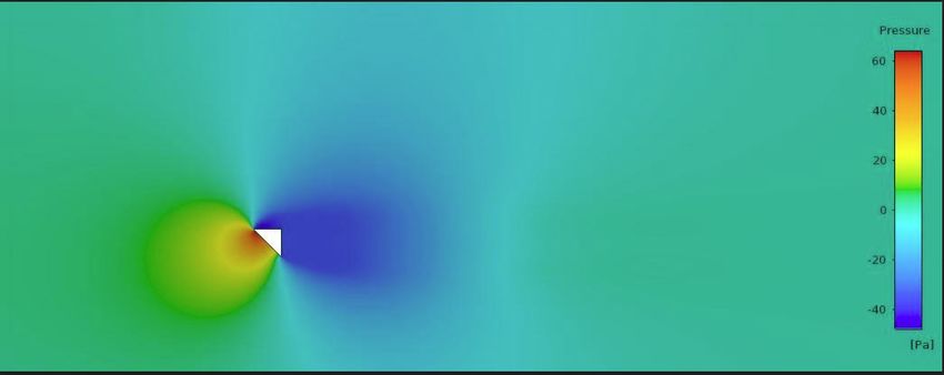
1. INTRODUCTION

     The theme of the interaction between              simulations of deforming structures could
the solid (rigid) body and fluid still plays an        be performed effectively [9]. Easily under-
important role in science, technology, pro-            standable and less complex method for
duction processes and in everyone’s life.              space–time mesh that allows for refinement
     In the present paper, three possible cases        of the selected locations within the domain
of fluid–rigid body interaction are studied:           was also proposed [10]. Advantage of sav-
stationary rigid body in the air, non-station-         ing the computational time, accounting
ary body in the air and non-stationary body            for flexibility of unstructured meshes and
in the airflow. Though good research per-              improving the scope of compressible fluid
taining to non-stationary rigid body–fluid             flow were mentioned in [11]. Solution for
interaction in fluid flows is available, no            non-stationary fluid body problems by using
one can deny the fact that understanding               a high-order finite element method based on
the phenomena requires advanced program-               space–time discontinuous Galerkin (DG)
ming skills (space–time techniques) along              procedure was proposed and extended to
with in-depth knowledge of CFD and core                explain the dynamics of parachute motion
engineering mathematics. General mesh                  [12]. A simple method using the concept of
deforming and re-meshing techniques are                zones, averting the space time programming
time consuming and strictly have geometry              techniques and extending the concept for
constrains and many times are computa-                 energy extraction for simple form objects
tionally expensive. A better method com-               was performed in [13]. In the present study,
pared to moving and deforming techniques               without using any numerical space–time
with no restriction on closeness between               programming techniques and in a straight-
objects and their complex motion is studied            forward way using the averaged principle
where continuity and momentum equations                of superposition, fluid interaction with rigid
include motion effects [1]. Different types            body is explained. The entire paper specifi-
of mesh moving techniques for fluid–struc-             cally focuses solely on rigid body–fluid (air)
ture interaction were studied and compared.            interaction, does not consider flow reattach-
A new use of space–time discretization that            ment or flow separation phenomenon and
could be extended for a full-time space                offers an alternative to a vortex induced
Galerkin discretization was examined [2].              vibration concept [14]–[16] and the same
Fixed mesh technique by using arbitrary                study is further extended for energy extrac-
Lagrangian–Eulerian approach for flow                  tion by using variable parameters of defi-
problems in a moving domain was studied                nite geometry–prism. The main idea of the
and for every time step results were dis-              article is to propose a simplified approach
played on a background mesh [3]–[7]. An                to an interaction phenomenon and to offer
algorithm for space–time finite element                an alternative to vortex induced vibration
meshes was used to obtain numerical results            techniques through a mathematical model
for transient Navier–Strokes equations for             that does not consider the viscous effects
an adaptive moving mesh in time [8]. New               of fluid (air) but the viscous effects are in a
XFEM approach was proposed based on a                  way indirectly resulting from the mathemat-
fixed grid method, which did not take into             ical model by considering the output from
account most of fluid unknown charac-                  steady state numerical simulations (RANS
teristics. This method is advantageous as              by K-ε turbulence model) in ANSYS.

                                                  20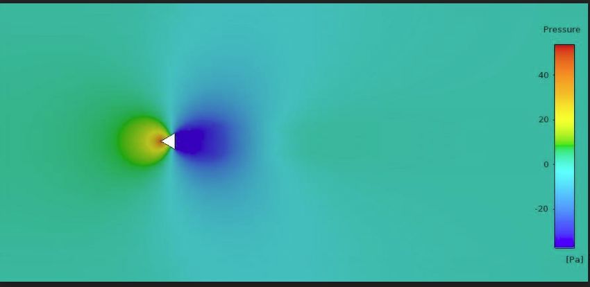
2. MATHEMATICAL MODELS FOR
FLUID (AIR) STRUCTURE INTERACTION

    Keeping in view the much-needed tasks             ing a laminar flow for the incompressible
of analysis, synthesis and optimization that          fluid. However, the mathematical model
are required in many engineering applica-             does not include the viscous nature of the
tions, the present paper offers an averaged           fluid under consideration.
mathematical model approximately assum-

            Fig. 1. External relative flow over a moving prism in very low speed airflow.

    The space around the body under con-              action phenomenon.
sideration when subjected to fluid is care-               The mathematical model is described in
fully studied; a straightforward mathemati-           the case of definite geometry shaped prism
cal model using classical laws of mechanics           (Figs. 1–3).
is explained based on a fluid structure inter-

       Fig. 2. Interaction of the rectilinear                Fig. 3. Model of air interactions
    translation (non-rotating) motion body in                     with stationary prism.
                   windless air.

     Considering the very small air element           ing to the principle proposed in the present
in the pressure zone, we use the momentum             paper (superposition principle), taking in
change in the differential form. Accord-              the projection of the area normal n1, before

                                                 21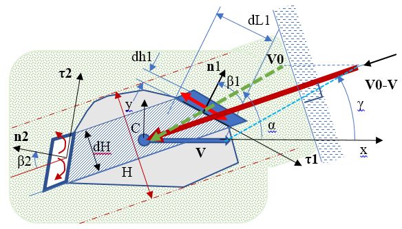
and after collisions (fluid–body interac-             where m1 – prism and air interaction bound-
tion), we obtain (1): from Brownian inter-            ary layer mass; v – prism velocity; β1 – an
action to prism:                                      angle between velocity and normal ;
                                                      ∆N1 – additional normal force acting on a
                                                      prism; ∆p1 – pressure increase in the pres-
                                                      sure zone.
                                           (1)
                                                          From the system of six equations (1),
                                                      (2) it is possible to find six unknowns. The
where m10 – Brownian interaction mass;                two unknowns are required to solve the fol-
VB1 – an average air normal velocity in               lowing calculations:
the pressure zone; N1 – normal force to a
small element from the air; dt – an infinitive                                                 (3)
small time interval; dL1 – width of a small
                                                                                               (4)
element; B – prism height perpendicular
to the plane of motion; ρ – density of air;
p10 – atmospheric pressure in the pressure                Accordingly, it is possible to apply
zone.                                                 equations like (1)–(4) in the suction zone
                                                      (leeward side). However, the task is little
    From prism air interaction at windward            complicated with the number of momentum
side (pressure side) (2):                             differentials in the suction zone: it is not
                                                      clear how to simplify the equations in dif-
                                                      ferential form. Therefore, it is suggested to
                                          (2)         use one or the other hypothesis. Hypotheses
                                                      should be tested experimentally or by using
                                                      computer applications.

The first hypothesis

   In the suction zone, pressure reduction                                                     (6)
∆p21 over the entire surface is constant and          where C1 – a constant found according to
proportional to the square of the velocity v.         the experimental or numerical modelling;
   We get:                                            VB2 – an average air normal velocity in the
                                          (5)         suction zone.

The second hypothesis

    In the suction zone, pressure reduction                                                    (7)
∆p22 over the entire surface is not con-
                                                                          ,                    (8)
stant but is proportional to the square of the
velocity v and also depends on the normal             where C2 is the second constant found in
n2 to the surface area and position angle β2.         the same way as C1.
Thus, we obtain (7), (8):

                                                 22
The obtained differential relationships For practical engineering calculations, (3)–(8) can be used in the engineering anal- it is recommended to adopt VB1 = VB2 ysis and synthesis tasks in the low speed for low velocity v
(9)
(10)
where Vr – a relative velocity module; V0 – wind velocity as a vector; V – prism rectilinear
translation motion velocity as a vector and α is a V0 flow angle (Fig. 4).
By using the obtained relationships lems of energy extraction from a fluid (air)
(3)–(8), it is possible to solve various tech- stream. Additionally, it is also possible to
nical tasks of fluid (air) and prism motion optimize the shape of the object (prism) in
for engineers. For example, it is possible to order to obtain the desired effect (criterion)
carry out motion analysis tasks where air- along with motion control task optimization
flow resistance forces can be obtained. It is and real system synthesis by using mecha-
even more important for solving the prob- tronic systems.
5. NUMERICAL EXPERIMENT
In the proposed airflow interaction able turbulence model. The sharp prism
averaging superposition method, the engi- with two sides (other than the longest side)
neer calculations require the selection of was 0.16 m and the depth was maintained
an approximation model, which in turn constant at 0.16 m. In the given numerical
requires numerical values of constants C1 experiment, knowing the total flow force
or C2. Fx, constant C1 was found according to the
Thereby, in this direction 3D-RANS formulas above. The numerical values of Fx
equation was solved by using K-ε realiz- and constant C1 are given in Figs. 5, 6.
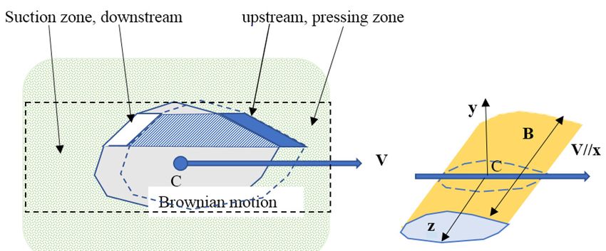
Fig. 5. Sharp right-angle Isosceles prism (angles 45° , 45°, 90° ) with leading vertex 45°
in stationary airflow. Quality distribution of pressure in suction and compression zones.
Fx1 = 1.8942 N; C1 = 0.238.
Fig. 6. Equilateral triangle (angles 60° , 60°, 60° ) sharp prism in airflow with leading vertex 60°.
Distribution of pressure in suction and compression zones. Fx2 = 1.3680 N; C1 = 0.245.
246. CONCLUSIONS OF THE 3D NUMERICAL SIMULATION
1. Theoretical calculations for the 2D total force can be found according to the
model differ from the 3D numerical methodology proposed here, for a con-
simulation. stant narrow range: 0.238 < C1 < 0.245
2. Visually, the first and second hypotheses (Figs. 5, 6).
(C1, C2) come true because the pressure 5. It is known from scientific experimental
in the suction zone is approximately the studies that the difference between 3D
same at all locations (Figs. 4, 5). and 2D drag coefficients is about twice.
3. Pressure zone in different local places Therefore, C ≈ 0.5 should be used in
is different. approximately 2D calculations; this
4. In spite of the deviations of the pres- value is further used in all future cal-
sure from the constant along the edges culations.
of the pressure zone of the prism, the
7. OPTIMIZATION OF TRIANGLE PRISM IN
RECTILINEAR TRANSLATION MOTION IN AIRFLOW
The motion model with given length moment, providing a rectilinear translation
and angles is shown in Fig. 7, where motion of a triangle prism.
and are the external forces and
Fig. 7. Triangle prism movement in the wind direction Vr // V // x.
The optimization task should determine Here,
the prism braking velocity V that provides
the maximum power in the mechatronic
system. The differential equation of motion where m is a prism mass; – constrained
will be (11): acceleration along x axis; Q – braking force.
(11)
25The task of optimization is the follow- braking mechatronic system shall be found
ing. to provide the maximum power P produced
Given for motion parameters C0, m by the airflow force.
for stationary motion, when acceleration is In the given case, without limitation,
zero ( = 0), the force Q of the prismatic there is an optimal solution as given by (12):
(12)
As can be inferred from Eq. (12), (if requires a mechatronic force control Q sys-
the flow rate V0 changes) the real system tem.
8. MOTION OF A SHARP PRISM IN A VERTICAL PLANE
We observe the movement of a sharp model mentioned above (use of a constant
prism in a vertical plane, when angles are C1), the motion of a sharp prism in a verti-
equal β22 = β21 = β1 (Fig. 8). cal plane is described by differential equa-
According to the theory of the first tions (13), (14):
(13)
(14)
where and are acceleration projections; α – an angle between normal and vertical direc-
tion; sign is a ±1 depending on the function in brackets; g – free fall acceleration.
The obtained equations allow solv- diving movement in the air.
ing analytical and parametric optimization Example of diving motion calcu-
problems for a given non-stationary motion lation is shown below (Figs. 8–11).
case. In addition, it should be noted that this All parameters in system SI:
movement is close to the bird’s gliding or
Fig. 8. The trajectory of the centre of mass Fig. 9. Speed projection on
motion in the vertical plane, starting prism normal.
from the coordinates (x, y) = (0, +100).
26Fig. 10. Frontal force of air interaction. Fig. 11. Total acceleration of prism fall and lateral
slip. The figure shows that the viscous forces
mentioned at the beginning of the article are not
taken into account.
The obtained modelling results show tangent direction becomes constant, but the
that the velocity projection perpendicular to velocity component increases linearly with
the sharp prism reaches the terminal value time. This means that in real-world applica-
and does not change further. However, there tions, viscosity must be observed or a real
is no acceleration component in this direc- prism with a blunt front surface must be
tion. Accordingly, the acceleration in the considered.
9. SYNTHESIS AND OPTIMIZATION TASK OF ENERGY EXTRACTION
For the description of the given prob- the prism is attached to a base with elastic
lem, we will use the previously obtained spring 3. The energy is obtained by elec-
relation for sharp triangular prism 1, whose trodynamic braking system 4. According
motion is relative to wind flow 2 (Fig. 12). to expressions such as (11), the differential
The movement is along the x axis an angle equation of motion is (15):
α to the flow. We consider the case where
(15)
where f(x) – a spring characteristic; D( ) – force of an electrodynamic braking system; A – a
prism area of the pressure zone, as before: .
Fig. 12. Model showing the working principle for energy extraction using the phenomenon of
air–body (prism) interaction with sharp triangular prism 1, wind flow 2, elastic spring 3, and
electrodynamic braking system 4.
27The resulting equation (15) allows solv- problem where there can be change in area
ing all kinds of analytical, optimization and A realized by using the perforated plate.
synthesis problems if a criterion with given Taking into account case of linear spring
constraints on system and control param- with a linear electrodynamic braking sys-
eters is formulated. tem, equation (15) is expressed as (16):
As an example, we solve a synthesis
(16)
where c – elasticity of spring; b( ) – electrodynamic system control force; A( ) – area
variation control action depending on the synthesis task of velocity, coordinate and time.
The energy optimization task should
analyse the power P of the electrodynamic
system (17):
(17)
10. MODELLING OF VARIABLE AREA PRISM IN AIRFLOW
Let us consider the possibility of obtain- the simplest direction of the wind flow par-
ing energy from the flow if the change of allel to the prism motion axis α = 0 and with
area occurs instantaneously when opening optimal angle β = 0 (Fig. 12). Then the dif-
or closing the perforation. Let us assume ferential equation of motion will be (18):
(18)
where b, C1, a0, a1, ∆v are constants.
Equation (18) has to be solved numeri- system. The results obtained are shown in
cally by estimating the efficiency of energy Figs. 13–16 for parameters: m = 0.5 kg;
production by criterion (17) as power. c = 80 kg‧sec-2; b = 0.5 kg‧sec-1; C1 = 0.5;
Modelling example for a small plate A = 0.04 m2; a0 = 0.75; a1 = 0.25; ∆v = 0.5 m
is given below; all values are used in SI sec-1; ρ = 1.25 kg m-3; V0 = 10 m sec-1.
28Fig. 13. Displacement with respect to time Fig. 14. Velocity with respect to time for
for a variable area prism. a variable area prism.
Fig. 15. Phase plane motion. Fig. 16. Power generated for the given
time interval.
From the graphs in Figs. 13–16, the fol- 2. The opening and closing of perforations
lowing conclusions can be drawn: may be affected by a mechatronic sys-
tem.
1. In the aerodynamic system it is possible 3. There is the second mechatronic system
to initiate a stable oscillation movement for generating energy, which breaks
by changing the interaction area of the the speed of oscillation and generates
perforated plate. power.
11. RESULTS AND DISCUSSION
Within the framework of the present of interaction (constant) is introduced from
study, we have developed a new method for numerical simulation results. Stable result
calculating the approximate flow and rigid in case of a variable area prism for energy
body interaction for: a moving body in the extraction has been observed (see Fig. 15).
low speed air, a stationary body in the air- Though the power obtained is small, the
flow and a moving prism in the airflow. The proposed theory (superposition principle)
fluid flow is assumed to be laminar, incom- helps identify the cause and make a way for
pressible, and viscous nature of the fluid overall better efficiency as the nature of the
is not taken into account for mathematical proposed principle is purely mathematical
modelling, as an alternative the coefficient and is explained in an easily understandable
29and straightforward way. Good and satis- tion phenomenon other than the traditional
factory results are obtained both for moving vortex induced vibration techniques has
prisms in the airflow and energy extraction been found to be successful in calculating
by using a variable area prism. An alternate energy extraction by means of a simple
approach to a solid body–fluid (air) interac- mathematical model.
12. CONCLUSIONS
The method developed in the present posed method in engineering calculations.
study helps perform tasks of analysis, opti- The present study also establishes the
mization and synthesis for the interaction of fact that there is an alternate approach to
objects with fluids in a simplified way, only vortex induced vibration phenomenon for
for rectilinear translation motion of body. the energy extraction process considering
The proposed techniques help overcome the just the body–fluid interaction coefficient
extensive space–time programming meth- in a straightforward mathematical model.
ods. The analysis, optimization and com- The theory can be extended to any complex
puter modelling examples discussed in this body–fluid interaction as the work is purely
paper illustrate the effectiveness of the pro- mathematical in nature.
ACKNOWLEDGEMENTS
This research has been funded by Interacting with Bulk Solids and Fluids”,
the Latvian Council of Science, project project No. Lzp-2018/2-0281 and sup-
“Creation of Design of Experiments and ported by the Doctoral Grant programme of
Metamodelling Methods for Optimization Riga Technical University.
of Dynamics of Multibody 3D Systems
REFERENCES
1. Wei, G. (2005). A Fixed-Mesh Method for 4. Tezduyar, T. E., Sathe, S., Keedy, R., &
General Moving Objects in Fluid Flow. Stein, K. (2006). Space-Time Finite Element
International Journal of Modern Physics B, Techniques for Computation of Fluid-
19 (28), 1719–1722. Structure Interactions. Comput. Methods
2. Wick, T. (2011). Fluid-Structure Interactions Appl. Mech. Eng., 195, 2002–2027.
Using Different Mesh Motion Techniques. 5. Tezduyar, T. E., & Sathe, S. (2007).
Journal of Computers and Structures, 89 Modelling of Fluid-Structure Interaction
(13), 1456–1467. with the Spacetime Finite Elements:
3. Codina, R., Houzeaux, G., Coppola- Solution Techniques. Int. J. Numer. Meth.
Owen, H., & Baiges, J. (2009). The Fixed- Fluids, 54, 855–900.
Mesh ALE Approach for the Numerical 6. Han, D., Liu, G. R., & Abdallah, S. (2020).
Approximation of Flows in Moving An Eulerian-Lagrangian-Lagrangian Method
Domains. Journal of Computational Physics, for 2D Fluid-Structure Interaction Problem
228 (5), 1591–1611. with a Thin Flexible Structure Immersed in
Fluids. Computers & Structures, 228, 106179.
307. Takizawa, K, & Tezduyar, T. E. (2011). 12. Diosady, L.T., Murman, S.M., & Carton de
Multiscale Space-Time Fluid-Structure Wiart, C. (2018). A higher order space time
Interaction Techniques. Comput. Mech., 48, finite element method for moving body and
247–267. fluid structure interaction problem. In 10th
8. Neumuller, M., & Steinbach, O. (2011). International Conference on Computational
Refinement of Flexible Space-Time Finite Fluid Dynamics (ICCFD10) (pp. 1–16),
Element Meshes and Discontinuous 9–13 July 2018, Barcelona, Spain.
Galerkin Methods. Computing and 13. Tipans, I., Viba, J., Irbe, M., & Vutukuru, S.
Visualization in Science, 14, 189–205. K. (2019). Analysis of Non-Stationary Flow
9. Gerstenberger, A., & Wall, W. A. (2006). Interaction with Simple Form Objects.
An Extended Finite Element Method Based Agronomy Research, 17 (1), 1227–1234.
Approach for Large Deformation Fluid- 14. Barrero-Gil, A., Pindado, S., & Avila, S.
Structure Interaction. European Conference (2012). Extracting Energy from Vortex-
on Computational Fluid Dynamics. Induced Vibrations. A Parametric Study.
ECCOMAS CFD, Netherlands, TU Delf. Applied Mathematical Modelling, 36 (7),
10. Behr, M. (2008). Simplex Space-Time 3153–3160.
Meshes in Finite Element Simulations. 15. Bearman, P.W. (1984). Vortex Shedding
International Journal for Numerical from Oscillating Bluff Bodies. Fluid Mech.,
Methods in Fluids, 57 (9), 1421–1434. 16, 195–222.
11. Danwitz, M. V., Karyofylli, V., Hoster, N., 16. Chin, D. D., & Lentink, D. (2016). Flapping
& Behr, M. (2019). Simplex Space-Time Wing Aerodynamics: From Insects to
Meshes in Compressible Flow Simulations. Vertebrates. J. Exp. Biol., 219, 920–932.
International Journal for Numerical
Methods in Fluids, 91 (1), 29–48.
31You can also read