Generating Air Ionization With No Contaminating Particles
←
→
Page content transcription
If your browser does not render page correctly, please read the page content below
Proc. ESA Annual Meeting on Electrostatics 2011                                                 1

       Generating Air Ionization With No
           Contaminating Particles
                                Larry Levit1 and Douglas Beyer2
               1                                              2
                   LBL Scientific                                 ESD Company LLC.
           1865 Monte Sereno Dr                               1408 Elizabeth Crest
             Alamo, CA 94507                                  Redlands, CA 92373
            Phone: 925 788 2969                               Phone: 909 806 -0382
  Email: LBL_Scientific@LBLevit.com                      Email: douglasesd@gmail.com

   Abstract—Modern semiconductor manufacturing employs air ionizers to reduce the effects
of static charge. These effects are contamination control from electrostatic attraction and on
physical damage from discharges. Conventionally, air ionization is generated by corona from
needle electrodes, but there are particles generated by this process. In the past, these particles
have been too small to affect the manufacturing process, but this is no longer true. The latest
small structures on the wafer have reached the limit where these particles will harm the prod-
uct. This paper discusses the mechanism for particle creation and presents a design which
creates no particles.

                                      I. INTRODUCTION
   Semiconductor, flat panel and disk drive manufacture all suffer from yield loss from
physical damage to the product caused by discharge. Such discharges sometimes create
sufficiently high electromagnetic impulses to confuse the microprocessor in automated
equipment1. In addition, contamination is an issue in part of each of these processes. Elec-
trostatic attraction arising from static charge greatly increases the amount of contamina-
tion landing on the product during manufacture2,3. Each of these effects is reduced
through the use of air ionization. Ions add conductivity to the air and provide a path to
ground for surface charge on insulators and floating conductors.
   Typically, air ionizers employ high voltage on sharp needle electrodes. There are sev-
eral mechanisms (discussed below) by which this ionization process generates unwanted
particles. There has been quite a bit of work done on selecting the needle electrode ma-
terial, sharpness voltages levels employed, and the waveforms of the high voltage signals.
All of these design improvements have served to reduce but not eliminate the particle
generation effect4. Particle generation results in both contamination and white fuzz balls
on the needle electrodes which, inter??, reduce the generation of air ions and eventually
defeat the action of the ionizer. The development of so-called clean ionizers have limited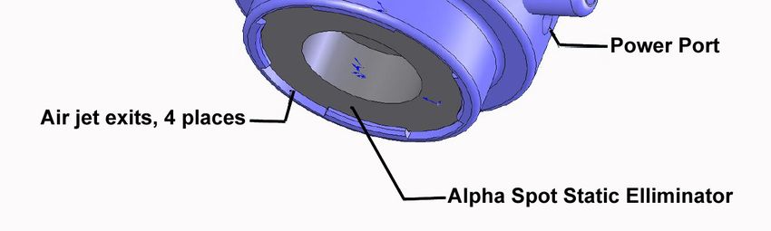
Proc. ESA Annual Meeting on Electrostatics 2011                                                            2

particle generation to nano-particles which could be ignored until recently, when semi-
conductor manufacturing started to produce devices with nano-scale features. See Figure
1. The mechanisms by which corona ionizers generate gas-to-particle conversion are well
understood and will be discussed below. The effect is inherent to the process and im-
proved designs can only serve to minimize such particle generation and not eliminate it.

Figure 1. International Technology Roadmap for Semiconductors shows the evolution of smaller and smaller
                                      feature sizes on microchips.

   Air ionization can be generated by the use of radioactive isotopes which dissipate the
kinetic energy of particles from radioactive decay through ionization of the medium
through which they pass. The process is self sustaining and has no chemical/particle crea-
tion consequences because it does not involve high temperature plasma as does the co-
rona ionizer. Tthe hybrid process was first proposed by Wilson5 who did some initial test-
ing but never produced a product. We report construction and testing of such a product
with the addition of compressed gas delivery.

                                     II. THE CORONA IONIZER

  The corona ionizer employs needle electrodes which are biased to a high voltage (10-20
kV) to create air ions. Both DC and AC ionizers are available. Corona ionizers create
particles both by erosion of the emitter tips, and by their plasma at the needle tips acting
as a chemical reactor and converting airborne molecular contaminants (AMCs) to small
particles which, in turn, agglomerate into larger ones.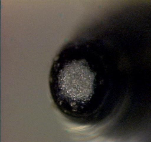
Proc. ESA Annual Meeting on Electrostatics 2011                                                                3

  Generally, the cleanest ionizers (most erosion free) are the ones that run at the lowest
power output. The electron current from a needle electrode can cause pitting of adjacent
material or of the emitter electrodes themselves. See Figure 2. This result in large (~0.1-5
µm) particles of emitter material being liberated from the needle electrode into the envi-
ronment of the cleanroom. This is minimized by using a configuration that avoids recom-
bination of positive and negative ions so that the ions received at the charged object will
be adequate in numbers, while the power dissipated at the emitter tip is minimized.

Figure 2. Pitting of a corona ionizer's needle elec-          Figure 3. Corona needle electrode with fuzzball6 .
                       trode.

  The second effect, gas to particle generation, involves effectively cooking AMCs at the
emitter tips. Some of the particles are collected on the needle electrodes (Se Figure 3) The
ionizer creates a low energy plasma at the emitter tip which achieves a rather high tem-
perature due to Joule heating. This temperature has been calculated by the authors. The
power dissipated into the plasma is given by

                                                       W=iV                                  (1)

   Here i is the corona current drawn by the needle tip and V is the potential to which the
needle electrode is biased. The model used for this calculation is shown in Figure 4. Tak-
ing the power to be dissipated by conduction up the needle electrode (black body radia-
tion was ignored) with

                                                2 < i < 10 µA and                            (2)

                                            10 kV < V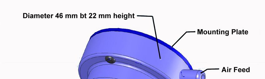
Proc. ESA Annual Meeting on Electrostatics 2011                                                            4

   The temperature elevation above ambient for Silicon or Silicon Carbide emitter elec-
trodes is in the range 200-1000oC over a volume of 0.7 mm3. This will disassemble com-
plex organic solvents which are dissolved in the air as they pass through the emitter tip.
These AMCs form a "soup" of free radicals which recombine into various permutations of
the original atomic constituents of the AMCs that traveled past the emitter tip. These
small particles are attracted to the needle electrode by the dielectrophoretic force which is
attractive no matter what the polarity of the electrode7.

     Figure 4. The model used for calculating the temperature of the plasma at the needle electrode tip.

   As the small nano-particle is drawn into the electrode, it agglomerates additional ma-
terial and grows. Typically the particles achieve a size of 5 to 50 nm which will certainly
interfere with fabrication of modern 25 nm structures if they land on the wafer.

  The first step in reducing this effect is to use an electrode material which has good me-
chanical and thermal conductivity properties. Both Silicon and Silicon Carbide stand out
for this application. While there are some waveforms7 which reduce the magnitude of the
effect and the size of the particles, such techniques do not eliminate the particles.

                           III. THE ALPHA PARTICLE-BASED IONIZER

       Alpha particles, being Helium nuclei, are substantially heavier than other radioac-
  tive decay particles. For example, an α particle is ~8000 times more massive than a β
  particle. For that reason, it travels much more slowly than a β of the same energy. At
  the lower speed, its electric field has more time to deliver energy to molecules it passes
  close to and, thus, it causes much greater deposition per unit path length than the com-
  parable β. See Figures 5 and 6. Alpha particles from Po210 have an energy of 5.4 MeV
  and travel only ~4 cm in air. Each Alpha creates approximately 250,000 ion pairs along
  its path length. In contrast, the ion density from Beta radioactivity is much less concen-
  trated and, hence, less effective at controlling static charge.
Proc. ESA Annual Meeting on Electrostatics 2011 5
Conservation of charge dictates that Alpha particle-based ionizers create a perfect-
ly balanced population of positive and negative ions with no need for adjustment. Also,
because they do not have a high density, high temperature plasma, they do not create a
high concentration of free radicals or agglomerate them into nano -particles.
Figure 5. Range of Alpha and Beta particles in Figure 6. Energy deposition rate for Po210
air. Alpha particles in air.
As can be seen from Figure 6, the air ionization created by an alpha particle-based io-
nizer is located within 4 cm of the source. Charge on adjacent objects (within ~10 cm)
will be dissipated because the fields from the charged object will draw the ions to it.
Beyond that distance, other means are required to cause the ions to travel to the target
charged object. For example, the disk drive industry employs Alpha-based ionizers along
with a blower (fan) to deliver ions over a distance of 30-60 cm. The choice of Alpha
technology is based upon the sensitivity of the delicate magneto-resistive heads to dis-
charge, and the fact that the perfectly balanced Alpha ionizer cannot create an offset vol-
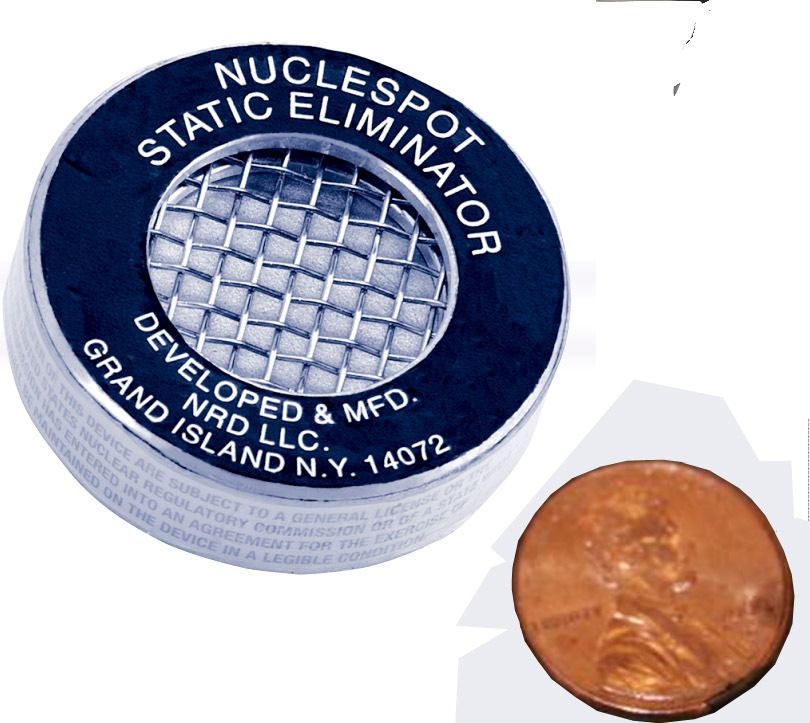
tage on the product or anything in the environment. A small Alpha ionizer (~2.5 cm
across) is shown in Figure 7 and the AlphaBoost product is shown in Figure 8..
Figure 8. The AlphaBoost Ionizer Structure Figure 7?
Figure 7. A NRD Nucleospot 5 mCi Alpha IonizerProc. ESA Annual Meeting on Electrostatics 2011 6
Unfortunately, blowers or compressed gas cannot be used to move the ions to the target
in clean rooms which employ unidirectional flow (laminar flow) to achieve extreme con-
tamination control (Federal Standard 209E class 10 = ISO 14644 - 1 ISO Class 4). For
this reason, Wilson5 stole a trick from the corona ionizer design. Corona ionizers are
sometimes mounted on the ceiling of a cleanroom and the air flow from the HEPA filters
is used to move the ions down to the target charged objects. Often the ceiling can be as
much as 4 meters high and without special precautions, virtually all of the ions entrained
in the unidirectional flow find ions of the opposite polarity and recombine.
Corona ionizers mounted on the ceiling often use a technique called pulsed DC. This
involves applying a high potential to one needle electrode and then to the other. By puls-
ing the system very slowly, the positive and negative ions are separated from each other
so that recombination is dramatically limited. At the limit, only one polarity of ions exists
in the air column between the ionizer and the target. The very high voltages applied to the
needle points drive the target voltage positive and negative by roughly 100 V in succes-
sion, and ultimately the system finds an equilibrium voltage about which the target object
swings. When this voltage exceeds some threshold, commonly around 100 V, the possi-
bility of damaging discharges from the product becomes real. Because the driving vol-
tages often are as much as ±20 kV, the two HV supplies must be accurately balanced. As
the ionizer collects fuzz (Figure 3), balance suffers; thus maintenance of the ionizer
through cleaning and balancing is very important for corona technology.
IV. THE HYBRID ALPHA IONIZER
. It is the technique of pulsed DC that is at the center of this hybrid ionizer. The
Alpha-based ionizer makes air ions continuously. By biasing a "pusher" electrode be-
hind the source to successive positive and negative voltages, ions are extracted from the
ion "cloud" in proximity to the alpha source through electrostatic repulsion. The goal is
to move them on the air flow in the cleanroom and to avoid recombination.
Ions drift in an electric field. That is to say that they experience many collisions,
but if the electric field is constant, the ions achieve a terminal velocity called the drift
velocity. The drift velocity of air ions in an electric field is given by8
Vd=E/0.45 V/cm-m2 (4)
Here, Vd is the drift velocity in cm/sec and E is the electric field in V/cm. Roughly,
the electric field extends a distance away from the ionizing electrode equal to the "di-
ameter" of the electrode, d. Thus, for an applied voltage, V, the electric field near the
ionizer is given by
E=V/d. (5)Proc. ESA Annual Meeting on Electrostatics 2011 7
For a value of V of 350 V and an electrode of diameter 2.5 cm,
E=14,000 V/m or 140 V/cm (6)
and
Vd= 300 cm/sec=3 m/sec=600 fpm (7)
This is roughly ten times faster than the laminar flow rate of the cleanroom air
speed so it is clear that the electric field from such a modest voltage will move the ions
2.5 -3 cm away from the source much faster than the air flow would carry them.
As the transverse dimension of the pusher electrode is increased, according to Equ-
ation 5, the larger the electrode, the lower the field but the longer it extends toward the
target charged object. We have found that the optimum size of the pusher is equal to
the size of the source.
An extra benefit to the hybrid configuration, trade named AlphaBoost®, is that the
ionizer has dramatically lower swing than does a comparable corona ionizer. See igure
9. These data were recorded using an AlphaBoost ionizer swinging at ±500 V. This is
dramatically less than the voltage on the needle electrodes of a corona ionizer (often
±20 kV). Thus, the swing voltage is much lower than that of a corona ionizer.
Figure 9. Voltage swing of the ionizer at various distances and various compressed air flow rates.
Such a low swing voltage opens the door to several options. Several applicati0ons
involve use of a blower at a work station. With the use of pulsed DC and very mod-
erate compressed gas flow, the blower could be replaced and the unit operated with
swings limited to ≤±5V. This would be a benefit because the present use of ionizers
with fans is objectionable to operators who complain of being cold and of dry eyes.
(They frequently react by turning off the blower when no one is looking.) This has aProc. ESA Annual Meeting on Electrostatics 2011 8
serious yield implication. See Figure 10. Note that the swing is low enough that for
many applications, and to achieve even faster discharge times, it could be increased by
raising the HV waveform above its present limit of ±500 V.
In addition to the swing Voltage, the ionizer is characterized by its discharge times.
These are the times required for the ionizer to discharge a 20 pF 15 cm x 15 cm metal
plate from 1000 V to 100 V.
Figure 10. Power plug was pulled by operator and kept so that it was difficult to detect that the fan was off.
The discharge time that can be achieved is related to the distance from the ionizer to the
target, but it can be optimized by selecting the pulse frequency. For the sake of simplici-
ty, data were recorded for a frequency of 1 Hertz but there is an indication that higher
frequencies should be used for very short distances and lower frequencies for longer dis-
tances.
Figure 11. Discharge performance of AlphaBoost Ionizer at various distances to the target for a range of com-
pressed gas drive. Pusher Voltage=±500 V.Proc. ESA Annual Meeting on Electrostatics 2011 9
The data for Discharge Time vs Distance to the target over the range 45 cm to 1.5 meters
is shown in Figure 9. To simplify the presentation without losing any relevent informa-
tion, the average of positive and negative discharge times is presented. The data were
recorded in a flow field of 60 fpm and compressed air assist was also used. Air flow rates
of 0 to 1.25 cfm were used.
The effects of the compressed air assist can be seen from the data. It is clear that air as-
sist offers and improvement of a factor of two. For many applications, for example, use
inside of semiconductor process tools, typically the ionizer is mounted 1 meter above the
target and the data show that the ~20 second performance with no air assist is better than
typical corona ionizers in the same application. The typical performance of a corona io-
nizer in this application is 30-45 seconds. Note that with 1.25 cfm of air assist, the dis-
charge times drop to 12 seconds This is extremely good performance and will be helpful
in high charging applications such as wet processing and both wet and cryogenic cleaning.
The ionizer was tested for particle creation using a condensation nucleus counter which is
capable of counting 5 nm particles. The result was that no particles in excess of back-
ground were detected.
V. CONCLUSION
More work is required to fully characterize the technology but initial studies have
shown that AlphaBoost is a viable technology and can offer performance gains which are
needed in a variety of applications. This product is likely an enabling technology for the
newly announced 22 nm production because the it offers fast discharge times with zero
particles added.
REFERENCES
1. A. Steinman and L. B. Levit, A Supplement publication to Solid State Technology, May
1999. It’s the Hardware. No, it’s the Software. No it’s ESD!
2. SEMI E78-1102, "Guide to Assessing and Controlling Electrostatic Discharge (ESD)
and Electrostatic Attraction (ESA) in Semiconductor Equipment," Semiconductor
Equipment and Materials International (SEMI), San Jose, CA.
3. L.B. Levit, T.M. Hanley, F. Curran, "Watch Out For Electrostatic Attraction", Sol-
id State Technology, June 2000.
4 Yost, Michael, et al., Method For Measuring Particles From Air Ionization Equipment,
Institute of Environmental Sciences, 35th Annual Technical Meeting, May 3, 1989
5 Robert Wilson, A Novel Nuclear Ionization Device Employing a Pulsed Electric
Field, Proceedings of the 1987 EOS/ESD Symposium Sept 1987 p 222Proc. ESA Annual Meeting on Electrostatics 2011 10 6 Simco Ion Application Note, Principles of Sheath Technology and Low Maintenance Ionizer, http://www.novxcorp.com/documents/technical/TS-005nozzles.pdf 7 Gefter; Peter (South San Francisco, CA), Gehlke; Scott (Berkeley, CA), Levit; Law- rence (Alamo, CA), Prevention of emitter contamination with electronic waveforms, United States Patent 7813102, March 14, 2008 8 Sanborn C. Brown, Basic Data of Plasma Physics, American Institute of Physics Press, Woodbury, NY., 11797, 1993, p 68
You can also read