Manual for the Feathering Propeller VP-64 and VP-76 - 2- and 3-blade model - Feathering Propeller - SPW GmbH
←
→
Page content transcription
If your browser does not render page correctly, please read the page content below
®

                                                                        Feathering Propeller

                                           Manual for the
                                           Feathering Propeller VP-64 and VP-76
                                           2- and 3-blade model
Formular-Nr. 125 Rev.-Nr.: 04 08.04.2021

                                                                                    made by
Installation on a saildrive
»» See that the spacer supplied with your saildrive is mounted. » Slightly paint the thread of the propeller hub (1) with the
»» Make sure your anode has good contact with the saildrive. enclosed TIKAL Tef gel to enable a later easy disassembly
»» Mount the hub (1) on the splined shaft (2) and apply a »» Now screw the blade assembly (5) clockwise onto the
small drop of loctite “low” to the thread of the nut (3). large thread of hub (1) until you fit the prop strongly onto
Tighten the nut (3) while countering the hub with the hook the hub (1). Do not use Loctite on the thread of the blade
wrench (7). (See the torque specification for nut (3) in assembly (5)!
the installation instruction of your saildrive) »» Take care that the set screws (6) are plane with housing
After installation, check that the hub does not move axial while set the 6off screws tighten.
on the saildrive shaft. If so, fit one or more of the different
spacer disc (8) between the forward end of the prop and »» Apply a small drop of loctite “medium” to each thread
the saildrive disc to reduce it. The spacer discs are deliv- of the 6 off set screws (6) and tighten (20 Nm / 15 Ft.lb)
ered with the prop. together with washer (7).
»» Apply a small drop of loctite “low” to the thread of the »» Make sure that the set screw holes for set screw (6)
set-screw (4) and tighten (17 Nm / 15 Ft.lb) to secure the are aligned with the borings of the hub.
prop nut (3). »» Check the function and see that the blade movement
is free.
2
8 7
6
1
3
4
5
Installation on a saildrive........................................................................................... Seite 3
7
Installation on a shaft ................................................................................................ Seite 4
. 1. Hub 4. Set-Screw M8x20 7. Hook Wrench 45-50
Pitch Adjustment ....................................................................................................... Seite 5
2. haft 5. Blade assembly 8. Spacer-Disc
. 1off -0,5 & 2off - 0,25mm
Pitch adjustment table............................................................................................... Seite 6 3. Nut (SW24) 6. Set-Screw M8x16 and
(Only use if needed)
washer dia. 8 (7)
.
Operation & Servicing................................................................................................. Seite 7
. WARNING:
Removal instructions ................................................................................................. Seite 8
Engage forward/reverse at idling RPM`s only. Stop the engine immediately if any strange sounds or vibrations
. are noticed coming from the propeller. Check that the propeller works in both forward and reverse before starting
Torque settings for the prop-nut ............................................................................... Seite 9 each voyage. Do not start the the engine until the boat is in the water. Keep away from moving parts while handling
the propeller, the blades are like knives, and can cause considerable damage. Do not attempt to come close to the
DNV-GL Aproval Certificate. Feathering Propeller 2021 ..................................... Seite 10 propeller unless the engine is stopped.
.
Note..................................................................................................................... Seite 14
2 3
Installation on a saildrive
»» See that the spacer supplied with your saildrive is mounted. » Slightly paint the thread of the propeller hub (1) with the
»» Make sure your anode has good contact with the saildrive. enclosed TIKAL Tef gel to enable a later easy disassembly
»» Mount the hub (1) on the splined shaft (2) and apply a »» Now screw the blade assembly (5) clockwise onto the
small drop of loctite “low” to the thread of the nut (3). large thread of hub (1) until you fit the prop strongly onto
Tighten the nut (3) while countering the hub with the hook the hub (1). Do not use Loctite on the thread of the blade
wrench (7). (See the torque specification for nut (3) in assembly (5)!
the installation instruction of your saildrive) »» Take care that the set screws (6) are plane with housing
After installation, check that the hub does not move axial while set the 6off screws tighten.
on the saildrive shaft. If so, fit one or more of the different
spacer disc (8) between the forward end of the prop and »» Apply a small drop of loctite “medium” to each thread
the saildrive disc to reduce it. The spacer discs are deliv- of the 6 off set screws (6) and tighten (20 Nm / 15 Ft.lb)
ered with the prop. together with washer (7).
»» Apply a small drop of loctite “low” to the thread of the »» Make sure that the set screw holes for set screw (6)
set-screw (4) and tighten (17 Nm / 15 Ft.lb) to secure the are aligned with the borings of the hub.
prop nut (3). »» Check the function and see that the blade movement
is free.
2
8 7
6
1
3
4
5
7
Installation on a saildrive............................................................................................Seite 3 1. Hub 4. Set-Screw M8x20 7. Hook Wrench 45-50
2. haft 5. Blade assembly 8. Spacer-Disc
Installation on a shaft.................................................................................................Seite 4 3. Nut (SW24) 6. Set-Screw M8x16 and
1off -0,5 & 2off - 0,25mm
(Only use if needed)
washer dia. 8 (7)
Pitch Adjustment........................................................................................................Seite 5
Pitch adjustment table................................................................................................Seite 6 WARNING:
Engage forward/reverse at idling RPM`s only. Stop the engine immediately if any strange sounds or vibrations
Operation & Servicing..................................................................................................Seite 7 are noticed coming from the propeller. Check that the propeller works in both forward and reverse before starting
each voyage. Do not start the the engine until the boat is in the water. Keep away from moving parts while handling
the propeller, the blades are like knives, and can cause considerable damage. Do not attempt to come close to the
Removal instructions..................................................................................................Seite 8 propeller unless the engine is stopped.
Torque settings for the prop-nut................................................................................Seite 9
2 3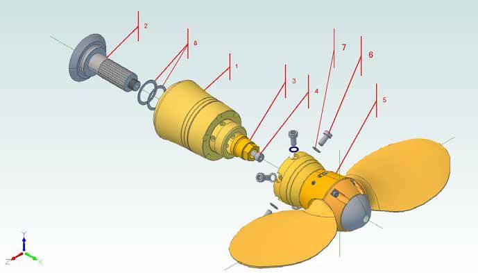
Installation on a Shaft Pitch Adjustment
»» mount the hub (1) on the shaft (2). Make sure the prop »» apply a small drop of loctite to the thread of the setscrew In general the pitch settings are done in the factory and are Possible reasons for pitch adjusting might be:
taper and keyway mate properly with shaft and key and (4) and tighten (20 Nm / 15 Ft.lb.). ready set for your boat and engine. Should it be necessary
»» If the engine does not reach the desired RPM
the top of the key does not touch the hub! File key if to adjust the pitch it is very simple on the VARIPROFILE,
»» align the blade assembly (5) with the boring and pivot reduce the forward pitch.
necessary. and can be done in or out of the water in a matter of few
pins and push onto the hub (1).
minutes. »» If the engine exceeds the desired RPM
»» Fit the counter screw (9) into the thread for the setscrew.
»» mount the socket screws (7) with washers (6) and tight- increase the forward pitch.
Pay attention not to set the prop nut with the counter
en (50 Nm / 37 Ft.lb). use loctite “medium” to secure the
screw! »» If the prop walk in astern is too strong
socket-screws (7).
reduce reverse pitch.
»» apply a small drop of loctite “medium” to the threads of Example below is showing a RH display
»» apply a small drop of loctite “low” to the threads of the
the nut (3) and tighten strongly 80 Nm / 60 Ft.lb), while Possible adjustment range see pitch sheet at page 6.
set screws (8) and tighten (10 Nm / 7 Ft.lb) LH lettering is marked to Detail “D” & “E”
blocking the hub with one hand against the counter
screw. »» check the function and see that the blade movement is
free.
»» after tightening the prop nut (3) remove the counter screw
(9) »» make sure you have a shaft anode with good contact to
the shaft.
2
1
8 Marked lettering of a LH Propeller
3 It is quite possible to set the pitch con-
5 tinuously variable and independently for
forward and reverse. The turning of the
adjusting screws (2) & (4) in Figure “Exam-
ple” by half a revolution changes the pitch
7 approx. 1“. That means a quarter turn (90°)
6 changes the pitch by ½” and a one full turn
4 by 2” etc. For a check of pitch adjustments
Möglich einstellbare Steigung there are markings on the hub rotating
1 siehe Tabelle S. 5! flange. To return to original factory pitch
9 settings, line up “V” resp. “R” markings on
Pay attention the hub face. (see example beside)
not to set the R= AS (Astern) V= AH (Ahead)
prop nut with the
counter screw
A. Adjusting the forward pitch: B. Adjusting the reverse pitch:
1. Remove the set screw (1) (3 mm allen key). 1. Remove the set screw (3) (3 mm allen key).
Under water: only 2 turns loosen. Under water: only 2 turns loosen.
3 2. Turn the adjusting screw (2) which is marked as 2. Turn the adjusting screw (4) which is marked as
“AH” or “V” with the 4 mm Allen-key as follows: “AS” or “R” with the 4 mm Allen-key as follows:
1. Hub 4. Set-Screw M8x12 (VP-64) 7. Socket Screws M8x25 (VP-64)
2a. Increasing of pitch: 2a. Increasing of pitch:
2. Shaft
or M8x16 (VP-76) or M10x30 (VP-76)
+ +
»» Turn the adjusting screw (2) clockwise. »» Turn the adjusting screw (4) anti-clockwise.
5. Blade assembly 8. Set-Screw M6x10 (VP-64)
3. Nut SW24 (VP-64) (see “NOTE” and page 8) (see “NOTE” and page 8)
or M8x12 (VP-76)
or SW30 (VP-76) 6. Washer ø10
»» Secure set screw (1) with LOCTITE low (pink) »» Secure set screw (3) with LOCTITE low (pink)
9. Counter Screw M8x120
Lock set screw (1) 3 Nm / 2 Ft.lb. Lock set screw (1) 3 Nm / 2 Ft.lb.
2b. Reducing of pitch: 2b. Reducing of pitch:
- -
»» Turn the adjusting screw (2) anti-clockwise. »» Turn the adjusting screw (4) clockwise.
(see “NOTE” and page 8) (see “NOTE” and page 8)
»» Secure set screw (1) with LOCTITE low (pink) »» Secure set screw (3) with LOCTITE low (pink).
Lock set screw (1) 3 Nm / 2 Ft.lb. Lock set screw (1) 3 Nm / 2 Ft.lb.
WARNING:
Engage forward/reverse at idling RPM`s only. Stop the engine immediately if any strange sounds or vibrations are
noticed coming from the propeller. Check that the propeller works in both forward and reverse before starting each
voyage. Do not start the the engine until the boat is in the water. Keep away from moving parts while handling the pro- NOTE: It is quite possible to set the pitch continuously variable and independently for forward and reverse. Turning
peller, the blades are like knives, and can cause considerable damage. Do not attempt to come close to the propeller of the adjusting screws (2) & (4) by half a revolution (180°) changes the pitch approx. 1“. This will change the engine
unless the engine is stopped. revolution by approx. 200.
4 5
Pitch adjustment table Operation & Servicing
The VARIPROFILE feathers automatically when the shaft rotation is stopped. After engine start-up and shifting into gear the
blades will engage in either forward or reverse.
THE BEST WAY TO FEATHER THE PROPELLER IN THE SAILPOSITION IS:
Prop.-ø pitch min. pitch max. Prop.-ø pitch min. pitch max.
tolerance:±0.3“ tolerance:±0.3“ tolerance:±0.3“ tolerance:±0.3“
13“ 7.5“ 12“ 13“ 7“ 12“ VARIPROFILE sailposition with VARIPROFILE sailposition with
mechanical gear-box: hydraulic transmission:
14“ 8“ 13“ 14“ 7.5“ 12.5“
2 blade 3 blade »» Power at 2 to 3 knots in forward. »» Power at 3 to 4 knots in forward.
15“ 9“ 14“ 15“ 8“ 13“
ahead ahead
16“ 9.5“ 15“ 16“ 9“ 14“ »» Stop the engine and engage the transmission in »» Stop the engine while still engaged in forward.
(V) (V)
VP-64 17“ 10“ 15.5“ 17“ 9.5“ 14.5“ reverse to stop the freewheeling of the shaft. The remaining oil pressure of the transmission
18“ 10.5“ 16“ 18“ 10“ 15“ will stop spinning the shaft to feather the blades
RH and LH in the sailposition.
13“ 7“ 12“ 13“ 6.5“ 11.5“
14“ 8“ 13“ 14“ 7“ 12“
2 blade 3 blade
15“ 9“ 14“ 15“ 8“ 13“
astern astern If the propeller is not feathered in the sailposition the shaft will freewheel like with a fixed propeller. In that case start the
16“ 10“ 15“ 16“ 9“ 14“
(R) (R) engine again and repeat the steps above. Once the prop is feathered , you may remain in gear or shift into neutral.
17“ 10.5“ 16.5“ 17“ 9.5“ 14.5“
18“ 11“ 17“ 18“ 10“ 15“ DO NOT stop the engine while it turns in reverse. In this case the blades will stay in the reverse position and will not feather.
You can actually use this feature to drive a shaft generator.
TROUBLE SHOOTING: If the propeller does not work in forward or reverse go systematically through the points below:
»» Check low idle of the engine. It should be 900 to 1000 positions for forward and reverse can be found in the
Prop.-ø pitch min. pitch max. Prop.-ø pitch min. pitch max. rpm in idle. owners manual of your transmission. A larger amount of
tolerance:±0.3“ tolerance:±0.3“ tolerance:±0.3“ tolerance:±0.3“ lever travel is in no way detrimental.
»» Check shifting movement of the transmission lever.
17“ 11“ 17“ 17“ 11.5“ 17“
Make sure that the shifting travel is not too short. The »» Check the clutch discs of the transmission. They could
18“ 11.5“ 18“ 18“ 12“ 18“ amount of lever travel, as measured at the pivot point of be worn out.
2 blade 3 blade
19“ 12.5“ 18“ 19“ 13“ 19“ the actuating lever, between the neutral position and end
ahead ahead
20“ 12.5“ 19“ 20“ 13“ 19“
(V) (V)
21“ 13“ 19“ 21“ 13.5“ 20“
VP-76 RH 22“ 14“ 20“ 22“ 14.5“ 21“ WARNING: It is important to follow the instructions below »» The propeller body must always be completely filled
17“ 9“ 15“ 17“ 10“ 16“ carefully so as to avoid excessive load and shock to the with a high viscosity grease. We recommend synthetic
gears, shortening their life. grease typ TW.2 GEL or mineral multi-purpose grease
18“ 10“ 16“ 18“ 10“ 16.5“
2 blade 3 blade EP/SAL
19“ 11“ 17.5“ 19“ 11“ 17“ »» When going from ahead to astern or the opposite, it is
astern astern necessary to idle down and shift at low rpm’s (max »» The propeller must be protected from electrolytic cor-
20“ 11“ 17.5“ 20“ 12“ 18“
(R) (R) .1200rpm) between gears to allow smooth reversing of rosion by fitting the usual zinc anodes on the shaft plus
21“ 12“ 18.5“ 21“ 13“ 19“
rotation without binding. This will substantially length- the prop anode. We recommend the replacement of the
22“ 13“ 19.5“ 22“ 14“ 20“ en the service life of your propeller gears. anode once a year.
»» When going from ahead to astern or the opposite, you »» If you want to protect your VARIPROFILE with Antifoul-
can hear the turning-noise of the feathering blades. ing, use only Antifouling which needs a primer first.
This is normal and not a problem or a defect of your Otherwise chemical interaction and decomposition
Prop.-ø pitch min. pitch max. Prop.-ø pitch min. pitch max. VARIPROFILE. could occur. Our recommendation is Velox TF plus
tolerance:±0.3“ tolerance:±0.3“ tolerance:±0.3“ tolerance:±0.3“ including a primer ( offers also protection against elec-
17“ 10.5“ 17“ 17“ 11.5“ 17“ trolyses ), available from your VARIPROFILE distributor.
18“ 11.5“ 18“ 18“ 12“ 18“
2 blade 3 blade
19“ 11.5“ 18“ 19“ 13“ 19“
ahead ahead SERVICING
20“ 12“ 19“ 20“ 13“ 19“
(V) (V)
21“ 12.5“ 19“ 21“ 13.5“ 20“ The VARIPROFILE needs to be greased a minimum of once a year with the
22“ 13“ 19“ 22“ 14.5“ 20“ special EP/SAL lubricant available from your VARIPROFILE dealer. The VARIPRO-
VP-76 LH FILE body should always be completely filled with a high viscosity grease of a
17“ 8“ 14.5“ 17“ 8“ 14“ hydrophobic nature. Remove the cap screw and screw in the lubricating nipple
18“ 9“ 15“ 18“ 9“ 15“ which is supplied with the tools. Further remove the zinc anode! With each pump
2 blade 3 blade of the grease gun rotate the propeller from forward stop to reverse stop to allow
19“ 10“ 16“ 19“ 10“ 16.5“
astern astern the grease to work through the propeller. Stop to pump when enough grease
20“ 10“ 16.5“ 20“ 11“ 17“
(R) (R) comes out of the anode drill hole on top of the prop (Fig.1).
21“ 11“ 17“ 21“ 12“ 18“
22“ 12“ 18“ 22“ 12“ 18“ Factory supplied special grease EP/SAL is recommended and available from
your VARIPROFILE distributor. Avoid regular white grease (sterntube-grease ) !
Never dismantle the VARIPROFILE yourself!
Disassembly and reassembly require special tools and technical know-how only available at the factory
or their approved service centres.
6 7
Pitch adjustment table Operation & Servicing
The VARIPROFILE feathers automatically when the shaft rotation is stopped. After engine start-up and shifting into gear the
blades will engage in either forward or reverse.
THE BEST WAY TO FEATHER THE PROPELLER IN THE SAILPOSITION IS:
Prop.-ø pitch min. pitch max. Prop.-ø pitch min. pitch max.
tolerance:±0.3“ tolerance:±0.3“ tolerance:±0.3“ tolerance:±0.3“
13“ 7.5“ 12“ 13“ 7“ 12“ VARIPROFILE sailposition with VARIPROFILE sailposition with
mechanical gear-box: hydraulic transmission:
14“ 8“ 13“ 14“ 7.5“ 12.5“
2 blade 3 blade »» Power at 2 to 3 knots in forward. »» Power at 3 to 4 knots in forward.
15“ 9“ 14“ 15“ 8“ 13“
ahead ahead
16“ 9.5“ 15“ 16“ 9“ 14“ »» Stop the engine and engage the transmission in »» Stop the engine while still engaged in forward.
(V) (V)
VP-64 17“ 10“ 15.5“ 17“ 9.5“ 14.5“ reverse to stop the freewheeling of the shaft. The remaining oil pressure of the transmission
18“ 10.5“ 16“ 18“ 10“ 15“ will stop spinning the shaft to feather the blades
RH and LH in the sailposition.
13“ 7“ 12“ 13“ 6.5“ 11.5“
14“ 8“ 13“ 14“ 7“ 12“
2 blade 3 blade
15“ 9“ 14“ 15“ 8“ 13“
astern astern If the propeller is not feathered in the sailposition the shaft will freewheel like with a fixed propeller. In that case start the
16“ 10“ 15“ 16“ 9“ 14“
(R) (R) engine again and repeat the steps above. Once the prop is feathered , you may remain in gear or shift into neutral.
17“ 10.5“ 16.5“ 17“ 9.5“ 14.5“
18“ 11“ 17“ 18“ 10“ 15“ DO NOT stop the engine while it turns in reverse. In this case the blades will stay in the reverse position and will not feather.
You can actually use this feature to drive a shaft generator.
TROUBLE SHOOTING: If the propeller does not work in forward or reverse go systematically through the points below:
»» Check low idle of the engine. It should be 900 to 1000 positions for forward and reverse can be found in the
Prop.-ø pitch min. pitch max. Prop.-ø pitch min. pitch max. rpm in idle. owners manual of your transmission. A larger amount of
tolerance:±0.3“ tolerance:±0.3“ tolerance:±0.3“ tolerance:±0.3“ lever travel is in no way detrimental.
»» Check shifting movement of the transmission lever.
17“ 11“ 17“ 17“ 11.5“ 17“
Make sure that the shifting travel is not too short. The »» Check the clutch discs of the transmission. They could
18“ 11.5“ 18“ 18“ 12“ 18“ amount of lever travel, as measured at the pivot point of be worn out.
2 blade 3 blade
19“ 12.5“ 18“ 19“ 13“ 19“ the actuating lever, between the neutral position and end
ahead ahead
20“ 12.5“ 19“ 20“ 13“ 19“
(V) (V)
21“ 13“ 19“ 21“ 13.5“ 20“
VP-76 RH 22“ 14“ 20“ 22“ 14.5“ 21“ WARNING: It is important to follow the instructions below »» The propeller body must always be completely filled
17“ 9“ 15“ 17“ 10“ 16“ carefully so as to avoid excessive load and shock to the with a high viscosity grease. We recommend synthetic
gears, shortening their life. grease typ TW.2 GEL or mineral multi-purpose grease
18“ 10“ 16“ 18“ 10“ 16.5“
2 blade 3 blade EP/SAL
19“ 11“ 17.5“ 19“ 11“ 17“ »» When going from ahead to astern or the opposite, it is
astern astern necessary to idle down and shift at low rpm’s (max »» The propeller must be protected from electrolytic cor-
20“ 11“ 17.5“ 20“ 12“ 18“
(R) (R) .1200rpm) between gears to allow smooth reversing of rosion by fitting the usual zinc anodes on the shaft plus
21“ 12“ 18.5“ 21“ 13“ 19“
rotation without binding. This will substantially length- the prop anode. We recommend the replacement of the
22“ 13“ 19.5“ 22“ 14“ 20“ en the service life of your propeller gears. anode once a year.
»» When going from ahead to astern or the opposite, you »» If you want to protect your VARIPROFILE with Antifoul-
can hear the turning-noise of the feathering blades. ing, use only Antifouling which needs a primer first.
This is normal and not a problem or a defect of your Otherwise chemical interaction and decomposition
Prop.-ø pitch min. pitch max. Prop.-ø pitch min. pitch max. VARIPROFILE. could occur. Our recommendation is Velox TF plus
tolerance:±0.3“ tolerance:±0.3“ tolerance:±0.3“ tolerance:±0.3“ including a primer ( offers also protection against elec-
17“ 10.5“ 17“ 17“ 11.5“ 17“ trolyses ), available from your VARIPROFILE distributor.
18“ 11.5“ 18“ 18“ 12“ 18“
2 blade 3 blade
19“ 11.5“ 18“ 19“ 13“ 19“
ahead ahead SERVICING
20“ 12“ 19“ 20“ 13“ 19“
(V) (V)
21“ 12.5“ 19“ 21“ 13.5“ 20“ The VARIPROFILE needs to be greased a minimum of once a year with the
22“ 13“ 19“ 22“ 14.5“ 20“ special EP/SAL lubricant available from your VARIPROFILE dealer. The VARIPRO-
VP-76 LH FILE body should always be completely filled with a high viscosity grease of a
17“ 8“ 14.5“ 17“ 8“ 14“ hydrophobic nature. Remove the cap screw and screw in the lubricating nipple
18“ 9“ 15“ 18“ 9“ 15“ which is supplied with the tools. Further remove the zinc anode! With each pump
2 blade 3 blade of the grease gun rotate the propeller from forward stop to reverse stop to allow
19“ 10“ 16“ 19“ 10“ 16.5“
astern astern the grease to work through the propeller. Stop to pump when enough grease
20“ 10“ 16.5“ 20“ 11“ 17“
(R) (R) comes out of the anode drill hole on top of the prop (Fig.1).
21“ 11“ 17“ 21“ 12“ 18“
22“ 12“ 18“ 22“ 12“ 18“ Factory supplied special grease EP/SAL is recommended and available from
your VARIPROFILE distributor. Avoid regular white grease (sterntube-grease ) !
Never dismantle the VARIPROFILE yourself!
Disassembly and reassembly require special tools and technical know-how only available at the factory
or their approved service centres.
6 7Removal instructions Torque settings for the prop-nut
DO NOT DISMANTLE THE PROPELLER UNIT (5)! Standard – thread Fine – thread
»» Remove the blade assembly (5) from the hub (1). »» now remove the prop nut (3) while blocking the hub with M 14 x 2 40 Nm M 14 x 1,5 40 Nm
one hand against the counter screw. UNC 1/2 “-13 30 ft/lb BSF 1/2 “- 16 30 ft/lb
»» Therefore remove first the 3 off Set-Screws (8).
»» align the puller with the socket screws (7) of the hub (1)
»» Now you can remove the Socket Screws (7). Take care M 16 x 2 60 Nm M 16 x 1,5 70 Nm
and tighten (20 Nm / 15 Ft.lb).
that the prop will not fall off after removing all Socket BSW 5 / 8 “ – 11 45 ft/lb BSF 5 / 8 “ – 14 50 ft/lb
Screws! »» do not tighten the set screws (8)! UNC 5 / 8 “ - 11 UNC 5 / 8 “ - 18
»» Dismount the blade assembly (5) from the hub (1). »» tighten the extractor screw clockwise strongly, while hold- M 16 x 2 60 Nm / M 20 x 1,5 135 Nm
ing by hand the counter screw (9). Yanmar Saildrive 45 ft/lb BSF 3 / 4 “ – 12 100 ft/lb
»» Remove the Set-Screw (4) completely and screw into the
same hole (M8) the Counter Screw (9). Pay attention not »» you can now remove the hub from the shaft. SD 20 & SD 31 UNC 3 / 4 “ - 16
to set the prop nut with the counter screw!
M 20 x 2,5 125 Nm M 20 x 2 100 Nm /
BSW 3 / 4 “ – 10 / 95 ft/lb Yanmar Saildrive 75 ft/lb
UNC 3 / 4 “ - 10 SD 40 & SD 50
2
UNC 7 / 8 “-9 160 Nm M 24 x 2 225 Nm
1 115 ft/lb BSF 1 “ - 10 165 ft/lb
8 UNF 1 “ - 12
3
M 24 x 3 210 Nm M 30 x 2 430 Nm
5 BSW 1 “ - 8 155 ft/lb 315 ft/lb
UNC 1 “ - 8
M 27 x 3 315Nm
230 ft/lb
7
6
4 M 30 x 3,5 350 Nm
UNC 1 1/8” - 7 255 ft/lb
1
9
Pay attention
not to set the
prop nut with the
counter screw
3
1. Hub 4. Set-Screw M8x12 (VP-64) 7. Socket Screws M8x25 (VP-64)
or M8x16 (VP-76) or M10x30 (VP-76)
2. Shaft
5. Blade assembly 8. Set-Screw M6x10 (VP-64)
3. Nut SW24 (VP-64)
or M8x12 (VP-76)
or SW30 (VP-76) 6. Washer ø10
9. Counter Screw M8x120
It is recommended to only use the special puller available from your VARIPROFILE dealer.
SUBJECT TO TECHNICAL ALTERATIONS; ERRORS and MISPRINTS
8 9Removal instructions Torque settings for the prop-nut
DO NOT DISMANTLE THE PROPELLER UNIT (5)! Standard – thread Fine – thread
»» Remove the blade assembly (5) from the hub (1). »» now remove the prop nut (3) while blocking the hub with M 14 x 2 40 Nm M 14 x 1,5 40 Nm
one hand against the counter screw. UNC 1/2 “-13 30 ft/lb BSF 1/2 “- 16 30 ft/lb
»» Therefore remove first the 3 off Set-Screws (8).
»» align the puller with the socket screws (7) of the hub (1)
»» Now you can remove the Socket Screws (7). Take care M 16 x 2 60 Nm M 16 x 1,5 70 Nm
and tighten (20 Nm / 15 Ft.lb).
that the prop will not fall off after removing all Socket BSW 5 / 8 “ – 11 45 ft/lb BSF 5 / 8 “ – 14 50 ft/lb
Screws! »» do not tighten the set screws (8)! UNC 5 / 8 “ - 11 UNC 5 / 8 “ - 18
»» Dismount the blade assembly (5) from the hub (1). »» tighten the extractor screw clockwise strongly, while hold- M 16 x 2 60 Nm / M 20 x 1,5 135 Nm
ing by hand the counter screw (9). Yanmar Saildrive 45 ft/lb BSF 3 / 4 “ – 12 100 ft/lb
»» Remove the Set-Screw (4) completely and screw into the
same hole (M8) the Counter Screw (9). Pay attention not »» you can now remove the hub from the shaft. SD 20 & SD 31 UNC 3 / 4 “ - 16
to set the prop nut with the counter screw!
M 20 x 2,5 125 Nm M 20 x 2 100 Nm /
BSW 3 / 4 “ – 10 / 95 ft/lb Yanmar Saildrive 75 ft/lb
UNC 3 / 4 “ - 10 SD 40 & SD 50
2
UNC 7 / 8 “-9 160 Nm M 24 x 2 225 Nm
1 115 ft/lb BSF 1 “ - 10 165 ft/lb
8 UNF 1 “ - 12
3
M 24 x 3 210 Nm M 30 x 2 430 Nm
5 BSW 1 “ - 8 155 ft/lb 315 ft/lb
UNC 1 “ - 8
M 27 x 3 315Nm
230 ft/lb
7
6
4 M 30 x 3,5 350 Nm
UNC 1 1/8” - 7 255 ft/lb
1
9
Pay attention
not to set the
prop nut with the
counter screw
3
1. Hub 4. Set-Screw M8x12 (VP-64) 7. Socket Screws M8x25 (VP-64)
or M8x16 (VP-76) or M10x30 (VP-76)
2. Shaft
5. Blade assembly 8. Set-Screw M6x10 (VP-64)
3. Nut SW24 (VP-64)
or M8x12 (VP-76)
or SW30 (VP-76) 6. Washer ø10
9. Counter Screw M8x120
It is recommended to only use the special puller available from your VARIPROFILE dealer.
SUBJECT TO TECHNICAL ALTERATIONS; ERRORS and MISPRINTS
8 9Certificate No:
TAM000017G
TYPE APPROVAL CERTIFICATE
This is to certify:
That the Controllable Pitch Propeller
with type designation(s)
Feathering Propeller series VP, GP, DF
Issued to
S.P.W. GmbH Sail Propeller- und Wellenbau
Bremerhaven, Germany
is found to comply with
DNV GL rules for classification – Ships
DNV GL rules for classification – Yachts
DNV GL rules for classification – High speed and light craft
Application :
Product(s) approved by this certificate is/are accepted for installation on all vessels classed
by DNV GL.
Issued at Hamburg on 2021-02-16
for DNV GL
This Certificate is valid until 2026-02-15.
DNV GL local station: Hamburg – CMC North/East
Approval Engineer: Olaf Richter Olaf Drews
Head of Section
This Certificate is subject to terms and conditions overleaf. Any significant change in design or construction may render this Certificate invalid.
The validity date relates to the Type Approval Certificate and not to the approval of equipment/systems installed.
LEGAL DISCLAIMER: Unless otherwise stated in the applicable contract with the holder of this document, or following from mandatory law, the
liability of DNV GL AS, its parent companies and subsidiaries as well as their officers, directors and employees (“DNV GL”) arising from or in
connection with the services rendered for the purpose of the issuance of this document or reliance thereon, whether in contract or in tort
(including negligence), shall be limited to direct losses and under any circumstance be limited to 300,000 USD.
Form code: TA 251 Revision: 2020-02 www.dnvgl.com Page 1 of 4
© DNV GL 2014. DNV GL and the Horizon Graphic are trademarks of DNV GL AS.
10Job Id: 262.1-034406-1
Certificate No: TAM000017G
Product description
Feathering propellers
Application/Limitation
For sailing ship propulsion.
Type Blades Propeller Engine Propeller Propeller
diameter power torque speed
max. [mm] max. [kW] max. [Nm] max. [rpm]
VP-64 2, 3 455 22 150 1400
VP-76 2, 3 560 55 375 1400
VP-104 3 660 82 653 1200
DF-80, GP-80 2, 3, 4 432 22 150 1400
DF-107, GP-107 2, 3, 4 508 59 402 1400
DF-112, GP-112 3, 4 635 88 700 1200
DF-128 3, 4 715 103 894 1100
DF-140 3, 4 762 132 1261 1000
DF-160 3 864 202 2030 950
DF-180 3 914 257 2727 900
DF-190 4 864 202 2030 950
DF-210 4 914 257 2727 900
DF-230 3 1016 308 3676 800
DF-260 4 1016 308 3676 800
DF-280 3 1270 404 5144 750
DF-310 4 1270 404 5144 750
DF-380 4 1575 550 12500 750
Type Approval documentation
Drw No Rev Title Status
- 2020-11-21 Drawing list VP64 DI Discarded**
- 2020-11-21 Drawing list GP112 DI Discarded**
- 2010-01-19 Document List of VariProfile DI Discarded**
- - DF-380 part list DI Discarded**
- - Material data propeller hub FI For Inf.
- - Propeller assembly DI Discarded**
- - Variprofile Broschüre DI Discarded**
- 2020-11-21 Drawing list VP76 DI Discarded**
- - Blade sections DF-xx 12-50" AP Approved
- - Variprop brochure DI Discarded**
- - Assembly drawings + blade sections DF-xx AP Approved
Anode DF-380 01 Anode DF-380 DI Discarded**
Anode VP104-02 01 Anode VP-104 DI Discarded**
Anode VP64-02 04 Anode / VP-64 DI Discarded**
Anode VP76-02 02 Anode / VP-76 DI Discarded**
Anschlag 104-RH-04 06 Anschlag VP-104 3 Blatt AP Approved
Anschlag VP64-04 08 Anschlag VP-64 AP Approved
Anschlag VP76-04 06 Anschlag v2.1 VP-76 AP Approved
Assembly DF-380-4bl-00 00 Assembly DF-380 AP Approved
Form code: TA 251 Revision: 2020-02 www.dnvgl.com Page 2 of 4
11Job Id: 262.1-034406-1
Certificate No: TAM000017G
Assembly Exploded_VP76-2bl-04 06 Assembly VP-76 v3.0/GL AP Approved
Assembly FlgDF-380-50-00 00 Flügel DF-380 FI For Inf.
Assembly_Exploded VP-104-3bl-03 03 Assembly VP-104 AP Approved
Assembly_Exploded-GP-107-3bl - Assembly_Exploded GP-107-3blade-19 AP Approved
Assembly_VP64-04_exploded-01 12 Assembly VP-64 v3.0/GL AP Approved
Assembly-1 DF-380-50-00 sh.1 00 Assembly DF-380 AP Approved
Assembly-2 DF-380-50-00 sh.2 00 Assembly DF-380 AP Approved
Assembly-3 DF-380-50-00 sh.3 00 Assembly DF-380 AP Approved
Assembly-GP-80-3bl - Assembly_Exploded-GP-80-3bl AP Approved
Connect-plate-05 07a Connecting Plate v3.0/GL VP-64 AP Approved
Connect-plate-VP104-04 04/GL Connecting Plate VP-104 AP Approved
Connect-plate-VP76-05 07a Connecting plate v3.0/GL VP-76 AP Approved
DF380_Flg-62-00-flat 2008-07-09 DF380_Flg-62-00 VariProp symm. section AP Approved
DIN 913 - M30 x 120 00 Steigungsverstellschraube DF-380 FI For Inf.
FlgDF_schnitt-380-62-00 - Flügelschnitt DF-380/48-62" AP Approved
FlgDF-80GP-16 01 Flügel DF-80&107-GP/Serie AP Approved
FlgGP-112-20-06a-flat 01 Flügel DF-112SE Vers.GP AP Approved
FlgGP-112-20-06a-flat - Flügel DF-112_GP AP Approved
FlgSchnitt-GP-112-20_24-01 2020-02-13 Flügelkontur DF-112 / dia. 20-24" AP Approved
FlgVerzGP-112-01 01 Flügel-Zahnrad GP-112 AP Approved
Flg-VP104-Schnitt-26-00 00 Flügelschnitt VP-104 26" AP Approved
Flg-VP104-Schnitt-26-01 00 Flügelschnitt VP-104 26" AP Approved
GearAc_1818-04aRH 07 Nabenverzahnung VP-64 v3.0/GL AP Approved
GearAc_2424-04RH 04 Nabenverzahnung VP-76 v3.0 AP Approved
GearAc_2727-03RH 03 Nabenverzahnung VP-104 AP Approved
GearPas_1818-02aLH 06 Flügelverzahnung VP-64 v3.0/GL AP Approved
GearPas_2424-03LH 05 Flügelverzahnung VP-76 v3.0 AP Approved
GearPas_2727-01LH 03a Flügelverzahnung VP-104 AP Approved
Geob104-3bl-00 01 VP-104 3 Blatt Gehäuse Oberteil AP Approved
Geob112_GP-3bl 00 DF-112_GP 3 Blatt Gehäuse Oberteil AP Approved
Geob112_GP-4bl 00 DF-112_GP 4 Blatt Gehäuse Oberteil AP Approved
Geob380-4bl-01 01 Gehäuse-Oberteil 4 Blatt DF-380 AP Approved
Geob64-2bl-02 06 VP-64 2 Blatt Gehäuse Oberteil AP Approved
Geob64-3bl-02 07 VP-64 3 Blatt Gehäuse Oberteil AP Approved
Geob76-2bl-01 07 VP-76 2 Blatt Gehäuse Oberteil AP Approved
Geob76-3bl-01 05 VP-76 3 Blatt Gehäuse Oberteil AP Approved
Geut104-3bl-02 03 VP-104 3 Blatt Gehäuse Unterteil AP Approved
Geut112_GP-3bl 00 DF-112_GP 3 Blatt Gehäuse Unterteil AP Approved
Geut112_GP-4bl 00 DF-112_GP 4 Blatt Gehäuse Unterteil AP Approved
Geut112_SD-4bl 00 DF-112_SD 4 Blatt Gehäuse Unterteil SD AP Approved
Geut112-3bl 01a DF-112_GP/SD 3 Blatt Gehäuse Untert. SD AP Approved
Geut380-4bl-Sundin 01 Gehäuse-Unterteil 4 Blatt DF-380 AP Approved
Geut64-2bl-01 06a VP-64 2 Blatt Gehäuse Unterteil AP Approved
Geut64-3bl-01 07a VP-64 3 Blatt Gehäuse Unterteil AP Approved
Geut76-2bl-01 06a VP-76 2 Blatt Gehäuse Unterteil AP Approved
Geut76-3bl-01 05a VP-76 3 Blatt Gehäuse Unterteil AP Approved
GP112-20_24-01 2020-02-13 Flügelkontur DF-112 / dia. 20-24" AP Approved
GP112-20-06a_DNV 01 Assembly_Exploded_GP-112-3bl AP Approved
GP112-24-01 2020-11-19 Flügelkontur DF-112 / dia. 24" AP Approved
Hub-25_VP64-04a 06a Hub-25 VP-64 AP Approved
Form code: TA 251 Revision: 2020-02 www.dnvgl.com Page 3 of 4
12Job Id: 262.1-034406-1
Certificate No: TAM000017G
Hub-30_VP64-03 05a Hub-30 VP-64 AP Approved
Hub-30_VP76-02 04a Hub-30 VP-76 AP Approved
Hub-45_VP104-02 02/GL Hub-45 VP-104 AP Approved
Kappe DF-380-00 01 Kappe DF-380 FI For Inf.
Nabe DF-380-01 01 Nabe DF-380 AP Approved
NabeDF112-02 04 Nabe DF-112 AP Approved
PropNut DF-380-00 00 Prop.-Nut DF-380 FI For Inf.
Puller DF-380-00 00 Abzieher f. DF-380 DI Discarded**
VP104_Flg-20-01_flat 2009-02-11 Blade VP-104 20" AP Approved
VP104_Flg-26-01_flat 2009-04-15 Blade VP-104 26" AP Approved
VP64_Flg-13-03_flat 2008-05-16 Blade VP-64 13" AP Approved
VP64_Flg-18-03_flat 2008-05-16 Blade VP-64 18" AP Approved
VP76_Flg-17-01_flat 2008-06-10 Blade VP-76 17" AP Approved
VP76_Flg-22-01_flat 2008-06-25 Blade VP-76 22" AP Approved
Tests carried out
None.
Marking of product
Manufacturer’s name or trademark. Type number designation.
Periodical assessment
For retention of the Type Approval, a DNV GL surveyor shall perform an assessment after 2 years and
after 3.5 years to verify that the conditions of the type approval are complied with. A renewal
assessment will be performed at renewal of the certificate.
The objective of the Periodical Assessment is to verify that the conditions for the Type Approval are not
altered since the Type Approval Certificate was issued. The main scope of the Periodical Assessment will
normally include:
Verification of the Type Approval applicant’s production and quality system w.r.t. ensuring
continued consistent production of the Type Approved products at the Type Approval applicant’s
own premises and at other companies that are given the responsibility for manufacturing of the
products
Review of the Type Approval documentation and that this is still used as basis for the production
Review of possible changes to the design, the material and the performance of the product
Verification of the product marking
In cases where the Type Approved product is manufactured at other companies, the Periodical
Assessment shall verify that the Type Approval applicant has a quality control system for consistent
production at their licensees/subcontractors. Furthermore Periodical Assessment shall be carried out
randomly at these companies.
When a Type Approved product is manufactured at other companies, the Type Approval applicant takes
the sole responsibility for the conformity of the product to the applicable requirements.
END OF CERTIFICATE.
Form code: TA 251 Revision: 2020-02 www.dnvgl.com Page 4 of 4
13Notes Notes
14 11Notes Notes 10 15
Die VARI-Family

             drehflügelpropeller
                                                           ®

                                                               FA LT P R O P E L L E R
                                    Drehflügelpropeller

             drehflügelpropeller
                                                               FA LT P R O P E L L E R

                                                           ®

             Feathering Propeller   Feathering Propeller       Folding Propeller

            For further informations visit
            www.variprofile.com

TAM000017G                     Online-Shop

                                                                                         made by
Westkai 58, 27572 Bremerhaven
Telefon +49 (0)471 / 7 70 47
Telefax +49 (0)471 / 7 74 44
info@spw-gmbh.de, www.spw-gmbh.de
You can also read