Accessories & Maintenance parts 2013 - DBMoteurs
←
→
Page content transcription
If your browser does not render page correctly, please read the page content below

Accessories &       2013
Maintenance parts

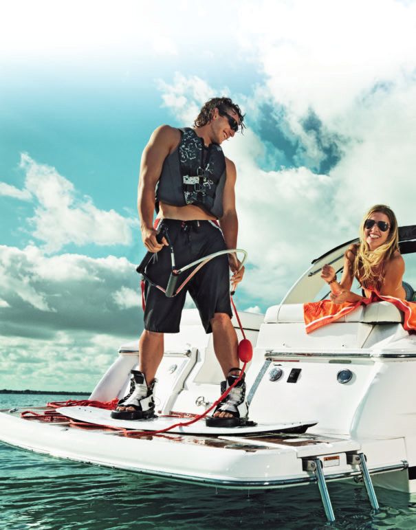
At Volvo Penta, we consider you, the owner of a Volvo Penta engine, extremely valued. Boating should be fun and you should not
have to worry about anything clouding your day out. Using Volvo Penta genuine parts and service from our authorized Volvo Penta
dealers worldwide, should ensure the high performance and reliability of your Volvo Penta engine.

Amongst the new items in this catalogue are a new range of steering wheels and a range of additional EVC options. We would also
like you to take a closer look at our line cutter, eliminate the worry of getting lines and ropes tangled up in your IPS propeller. We
also hope that you like the new look of this year's catalogue!

In this catalogue you will find the parts and accessories to customize your Volvo Penta engine and boat. There is more information
about our products to be found on our website, volvopenta.com and volvopentashop.com, or visit your local dealer.

Welcome aboard!

Kenneth Norlén
Head of Global Aftermarket
AB Volvo Penta

2
Genuine
NEWS 4
EVC 6
Volvo Penta
Controls 7
EVC options 8
EVC full control 9
Instruments 10
Parts and MECHANICALLY OPERATED
CONTROLS & INSTRUMENTS 14
Accessories Mechanically operated controls
Analogue instruments
STEERING
15
21
28
When using Genuine Volvo Penta Parts and Accessories you
are assured that you will maintain and optimize your Volvo BOAT TRIM SYSTEM 31
Penta product to the highest quality standard.
ENGINE ACCESSORIES 32
Our core values – Quality, Safety and Environmental Care –
Fuel supply 33
are always built-in to each component. We design, test, de-
velop and manufacture our genuine parts and accessories to Exhaust 38
the same quality level as we do with our engines. In this way Chemicals 41
you get high quality products with a warranty that you can rely Cooling system 46
on. Each component is original and made to match.
Power takeoff 51
At your Volvo Penta Dealer you will find specially trained Electrical supply 52
mechanics that will handle and fit the components correctly Transmission 54
onto your Volvo Penta product. More than this, you get one
contact for everything. Volvo Penta dealers also handle PROPELLERS 60
service, maintenance, support and warranties for all Volvo
Duoprop propellers for Aquamatic 61
Penta products.
Single propellers for Aquamatic 66
Propellers for Volvo Penta IPS 68
Folding propellers for saildrive and shaft 70
Fixed propellers for saildrive 74
Anodes 75
SAFETY & COMFORT 76
Bilge pumps 77
Flexi pumps 80
Air heater 81
Sound absorbent panels 82
EXCHANGE SYSTEM 83
MAINTENANCE PARTS 84
Diesel engines 84
Petrol engines 86
Drives 89
3
NEWS
For us, world-class product development is a fundamental, never-ending process. Being part of the Volvo Group gives a wide
scope when it comes to innovative thinking. Our new products focus on you and on improving your everyday boating experience.

New steering wheels                              Vacuum valve                                    Line Cutter
Take a look at the new Volvo Penta range of      Made of Polypropylene Moplen plastic and is     The Volvo Penta line cutter is an easy to install
exclusive and ergonomic steering wheels. They    available for D1 and D2 installations.          accessory that provides additional protection in
combine high-quality materials with a design                                                     waters where it may be required. It is designed
                                                 The range features four different models: 16,
perfectly matched to Volvo Penta’s range of                                                      to cut through ropes, fishing lines, plastic bags
                                                 19, 22 and 25 mm hose connections
controls and displays. The new steering wheels                                                   and nets before they can enter between the
will be available spring 2013.                                                                   propellers and possibly cause damage to the
                                                                                                 propeller shaft sealing. The line cutter is available
                                                                                                 for all Volvo Penta IPS models.

page 28                                          page 46                                         page 68

4    NEWS
For more information about
our latest news please go to
www.volvopenta.com/leaflets
or use the QR code
Joystick driving & AUTOPILOT The IH-series
A whole new way to manoeuvre your boat with precision at all speeds. Introducing a new series of propellers, enjoy better grip when accelerating
You steer comfortably by pushing and rotating the joystick. The and turning.
integrated autopilot supports by automatically engaging after every
Enjoy the comfort of a well-balanced propeller giving a vibration-free
course change. A smart, new option for intuitive driving.
ride.
page 8 page 65
NEWS 5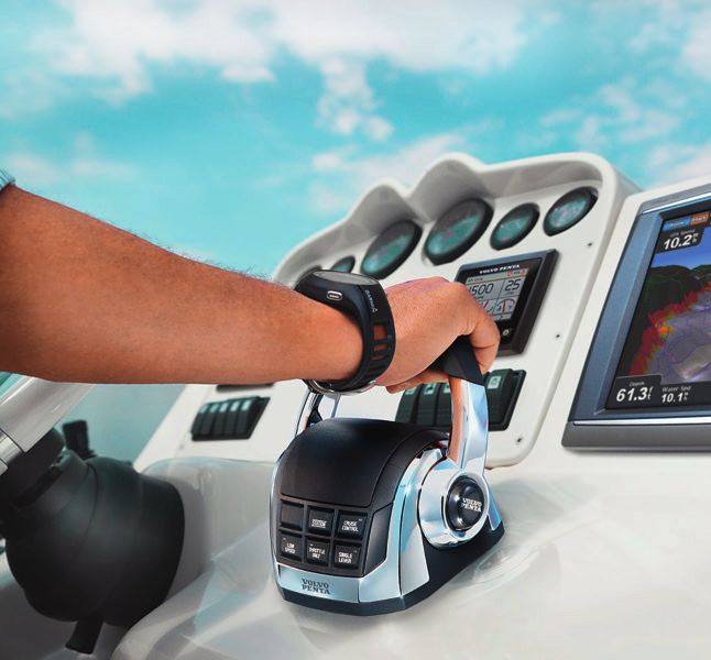
EVC
EVC – Electronic Vessel Control – is Volvo Penta’s common         Controls
electronic platform for controlling engine and transmission and   Volvo Pentas wide range of ergonomically, solid and smart EVC
integrating all driver information. EVC is based on CAN-bus       controls.
technology and lets engine, drives, controls and instruments
quickly exchange information. It constantly supervises all        Instruments
important functions and takes precautionary measures if need-     Multi-information displays and round EVC instruments with all
ed, always keeping you updated in an intuitive way. All elec-     the information that you want.
tronic units have composite casing and the connectors are of
heavy-duty quality.                                               Please contact your local Volvo Penta dealer to determine your
                                                                  EVC generation. Use our matchlists to know what controls,
Furthermore, EVC also opens up a lot of possibilities when it     instruments and software that complies with your EVC generation.
comes to installing new, previously unthinkable, hardware and
software features. Joystick driving and docking, Low-speed        Read more at www.volvopenta.com/matchlist
mode, Powertrim assistant and more – are all based on the
intelligence of EVC.

6    Electronic Vessel Control
CONTROLS
                                                                                             The line-up of EVC controls features something for every
                                                                                             taste. All features are chosen and designed to offer the
                                                                                             best level of safety and comfort. All Volvo Penta controls are
                                                                                             ergonomic and have a solid feel to them. The EVC controls
                                                                                             are developed together with the EVC system for maximum
                                                                                             reliability.
                                                                                             In line with Volvo Penta’s “Easier boating” concept, a number
                                                                                             of functions have been built into the new controls. The con-
                                                                                             trols comes with:
                                                                                             • Station on/off function
                                                                                             • Throttle only function

                                                                                             Push-buttons for EVC options such as:
                                                                                             • Low-speed mode
                                                                                             • Single-lever mode
                                                                                             • Cruise control

                              IPS                                 Diesel Inboard                                             Aquamatic Sterndrive

                   Twin*              Joystick      Twin             Single             Single              Twin             Single        Single       Joystick
 EVC-E          21730162            21846873      21730162         21730161            21856291           21730160          21730157      21847446     21846873
 EVC-D          21730162            21846873      21730162         21730161            21856291           21730160          21730157      21847446     21846873

*Also for triple and quadruple installations.

                                IPS                                    Diesel Inboard                                           Aquamatic Sterndrive

                    Twin*                 Twin*            Twin               Twin                                   Twin                Twin
 EVC-C           21164033              21164029      21164033             21164029                                 21164033            21164029
 EVC-B           21164033              21164029      21164033             21164029                                 21164033            21164029
 EVC-A           21164033              21164029      21164033             21164029                                 21164033            21164029

                 Joystick**                            Single                 Single             Single             Single              Single          Single
 EVC-C           21846873                            21164031             21164027           3847394               21164031            21164027        3847394
 EVC-B           21846873                            21164031             21164027           3847394               21164031            21164027        3847394
 EVC-A           21846873                            21164031             21164027           3847394               21164031            21164027        3847394

*Also for triple and quadruple installations.
** Replaces the old Joystick.
                                                                                                          Electronic Vessel Control - Controls                     7
Joystick Docking
EVC Options                                                                      The skipper’s best friend that makes docking
                                                                                 easy, even fun. Intuitive, one-hand manoeuvring
The EVC system opens up a world of new opportunities that
                                                                                 in close quarters.
make driving, safer and more fun. The following options are
available for our EVC engines.
Use our matchlists to know what options are available for                        Joystick driving & AUTOPILOT
you EVC engine: www.volvopenta.com/matchlist
                                                                           NEW   A whole new way to manoeuvre your boat with
                                                                                 precision at all speeds. You steer comfortably
                                                                                 by pushing and rotating the joystick. The in-
                                                                                 tegrated autopilot supports by automatically
                                                                                 engaging after every course change. A smart,
                                                                                 new option for intuitive driving.

                                                                                 Dynamic Positioning system
                                                                                 The Dynamic Positioning System lets you
                                                                                 practically freeze your boat’s position and head-
                                                                                 ing – the perfect feature when preparing for
                                                                                 docking or waiting for refueling.

                                                                                 Powertrim Assistant
                                                                                 Automatically gives you the best possible drive
                                                                                 trim. The result is a perfect running attitude for
                                                                                 optimum performance and low fuel consumption.

                                                                                 Low-speed mode
                                                                                 Reduces boat speed at idling by 50 % from 5–6
                               Volvo Penta          Aquamatic    Inboard
                                                                                 knots to 2–3 knots. Integrated in the control
                               IPS                  Sterndrive
                                                                                 and perfect when driving in marinas and canals.
 Joystick Docking                                       1)
                                                                 –
 Joystick Driving                                       1)
                                                                 –
 Autopilot                                              1)                       Cruise control
 Dynamic Positioning                                –            –               A useful feature that provides fingertip control of
 System                                                                          engine rpm, letting you optimize boat speed for
 Powertrim Assistant           –                                 –               best possible fuel economy as well as comfort.

 Low-speed Mode                                     –                3)

 Trip computer                                                                   Single-lever mode
 Cruise control                                                                  Lets you operate twin, triple or quadruple en-
 Single-lever Mode                                                               gines with one lever. Easy and precise control
 Tow Mode for water sport      –                        2)
                                                                 –               over speed even in rough seas.
 Sportfish Mode                                     –            –

  Available                                                                      Tow Mode for water sport
– Not available
                                                                                 Limits your engine to your preset maximum
1) Requires factory-installed electronic steering
2) Single installations                                                          rpm, and maintains that speed, compensating
3) D4-D13 			                                                                    for any changes in load, giving maximum water
                                                                                 sport fun.

                                                                                 Trip computer
                                                                                 Full trip computer functionality with informa-
                                                                                 tion about fuel consumption, distance to empty,
                                                                                 trip time and much more.

8     Electronic Vessel Control - EVC OPTIONS
EVC Full CONTROL
                                                                          The Full Control program, gives you a package of our most
                                                                          popular EVC options at a favorable price. You can read more
                                                                          about the options on page 8 and movies are available on
                                                                          www.volvopenta.com/fullcontrol.
                                                                          The packages vary between controls and drive systems. See
                                                                          table below. The packages should preferably be installed at
                                                                          the delivery of the boat but they can be added afterwards,
                                                                          please contact your local Volvo Penta dealer.

                                                                                              NEW

                                      IPS           Diesel Inboard                              Aquamatic Sterndrive

                                      Twin   Twin               Single               Twin              Single            Single
 Trip computer
 Cruise control
 Powertrim Assistant
 Single-lever
 Tow Mode

Selected options may vary between markets.

                                                                         Electronic Vessel Control - EVC FULL CONTROL              9
Instruments                                                                     Multi-information displays
                                                                                With Volvo Penta multi information displays, you get all the information
The information you want, at up to four different places on
                                                                                you need in one place. Thanks to the trip computer functions, it is easy
board, including the availability of engine data in your chart
                                                                                to find your most economical cruising speed, adjust for the optimum
plotter. The instruments are developed for Volvo Penta
                                                                                trim angle, etc. You have direct access to all essential engine and boat
engines, and give highly accurate readings and reliability.
                                                                                data and you can adapt the information presentation to your own pref-
Volvo Penta instruments are developed exclusively for the                       erences. An important benefit is that you get messages, such as error
EVC system. A guarantee for accurate readings and high                          codes, in plain text.
reliability. Furthermore they are easy to read day and night,
thanks to double glazing and sophisticated lighting.

     2.5" display                                    4" display (b/w)                                      4" colour display
     The 2.5" display is an information              The 4" black and white display can show data         The 4" full-colour display is easy to read
     center in a compact size.                       from two engines at the same time, plus trip         with custom screens. It shows all available
                                                     computer information.                                information for one or two engines.

      Generation        Part no                        Generation           Part no                         Generation             Part no
      EVC-E             21846916                      EVC-C                 22072254                       EVC-E                   21836928
      EVC-D             21846916                      EVC-B                 22072190                       EVC-D                   21836928
      EVC-C             21352296                      EVC-A                 3807827

                                                                                      EVC Tachometer 4"
                                                                                      Tachometer 85 mm*, with engine hours and alarm symbols in
     7" colour display                                                                the LCD-display.
     The 7" full-colour display shows all available information for up to
                                                                                       Generation           Part no        Color        RPM
     three engines in a new interface. Digital or analogue readers, your
     tailored view or standard view, etc. Active software functions, such              EVC A–B              881646         Black        0–4000
     as Low-speed Mode, are displayed. There is also a video input for                 EVC A–B              881652         White        0–4000
     an onboard camera. Operation is intuitive thanks to the easy-to-                  EVC C                21628160       Black        0–4000
     understand menus.
                                                                                       EVC C                21628159       White        0–4000
      Generation                          Part no                                      EVC MC, EVC C        21509644       White        0–4000
      EVC-E                               21853866                                     EVC MC               881647         Black        0–6000   a)
      EVC-D                               21853866                                     EVC MC               881653         White        0–6000   a)
      EVC-C                               21853866                                    * Is also available in 110 mm dia.
                                                                                      a) Petrol - secondary station

10    Electronic Vessel Control - Instruments
Multi-information display options
Features and data 2.5" 4" 7" Tacho-
meter
Color screen
Day/night mode
Pop-up menus (shortcuts)
Video input
Neutral beep (on/off)
Engines displayed (max) 1 2 3 1
Engine rpm
Engine hours
Coolant temperature
Voltage
Oil pressure
Turbo pressure (diesel)
Alarms and warnings
Diagnostics in text
Diagnostics in text, extended info
Transmission, oil pressure *
Transmission, oil temperature *
Boat speed 1)
Fuel level 2)
Fresh water level 2)
Depth with alarm 2)
Sea water temperature 2)
Rudder angle 2)
Powertrim angle (Aquamatic)
Active Corrosion Protection info 3)
Low-speed mode, slip rate 4)
With Trip computer software:
Instant fuel rate
Trip time
Trip fuel
Average fuel rate
Use our matchlists to know what
Time to empty features/data are available for you EVC
engine: www.volvopenta.com/matchlist
Instant fuel economy 1)
Trip distance 1)
Average fuel economy 1)
Distance to empty 1)
With Dynamic Positioning System:
Standard Optional. *Depending on transmission. Requires sensors.
Bearing
1) Requires extra sensor or NMEA interface.
Direction of movement 2) Requires extra sensor.
GPS signal strength 3) Volvo Penta IPS. Requires Active Corrosion Protection.
4) Requires low-speed mode.
NMEA
NMEA is the standard used by all the leading suppliers of marine
electronics today. For you, it means that you have a system that is
compatible with your other onboard electronics and is future proof.
The EVC-display can show your speed through the water and speed
over ground. This data is also used to calculate your fuel consumption EVC Generation System Engines Part no
per mile, etc. For NMEA 2000 systems, all engine data is available EVC B-C NMEA 0183 D12D-A 3807587
for other instruments. For example, you can read all engine data in a
compatible chart plotter. EVC B-C NMEA 2000 All other engines 3889758
Electronic Vessel Control - Instruments 111. 2. Speedometer instrument (5"/110 mm)
No units, select mph, km/h or knots.
Part no Colour Generation Interval
21234531 Black MC (D3), EVC-C 0-40 a)
21234532 White MC (D3), EVC-C 0-40 a)
21234533 Black MC (D3), EVC-C 0-60 a)
21234534 White MC (D3), EVC-C 0-60 a)
1 2
3. Speedometer instrument
Part no Colour Speed
874916 Black 0-20 knots/23 mph a)
874929 White 0-20 knots/23 mph a)
874917 Black 0-40 knots/45 mph a)
874930 White 0-40 knots/45 mph a)
3 4
881645 Black 0-60 knots/70 mph a)
881650 White 0-60 knots/70 mph a)
4. 4-in-1 gauge (5"/110 mm)
Instrument with 4 gauges. Mounting kit 3885216 is needed.
Part no Colour Functions
3847876 Black Coolant temp.,voltage, b)
5 6
oil pressure, fuel level
3885214 White Coolant temp.,voltage, b)
oil pressure, fuel level
3847879 Black Coolant temp.,voltage,
trim, fuel level
3885215 White Coolant temp.,voltage,
trim, fuel level
7 8
5. Fuel tank level instrument
Sensor 874840 is needed.
Part no Colour
874914 Black
874926 White
6. Alarm instrument
9 10
7 alarms: Oil pressure, water in fuel filter, battery, coolant temperature,
coolant level, oil level, fault/serious fault.
Part no Colour
874915 Black
874927 White c)
Oil temperature instrument
11 12
Part no Colour Temperature
874905 Black 0-150° C
874922 White 0-150° C
881857 Black 40-300° F
881858 White 40-300° F
13 14
12 Electronic Vessel Control - Instruments7. Engine oil pressure instrument
Part no Colour Pressure
874908 Black 0-7 bar b)
874923 White 0-7 bar b)
874919 Black 0-100 PSI b)
874932 White 0-100 PSI b)
8. Engine coolant temperature instrument
Part no Colour Temperature
874904 Black 0-120° C
874921 White 0-120° C
874918 Black 40-250° F
874931 White 40-250° F
9. Water tank level instrument
Freshwater level sensor 3809098 is needed.
Part no Colour
3809992 Black
3809993 White
10. Rudder position instrument
Also order 3809099 and 3594073.
SX and DPS require only 3809099.
Part no Colour
3812914 Black
3812917 White Instrument frames for flush mounted EVC instruments
Adapter for start lock, part no. 3808888, to fit in the small holes.
11. 12. Drive trim position instrument Part no Width (mm) Height (mm)
Diameter 52 mm. 3808885 250 190
Part no Colour Description 3808886 140 190.5
881648 Black LCD (7-40) 3808887 190.5 140
881654 White LCD (7-40)
3812881 Black Analogue
ADU – Auxiliary Dimmer Unit
3812911 White Analogue
The ADU makes it possible to dim all your EVC-instruments through
the EVC main panel.
13. Turbo pressure instrument Note! “Easy Link” must be installed on the application.
Part no Colour Interval
Part no
874910 Black 0-3 bar
3848966
874924 White 0-3 bar
874920 Black 0-45 PSI
874933 White 0-45 PSI Front rings
Part no Kit diameter Panel Description
thickness
14. Battery voltage instrument 874843 52 mm Flush mounting
Part no Colour Voltage 874844 85 mm Flush mounting
881649 Black 12 V 874709 52 mm 0-12 mm Black ring
881658 White 12 V 874708 85 mm 0-12 mm Black ring
874913 Black 24 V 881611 52 mm 12-25 mm Black ring
874925 White 24 V 881612 85 mm 12-25 mm Black ring
874733 52 mm 0-12 mm Chrome ring
874732 85 mm 0-12 mm Chrome ring
a) Also order multi sensor. Through hull 3587054. Transom mount 3587055. 881613 52 mm 12-25 mm Chrome ring
b) Not D3. 881614 85 mm 12-25 mm Chrome ring
c) Petrol - secondary station.
Electronic Vessel Control - Instruments 13MECHANICALLY OPERATED controlS & INSTRUMENTS 14 Mechanically Operated ControlS & Instruments
Mechanically operated Controls
                                                                                       The Volvo Penta mechanical control heads are known for
                                                                                       their quality, durability and excellent performance thanks
                                                                                       to high-precision mechanics. Use with low-friction control
                                                                                       cables for even greater ease.

Side-mounted controls, Xact
Controls with combined throttle and gear-change, equipped with
a series of features to improve comfort and safety.
- Release button for starting and warming up the engine in neutral
   position.
- Adjustable friction brake for individual speed setting of the lever.
- Electrical neutral position switch, prevents engine being started in
   gear.
- Mechanical neutral position lock, prevents unintentional gear
   change.
- Integral switches for simple operation of the drive’s trim and tilt
   functions.
The controls are supplied with a control mechanism and cable
connection kit.

 Part no         Description
 3888316         Without Power-Trim function
 3888318         Power Trim and cable harness,
                 safety cut-off switch
 3888319         Power Trim, safety cut-off switch
 3888317         Power Trim and cable harness (20 ft)

                                                                                  Top-mounted controls for twin installation
                                                                                  Controls with combined throttle and gear-change, equipped with
                                                                                  a series of features to improve comfort and safety.
                                                                                  - Release button for starting and warming up the engine in neutra-
                                                                                     position.
                                                                                  - Adjustable friction brake for individual speed setting of the lever.
                                                                                  - Electrical neutral position switch, prevents engine being started in
                                                                                     gear.
                                                                                  - Integral switches for simple operation of the drive’s trim and tilt
                                                                                     functions.
Top-mounted controls for single installation, Xact                                The controls are supplied with a control mechanism and cable
Control mechanisms and cables are not included.                                   connection kit.

 Part no         Description                                                       Part no         Description
 3888320         Without Power Trim-function                                       3849409         With Power Trim-function, 20 ft harness
 3888321         With Power Trim-function, incl. 20 ft harness                     3849408         Without Power Trim-function

                                                                         Mechanically Operated ControlS & Instruments - Controls                            15
119 135
215
220 220
220
183 183
183
Control lever assembly PC-740, Control lever assembly PC-740, Control lever assembly PC-740
top-mounted, single engine installation top-mounted, twin engine installation with sailboat lever, top-mounted
Control mechanism for top-mounting, Control mechanism for top-mounting, The sailboat control lever is specially designed
part no. 851600. 2 x part no. 851600. for sailboats where lines and halyards could
snag on a joystick. Control mechanism for top-
mounting, part no. 851600.
Part no Part no Part no
851602 851603 1140022
125
230
183
Control lever assembly PC-840, top- Control lever assembly PC-840, top- Control lever assembly PC-840,
mounted, single engine installation mounted, single engine installation top-mounted, twin engine installation
Control mechanism for top-mounting, with Power Trim function Control mechanism for top-mounting,
part no. 851600. Control mechanism for top-mounting, 2 x part no. 851600.
part no. 851600.
Part no Part no Part no
853168 1140043 853169
Control mechanisms and cables are not included unless this is specifically stated.
Control mechanism for top-mounting lever movements into even and economic engine
The control mechanisms must be ordered acceleration.
separately for PC-740 and PC-840 control Two control mechanisms are required for twin
lever assembly kits. engine installations with single lever controls.
Volvo Penta’s control mechanisms have a sim-
ple and safe design and are manufactured of
Part no
corrosion-resistant material. The mechanism
851600
has an accelerated action which transmits
16 Mechanically Operated ControlS & Instruments - Controls100 MIN 100
MAX 20
200
0
3 213
Control lever assembly PC-741, Control lever assembly PC-841,
side-mounted side-mounted with Power Trim function
Control mechanism for side-mounting, part no. 1140095. Control mechanism for side-mounting, part no. 1140095.
Part no Part no
1140092 1140091
70 MIN 100 100 MIN 100
MAX 20 MAX 20
190 200
213 213
Control lever assembly PC-741, Control lever assembly PC-841,
with sailboat lever, side-mounted side-mounted
The sailboat control lever is specially designed for sailboats where lines Control mechanism for side-mounting, part no. 1140095.
and halyards could snag on a joystick. Control mechanism for side-
mounting, part no. 1140095.
Part no Part no
1140093 1140090
Control mechanisms and cables are not included unless this is specifically stated.
Control mechanism for side-mounting
The control mechanism must be ordered separately for PC-741 and
PC-841 assemblies. Volvo Penta’s control mechanisms have an
uncomplicated and safe design and are manufactured of corrosion-
resistant materials. The mechanism has an accelerated action which
transmits lever movements into even and economic engine acceleration.
Part no Description
1140095 PC-741/841
Mechanically Operated ControlS & Instruments - Controls 17Neutral safety switch
180 The switch prevents unintentional manoeuvring of the vessel as it only
permits starting of the engine when the gear shift is in the neutral
position.
240 Part no Fits
855352 PC-740/741/840/841
3817104 EVC/EC
110 165
Double lever controls - PC-870/871
- top-mounted
Double lever controls have separate levers for gear changing and ac-
celeration. The accelerator lever has an adjustable friction brake mak-
ing it possible to adjust the “feel” of the lever to personal requirements.
Two models are available, gear shift to the left or to the right. Double
lever control for twin engine installations can be combined so as to
have both accelerator levers in the centre of the installation. A me-
chanical neutral locking device allows gear shifting only at engine idling
speeds. As an additional safety measure, a neutral safety switch, which
only allows the engine to be started in the neutral position, is also fitted
as standard.
The control lever is supplied complete with assembly kit for easy
installation and connections to Volvo Penta control cables (including
Xact cable).
For dual control stations with the PC-870/871 controls,
the following parts are required:
2 x control lever assembly
2 x connection fork, part no. 1140074 for control cables
2 x control cable between upper and lower control station
2 x control cable to engine and transmission respectively
Dual station unit for acceleration
Used in conjunction with a Flybridge for the coordination of two accel-
Note! For dual control station installations with the PC-870/871 erator levers to the engine.
control mechanisms, no DS unit is required.
Part no Fits
Part no Control Gear shift 3581042 MD 22, 31, 41, 42
1140067 PC-870 Port 3581041 MD 2010, 2020, 2030, 2040
1140068 PC-871 Starboard 3581749
18 Mechanically Operated ControlS & Instruments - ControlsDual station unit for gear shifting Stop control
Suitable for the PC-740, PC-840, PC-860 single control levers. Used Cable with pull handle for installation on the bridge. The cable should
in conjunction with a Flybridge for the coordination of two control levers be cut to the required length.
with a single common cable for gear shifting. For twin engine installa-
tions two DS units are required. The cables should be no longer than
7 metres with the DS unit installed as close to the transmission as Part no Length, m
possible (not more than 1.5 metres from the transmission). For best
21272376 3.3
results, the DS unit should be installed horizontally. Contact your local
Volvo Penta dealer prior to installation, for more detailed information. 21272378 6.9
Part no
828164
Control cable connection bracket for HS25,
Flybridge – Connection fork HS45 and HS63 reverse gear
Suitable for the PC-870/871 double lever controls. For vessels with The control cable connection to HS25, HS45, HS63 can be done
a Flybridge an extra connection fork is required for the connection of either horizontally or vertically.
double control cables between standard and flybridges. An extra con-
Part no Connection Description
nection fork is required for each cable. Fits Volvo Penta control cables
or Volvo Penta Xact control cables. 3581960 For vertical control cable Standard for HS25, optional for
connection HS45 and HS63
Part no 3581851 For horizontal control Standard for HS45 and HS63,
1140074 cable connection optional for HS25
Mechanically Operated ControlS & Instruments - Controls 19A
B
It is very important to select the exact cable length, fewer bends mean better operation and durability. Measure, in as straight a line as possible, the
distance between the control mechanism and the engine/transmission connections. Calculate a radius of 200 mm for all bends. Adapt the cable as
shown in the illustration L = A + B + 200 mm. If the measurement falls between two standard cable lengths, select the longer cable.
The cables must not be cut to size.
Control cables Xact control cables
Volvo Penta’s control cables are manufactured of corrosion-resistant Volvo Penta Xact Control Cables have been designed to provide the
material with an outer sheath of HD polyethylene. They are designed smoothest and easiest throttle/shift operation; while at the same time
following Volvo Penta’s extremely stringent requirements for efficient reducing lost motion. All fittings are stainless steel and plated brass.
operation with a minimum of play. They are permanently lubricated to The all stainless steel armored strand core allows for greater flexibility
ensure a minimum of friction and long service life. Single engine instal- and is capable of being put into tighter bends for those difficult cable
lations require two cables, twin installations require four. routings.
Part no L, m Part no L, m Part no L, ft Part no L, ft
21633476 1.50 21633496 7.50 21407218 3 21407240 27
21633477 1.75 21633497 7.75 21407219 4 21407241 28
21633478 2.00 21633498 8.25 3594991 4.7 21407242 29
21633479 2.25 21633499 8.50 3595377 5 21407243 30
21633480 2.75 21633500 8.75 40005275 6 21407244 31
21633481 3.00 21633501 9.00 21407220 7 21407245 32
21633482 3.25 21633502 9.25 21407221 8 21407246 33
21633483 3.50 21633503 9.75 21407222 9 21407247 34
21633484 4.00 21633504 10.00 21407223 10 21407248 35
21633485 4.25 21633505 10.25 21407225 12 21407249 36
21633486 4.50 21633506 10.50 21407226 13 21407250 37
21633487 4.75 21633507 11.00 21407227 14 21407251 38
21633488 5.00 21633508 11.25 21407228 15 21407252 39
21633489 5.50 21633509 11.50 21407229 16 21407253 40
21633490 5.75 21633510 11.75 21407230 17 21407254 41
21633491 6.00 21633511 12.00 21407231 18 21407255 42
21633492 6.25 21633512 12.50 21407232 19 21407256 43
21633493 6.50 21633513 12.75 21407233 20 21407257 44
21633494 7.00 21633514 13.00 21407234 21 21407258 45
21633495 7.25 21407235 22 21407259 46
21407236 23 21407260 47
21407237 24 21407261 48
21407238 25 21407262 49
21407239 26
20 Mechanically Operated ControlS & Instruments - ControlsAnalogue Instruments
The line-up of Volvo Pentas analogue instruments offers
a wide range of engine data. The instruments are specially
adapted for marine operations in corrosion-resistant material.
Clocks
Volvo Penta instruments are specially adapted for marine operations
in corrosion-resistant materials, both sealed and fitted with built-in
lighting. They are supplied either as a complete kit including front ring,
transducers and cables and installation instructions or as separate
components.
Clock, kit
The clock displays hours and minutes. Supplied with separate push
button switch for easy setting of correct time.
Part no
Front ring for instruments
1140597
Part no Instrument diameter Hole diameter
858643 52 60
Clock
873517 72 90
Instrument only for 1140597. Including mounting bracket but exclud-
ing front ring.
Part no
856814
Square instrument frame for instruments
Part no Instrument diameter External dimentions
856822 52 62,6 x 62,5
873210 72 93,7 x 93,7
Mechanically Operated ControlS & Instruments - Instruments 211 2 3 4
1 1 F
psi VOLT
200 40 90
150 30 120
100 250 0 150
12
2
4 6 8 10 14
2
80 100 2 8 16
40 120 0 10
GLOW
3 3
140 4 140 4 190 5
ALARM TEST POWER ALARM TEST INSTR.LIGHT 6
ON/OFF
7
ALARM TEST INSTR.LIGHT
5 8
5
9
START
6 6 0
S
250
180 180
Instrument panel, standard Instrument panel, standard Instrument panel, De Luxe
For either Main control position or Flybridge Intended for either Main control position or Intended for either Main control position or
installation. Flybridge installation. Flybridge installation.
1. Opening for tachometer 1. Opening for tachometer 1. Opening for tachometer
2. Alarm buzzer 2. Alarm buzzer 2. Coolant temperature gauge
3. Toggle switch for pre-heater/alarm test 3. Push-button switch for alarm test 3. Oil pressure gauge
4. Instrument panel lighting ON/OFF switch 4. Push-button switch for instrument panel 4. Voltmeter
lighting
5. Start button 5. Warning light panel for:
5. Ignition lock - coolant temperature
6. Warning light panel for:
- oil pressure
- coolant temperature 6. Warning light panel for:
- battery charging
- oil pressure - coolant temperature
- pre-heater
- battery charging - oil pressure
- pre-heater - battery charging 6. Push-button switch for alarm test
- pre-heater
Also order cover plate 858648 or tachometer 7. Push-button switch for instrument panel
873992. Also order cover plate 858648 or tachometer lighting
873992.
Also order cover plate 858648 or tachometer 8. Alarm buzzer
873992.
9. Ignition lock
Tachometer 873992 should also be ordered.
For double coolant temperature and oil press
ure gauge installations, new sensors must be
fitted to the engine (this applies to D31-44
engines).
Coolant temp sensor: 840074
Oil pressure sensor: 866836
Part no Part no Part no
873594 3587077 3587074
Cover plate Sensor kit for instrument panel,
To cover the tachometer opening in the instru- De Luxe
ment panel should a tachometer not be in- Only for MD2010, MD2020, MD2030 and
stalled. MD2040.
Part no Part no
858648 873569
22 Mechanically Operated ControlS & Instruments - InstrumentsInstrument kit, diesel engines
For custom designed instrument panels intended for
either Main control position or Flybridge installation.
Includes:
Coolant temperature gauge
Oil pressure gauge
Battery charge meter
Flipped Flybridge instrument panel, De Luxe If required, also order:
Excluding instruments, lamps and switches. The same design and Front rings 858643 – 1 per instrument
dimensions as 3587074 but in reversed image. Mounting brackets 873207 – 1 per instrument
For double coolant temperature and oil pressure gauge
Part no installations, new sensors must be fitted to the engine.
860184 Coolant temp sensor: 840074
Oil pressure sensor: 866836
Part no
873286
Instrument installation kit, diesel engines
Alarm panel display For custom designed instrument panels intended for either
Main control position or Flybridge installation. One instrument.
Used when alarm functions are moved from the instrument panel and
separately installed. The panel contains symbols for coolant tempera- Includes: Panel with
ture, oil pressure, battery charging and pre-heater. Alarm buzzer
Push-button switch for alarm test
Note! The display panel is merely an empty housing, the required con-
Push-button switch for instrument panel lighting
nections, lamps, etc., must be taken from the instrument panel.
Start button
Dimensions: 113 x 50 mm Stop button
Warning light panel
Part no Cable connections
858876
If required, also order:
Tachometer 873992
Front ring 873517
Mounting bracket 873208
Instrument installation kit, diesel engines
For custom designed instrument panels intended for either Main con- Part no
trol position or Flybridge installation, 4 instruments. 873582
Includes: Panel with
Alarm buzzer
Push-button switch for alarm test
Push-button switch for instrument panel lighting
Ignition lock
Warning light panel
Cable connections
If required, also order:
Tachometer 873992
Front ring 873517
Mounting bracket 873208
Instrument kit 873286
Toggle switch
Part no Part no
874036 814322
Mechanically Operated ControlS & Instruments - Instruments 231 2 3 4
F
200
150 40
20 60
100 250
0 80
80 100
3 4
40 120 1 2 5
190 5
INSTR.LIGHT
VOLT
6
10
12
14
7
8 16
8
250
Instrument kit, petrol engines Sensor, engine coolant temperature
Intended for either Main control position or Flybridge installation. Intended for use with double instrumentation and replaces the stand-
ard sensor.
Includes:
1) Voltmeter, part no. 873199 Part no Description
2) Coolant temperature gauge, part no. 856811 872068 Petrol engines
840074 Diesel engines
3) Tachometer
4) Oil pressure gauge, part no. 856812
5) Push-button switch for instrument panel lighting, part no. 828585
6, 7) Fuses, 8 Ah, part no. 841518
8) Ignition lock, part no. 856659
For double coolant temperature and oil pressure gauge installations,
new sensors must be fitted to the engine. Coolant temperature sensor,
872068, oil pressure sensor, 872064.
Part no
3851008
Instrument kit with tachometer, gas engines
Sensor, engine oil pressure
Includes: Tachometer part no. 3855604
Intended for use with double instrumentation and replaces the stand-
Coolant temperature gauge part no. 856811 ard sensor.
Oil pressure gauge part no. 856812
Part no Description
Voltmeter part no. 873199 866836 Diesel engines
872064 Petrol engines
Part no
3858636
Tachometer kit, diesel engines
Also includes operating clock. Suitable for both standard and De Luxe
instrument panels 873594, 3587077, 3587074, and instrument
installation kits 874036, 873582.
If required, also order:
Front ring 873517
Mounting bracket 873208
Part no
873992
24 Mechanically Operated ControlS & Instruments - InstrumentsDigital Power Trim instrument kit Power Trim control unit Analog Power Trim instrument
For Flybridge installation. Equipped with display For custom made Power Trim control units: For DPX drive. Shows the drive trim angle.
showing the trim angle of the drive. Control unit Control unit 3855650 is suitable to operate the
Push-button switch for by-pass, part no.
3855650 is suitable to operate the Power Trim. Power Trim.
828718.
Note! 3855650 must be ordered separately. Toggle switch, part no. 814322. Part no
3860439
Rubber seal for toggle switch,
part no. 828743.
Manoeuvring from controls –
see group Control system. Analog Power Trim instrument kit
Part no Drive Part no Part no
872239 DP-E/DP-G 3855650 3851787
3858252 SX/DP-S
Control unit for 873136 Fuel gauge, kit Fuel gauge, instrument
For Flybridge installations, extension cables The fuel gauge shows the quantity of fuel in Instrument only for 873808. Including mount-
856821 and 853066 are required. These must the fuel tank – an important function for marine ing bracket but excluding front ring. Front ring,
be ordered separately. Two relays (1324492) safety. The sensor, which is installed in the fuel see 858643.
are also required. tank, is equipped with a float that follows the
level of fuel in the tank. Part no
863940
Includes: instrument, sensor, cables and front
ring.
Fuel gauge, sensor
Sensor only for 873808.
Part no Part no Part no
872498 873808 873772
Mechanically Operated ControlS & Instruments - Instruments 25Rudder indicator, kit for drives, 12 V Start lock kit, two locks
The indicator shows the drive angle and is an invaluable aid when ma- For dual control stations and single engine installations or single con-
noeuvring and mooring in crowded harbours. Complete kit for connec- trol station and twin engine installation.
tion of sensor to the steering arm of the drive.
Includes:
Part no 2 identical start locks, 4 identical keys.
1140463
Part no
3587068
Rudder indicator, instrument, 24 V
Including mounting bracket but excluding front ring. Front ring, see Start lock kit, four locks
858643.
For dual control station and twin engine installations.
Part no Includes: 4 identical start locks, 8 identical keys.
874416
Part no
3587067
Rudder indicator, kit
The indicator shows the angle of the rudder and is an invaluable aid
when manoeuvring and mooring in crowded harbours. Start lock kit, two locks
Includes: Instrument, sensor, cables and front ring. Fits EVC engines.
For DPH drive please also order 3863387. Part no
3587070
Part no
1140465
Rudder indicator, instrument, for 12 V
Instrument only for 1140465. Including mounting bracket but exclud-
ing front ring. Front ring, see 858643.
Part no
863944
Rudder indicator, sensor
Sensor only for 1140465.
Part no
837772
26 Mechanically Operated ControlS & Instruments - InstrumentsY-connector for Flybridge, diesel Y connector for Power Trim - Flybridge
For the connection of the Flybridge instrument panel to the existing Part no
main instrument panel.
3855712
The connector has 16-pole snap on connectors.
Part no
1140598
Extension cable for Power Trim instrument kit 872239
Length 3 m.
Part no
Diode cable, diesel 853052
Required for pre-heater and stop function on certain installations.
Part no
873567
873568
Extension cables
Both ends of the extension cables are equipped with snap-on connec-
tors which fit directly between the engine cables and the instrument
panel.
Part no Length, m
846648 3
846649 5
846650 7
873838 9
873839 11 Extension cable for Power Trim
3858151 3 Part no Length, m
3858152 6 3855711 5
3858154 3 a) 3855710 3
3858155 6 a) 3857048 Pigtail
a) From engine use cable 3858151 or 3858152.
Mechanically Operated ControlS & Instruments - Instruments 27STEERING
Volvo Penta offers reliable mechanical and hydraulic sys- VOLVO PENTA STEERING SYSTEMS
tems. Both systems have zero feed back function so the With the tilt mechanism the boat driver can choose the most comfort-
steering is not affected by forces such as waves etc. All able steering wheel angle. Just one example of superb steering control
Volvo Penta steering wheels are specially adapted to from the wide range of electronic, hydraulic and mechanical steering
systems offered by Volvo Penta. For more information, please contact
marine conditions, which means that they are anti-magnetic
your local Volvo Penta dealer or visit www.volvopenta.com
and made of corrosion resistant materials.
Steering wheels
• Designed to match Volvo Penta controls and displays
• Non-magnetic stainless steel
• High-quality materials
• Fits most types of steering system
• Steering wheel hub included
• Conforms with the EN 28848 standard of the Recreational Craft Directive
(94/25/EC) and with the ABYC P22 Safety standards for Steering Wheels.* Note! Will be available in spring 2013.
Model Classic Mahogany Leather Stainless Sport Mahogany
Grip Mahogany Leather 316 Stainless steel Mahogany
Spokes 316 Stainless steel 304 Stainless steel 316 Stainless steel Anodized aluminium
Recommended use Indoor/Cabin Indoor/Cabin Outdoor Indoor/Cabin
Diameter 350 mm 350 mm 370 mm 340 mm
Hub Included Included Included Included
Mounting Std ¾" tapered shaft Std ¾" tapered shaft Std ¾" tapered shaft Std ¾" tapered shaft
Misc. Non-magnetic Non-magnetic Non-magnetic Non-magnetic
* Does not apply to the Sport Mahogany steering wheel.
28 STEERINGHydraulic Steering Adjustable steering wheel
The strength required to steer a boat equipped with a hydraulic steer- The tilt mechanism allows for five locking positions in the range of 48
ing system is inversely proportional to the number of turns of the wheel degrees (+/- 24 degrees) tilt angle of the Steering Wheel. With the
lock-to-lock. The wheel turns are determined by the ratio between the tilt steering mechanism, the boat driver can choose the best personal
cylinder volume, the pump displacement and the free movement of the steering wheel angle.
steering device, e.g. the rudder. A large cylinder volume and small pump
displacement results in a greater number of wheel turns and a small
cylinder volume and a large pump displacement results in less number
of wheel turns.
Fewer wheel turns means quicker steering response but more effort
needed and more wheel turns means slower steering response but
less effort. The Hydraulic Steering Helm pumps are available in three
different displacement sizes, i.e. 28 cc, 33 cc and 39 cc. Each of them
are available for three different ways of mounting, i.e. front mount, rear
mount and tilt mount. Three steering cylinders are available, all for rud-
der installations, and comprising volume 116 cc, 168 cc and 215 cc
respectively.
Hydraulic Steering
Part no Displ./rev Max. wheel dia. No. of pistons Pump Relief valve setting Weight, kg
21135047 28 cc 711 mm 5 Front mount helm pump 70 bar 5 kg
21135044 33 cc 711 mm 7 Front mount helm pump 70 bar 5 kg
21135050 39 cc 711 mm 7 Front mount helm pump 70 bar 5 kg
21135048 28 cc 711 mm 5 Rear mount helm pump 70 bar 5 kg
21135045 33 cc 711 mm 7 Rear mount helm pump 70 bar 5 kg
21135051 39 cc 711 mm 7 Rear mount helm pump 70 bar 5 kg
21135049 28 cc 508 mm 5 Tilt mount helm pump 70 bar 5 kg a)
21135046 33 cc 508 mm 7 Tilt mount helm pump 70 bar 5 kg a)
21135052 39 cc 508 mm 7 Tilt mount helm pump 70 bar 5 kg a)
3841280 Tilt mechanism
a) Requires the tilt mechanism, which has to be ordered separately.
Steering cylinders for hydraulic steering
Part no 3/8" (9,5 mm) fittings Output force Stroke Torque Volume, cm3
3809981 For high pressure flexible hose 455 kg 178 mm 53 kgm 116
3809982 For high pressure flexible hose 682 kg 178 mm 87 kgm 168
3809983 For high pressure flexible hose 682 kg 228 mm 111 kgm 215
Connecting kit, etc.
Part no Description
1140583 Connecting kit, for flybridge
1140584 Hydraulic high pressure flexible nylon hose 3/8"
192618 Air bleed hose
21732287 Hydraulic oil, 1 litre
Tie bar
For double engine installations. Conforms with the EN 28848 stand-
ard of the Recreational Craft Directive (94/25/EC). Conforms with the
ABYC P22 Safety standards for Steering Wheels
Part no CC between engines Fits drive
3841706 660-1040 mm SX/DP-S
3841707 840–1220 mm SX/DP-S
3594639 1000–1240 mm DPH/DPR
STEERING 291 2
Steering cable attachment
This steering cable attachment is used to attach the steering cable on
DP-E drives without power steering.
Part no
872388
1 2 3 4 5 6 5 4 7 6 8 9 10 11
Ø9,8
3 4
Ø15,8
216mm 7/8"-14-2B
Mechanical Steering Steering cable
The mechanical steering helms are available in four models, all using Volvo Penta steering cables are high quality products designed to pro-
a Planetary Gear Design with three satellite gears that rotate on their vide optimum efficient performance, i.e., a minimum of physical effort
axis and at the same time rotate around the central helm axis. This with a minimum of play.
design provides an optimum reduction ratio with a minimum of physi-
1. Telescopic sleeve
cal effort, increased efficiency and less torque feedback compared to
2. Connection nut
cheaper single pinion gear helms.
3. End sleeve
No feedback helms 4. Protective outer sheathing in brown HD polyethylene
A special patented device allows the helm shaft to lock until turned 5. Hardened steel wire armature
by the driver, maintaining the boat direction and neutralizing the feed- 6. Inner cable
back loads on the steering cable. The mechanism is engaged when the 7. End sleeve
driver applies pressure on the wheel to change direction of the boat. 8. Protective sleeve in white HD polyethylene
9. Spring steel covering
10. 36 strand steel wire – laid to left and right
11. Core wire
Image Part no Description Part no Cable Part no Cable
length, m length, m
2 3818019 Rear mount planetary helm gear a)
3848176 2.00 3848348 5.75
2 3818023 Rear mount planetary helm gear, a)
3848177 2.25 3848349 6.00
No-Feedback
3848178 2.50 3848350 6.25
1 3818025 Planetary helm gear for tilt mount b)
3848179 2.75 3848351 6.50
1 3818027 Planetary helm gear, b)
No-Feedback for tilt mount 3848180 3.00 3848352 6.75
4 3818098 Bezel kit - for 90° mounting, black 3848181 3.25 3848353 7.00
3818096 Bezel kit - for 70° mounting, black 3848182 3.50 3840265 7.25
3883509 Bezel kit - for 90° mounting, white 3848183 3.75 3848355 7.50
3 3883508 Bezel kit - for 70° mounting, white 3848184 4.00 3840267 7.75
1 21581323 Tilt mechanism 3848185 4.25 3848357 8.00
a) Requires a bezel kit for the installation. Has to be ordered separately. 3848252 4.50 3848358 8.25
b) Requires the tilt mechanism, which has to be ordered separately. 3848253 4.75 3848359 8.50
3848254 5.00 3848360 8.75
3848255 5.25 3848517 9.00
3848347 5.50
30 STEERINGBOAT TRIM SYSTEM
The Boat Trim System (BTS) with its patented interceptor You get
technology gives you perfect control over pitch and heel with • Improved fuel efficiency.
rapid response, quicker onto plane, lower fuel consumption • Greater lift and less drag compared with
and a more comfortable ride. Even better, add the Automatic conventional trim tabs.
• Quickly onto the plane.
Boat Trim option which takes over the task of keeping the
• Intuitive, user-friendly control panel.
boat correctly trimmed - automatically! • Automatic Boat Trim functionality (option)
Thanks to the interceptor technology you get a smoother ride. The trim
system, recommended for speeds up to 45 knots, has all the same
performance qualities as conventional trim tabs plus the additional
benefits of quicker response, less drag and compact design. Unlike
conventional trim systems using hydraulics the system is operated
electronically. As no hydraulic oil is used, there’s no risk of oil leakage
in sensitive marine environments.
Single installation with one helm
station and Automatic Boat Trim.
BTS 300 mm kit, Part no 21914554 BTS 450 mm kit, Part no 21914555 Automatic Boat Trim kit,
Part No. 21561103 ***
2 Interceptor units, 300 2 x 21914551 2 Interceptor units, 450 2 x 21914552
1 GPS receiver 1 x 3847459
1 Control panel 1 x 21809318 1 Control panel 1 x 21809318
1 Attitude control unit
1 Control unit 1 x 21546221 1 Control unit 1 x 21546221
2 Cables, 2,5 m 2 x 3817171 2 Cables, 4 m 2 x 3817172
1 Cable, 5 m 1 x 874789 1 Cable, 9 m 1 x 889551
Ordering and component guide
Description Part no 1 helm station 2 helm stations*
2x300 2x450 2x300+ 4x300 4x450 2x300 2x450 2x300+ 4x300 4x450
Mandatory components 2x450 2x450
A Control panel 21809318 1 1 1 1 1 2 2 2 2 2
6-pole cable (select length) 1 1 1 1 1 1 1 1 1 1
5m 874789
B 7m 889550
9m 889551
11 m 889552
13 m 888013
C 6-pole Y-cable 3588972 1 1 1 1 1
6-pole extension cable (select length) 1 1 1 1 1
1,5 m 3889410
3m 3842733
D 5m 3842734
7m 3842735
9m 3842736
11 m 3842737
E Control unit 21546221 1 1 1 1 1 1 1 1 1 1
4-pole cable (select length) 2 2 4 4 4 2 2 4 4 4
F 2.5 m 3817171
4.0 m 3817172
Interceptor unit 300 mm 21914551 2 2 4 2 2 4
G
Interceptor unit 450 mm 21914552 2 2 4 2 2 4
Optional component
Automatic Boat Trim *** 21561103 1 1 1 1 1 1 1 1 1 1
H
Resettable breaker 8A ** 966689 2 2 2 2 2 2 2 2 2 2
* Note! For each extra helm station (max 4 helm stations possible), add one control panel (A), one 6-pole Y-cable (C) and one 6-pole extension cable (D).
** N
ote! If the boat does not have a separate fuse box accessible, Volvo Penta resetable 8A breaker may be used. 966689 is not ignition proof and must therefore not
be used in gasoline engine rooms.
*** N
ote! For the installation one 6-pole Y-cable (C) is always needed. Depending on installation type, there might be a need for a 6-pole extension cable (D).
The 6-pole cable on the Attitude control unit (H) is approx. 25 cm.
BOAT TRIM SYSTEM 31ENGINE ACCESSORIES Volvo Penta engines are recognized all over the world as technically sophisticated and reliable marine engines. Every accessory is a part in a system. They are all designed and developed to work together. All accessories fulfill our tough de- mands of durability and reliability. They are tailor made designed for easy mounting to engine and drive, eliminating complicated adaptations and tested as carefully as the engine. 32 ENGINE ACCESSORIES
Fuel supply
                                                                                               A reliable supply of clean fuel to the engine. Nothing is more
                                                                                               important for reliability and safety at sea.

                                                                                          Water in Fuel Alarm
                                                                                          To get an early warning for water in the fuel tank the best position for
                                               MIN 54     51.8
                                                                                          a water sensor is in the Fuel Filter/Water separator between the tank
                                                                    106                   and the engine. The sensor will detect water in the bowl of the water
                                                                    74.5
                                                                                          separator and give the early warning wanted.
                                        MIN
                                        266
                                              204
                                                                                     94

Fuel filter/water separator, diesel engines
Fuel filter/water separator for small diesel engines. The filter is intend-
ed for installation between the fuel tank and the engine. In the lower
container/sight glass, it is easy to detect whether or not water or other
impurities have accumulated. The filter is supplied without connection
parts for the fuel lines (see “Fuel line fittings”).
                                                                                          Water in Fuel Alarm (D3, D4 and D6)
                                                                                          For D3-D6 engines a new sensor is developed that fits to the fuel
 Part no                                                                                  filters/water separators 877762 & 887763. The sensor is connected
 877767                                                                    a)             to the EVC system and will give you the alarm in your EVC instrumenta-
a) T
    ransparent bowl. Not in conformity with RCD standard for fire resistance             tion. It also work in parallel with existing engine mounted water in fuel
   (ISO 10088).                                                                           alarm.
                                                                                          The kit fits D3/D4/D6 engines produced 2011 and later (which have
                                                                                          paired engine cable harness).For 12 V or 24 V systems.

                                                                                           Part no
                                                                                           21641493

                                                        51.8
                                             MIN54

                                                                  106
                                                                  74.5

                                       MIN
                                       262
                                                                                94
                                         200

Fuel filter/water separator, diesel engines
                                                                                          Water in Fuel Alarm (Stand-alone)
Same specification as 877767, but all metal construction.
                                                                                          When detecting water the system will warn with both a warning lamp
 Part no                                                                                  and audio signal (buzzer).
 877766                                                                                   Suitable for use in conjunction with fuel filters/water separators
                                                                                          877762, 877769, 877768, 877770, 877763, 877771, 889280. For
Filter element for 877767 and 877766                                                      12 V or 24 V systems.

 Part no                                                                                   Part no
 3581078                                                                                   1140724

                                                                                                               ENGINE ACCESSORIES – FUEL SUPPLY                 33
130
90
164 167
133 114
38
NOT FOR GASOLIN
128 424 NOT FOR GASOLIN
160
296
Fuel filter/water separator, diesel engines Fuel filter/water separator, diesel engines
The filter is intended for installation between the fuel tank and For heavier diesel engines used in demanding environments with
engine. Three progressive stages – separation, coagulation and filtration inconsistent fuel quality.
ensure that fuel arrives at the engine free from contamination. The filter
The filter is prepared for connection of a water alarm. The filter is sup-
is prepared for connection of a water alarm.
plied with a 10 micron filter element, but without connectors or union
The filter is supplied without connectors or union nuts for fuel line nuts for fuel line connection (see “Fuel line fittings”).
connection (see “Fuel line fittings”).
Weight: 3 kg
Weight: 2 kg
Flow, max.: 341 l/hour
Flow, max.: 227 l/hour
Degree of separation: 10 micron
Degree of separation: 10 micron
Initial pressure drop at max. fuel flow, 10 micron filter element: 2.3 kPa
Initial pressure drop at max. fuel flow, 10 micron filter element: 4.1 kPa
Recommended filter: Replaceable filter element 3838852 and 889419
Recommended filter: Replaceable filter element 861014, 3581760
Part no Part no
877762 a) 877769
a) Transparent bowl. Not in conformity with RCD standard for fire resistance a) Transparent bowl. Not in conformity with RCD standard for fire resistance
(ISO 10088). (ISO 10088).
130
90
164
167
114
38
NOT FOR GASOLIN 128 407 NOT FOR GASOLIN
280 160
Fuel filter/water separator, diesel engines Fuel filter/water separator, diesel engines
Identical to filter 877762, but all metal. For heavier diesel engines used in demanding environments with
inconsistent fuel quality. Three progressive stages – separation, co-
Part no agulation and filtration ensure that fuel arrives at the engine free from
877763 contamination.
All metal filter. Filter is adapted for connecting to water alarm. Com-
plies with US Coast Guard standards for 2.5 minutes fire resistance in
Filter element for 877762, 877763 and 877764
open flames. The filter is supplied with a 10 micron filter element, but
Part no Micron without connectors or union nuts for fuel line connection (see “Fuel
861014 10 line fittings”).
3581760 30 Weight: 3 kg
1147147 2
Flow, max.: 341 l/hour
Degree of separation: 10 micron
Filter element for 877769 and 877768
Initial pressure drop at max. fuel flow, 10 micron filter element: 2.3 kPa
Part no Micron
Recommended filter: Replaceable filter element 3838852 and 889419
3838852 10
889419 30 Part no
889421 2 877768
34 ENGINE ACCESSORIES – FUEL SUPPLY130
260
NOT FOR GASOLIN NOT FOR GASOLIN 89
407
114
127 162
529 476
448
152
279
Fuel filter/water separator, diesel engines Double fuel filter/water separator, diesel engines
For heavier diesel engines used in demanding environments with For heavier diesel engines used in demanding environments with in-
inconsistent fuel quality. The filter is intended for installation between consistent fuel quality.
the fuel tank and engine. Three-stage filtration – centrifugal separation,
All metal double filter with pressure gauge showing the pressure drop.
coagulation and filtration. Water and impurities are collected in the bowl
Connections can be made between left hand, right hand or both filters,
beneath, from which they can be drained off by means of a drain valve.
thus making it possible to change filter elements with the engine
All metal construction. Complies with US Coast Guard requirements running. The filter thereby complies with Classification Association
for fire resistance on exposure to naked flame for 2.5 minutes. Filter standards for propulsion engine fuel systems as well as the US Coast
is adapted for connecting to water alarm. Filter is supplied with a 10 Guard standards for 2.5 minutes fire resistance in open flames.
micron filter element, but without connectors for fuel line connection
Filter is adapted for connecting to water alarm. The filter is supplied
(see “Fuel line fittings”).
with a 10 micron filter element, but without connectors or union nuts
Weight: 5 kg for fuel line connection (see “Fuel line fittings”).
Flow, max: 681 l/hour Weight: 10.4 kg
Degree of separation: 10 micronw Flow, max.: 682 l/hour
Initial pressure drop at max. fuel flow, 10 micron filter element: 3.4 kPa Degree of separation: 10 micron
Recommended filter: Replaceable filter element, 3838854 and Initial pressure drop at max. fuel flow, 10 micron filter element: 12.4 kPa
889422
Recommended filter: Replaceable filter element 3838852 and 889419
Part no Part no
877771 877770
Double fuel filter/water separator, diesel engines
Weight: 7.7 kg
Flow, max.: 454 l/hour
Degree of separation: 10 micron
Initial pressure drop at max. fuel flow, 10 micron filter element: 4.83 kPa Filter element for 877771,
889280 and 889281
Recommended filter: Replaceable filter element 861014
Part no Micron
Fuel port connection 3/4"-16 UNF
3838854 10
Part no 889422 30
877764 889425 2
Fuel hose - 3/8"
Fuel hose, fire resistant in accordance with ISO7840-A1 and J1527
USCG type 2. Internal diameter 3/8". Supplied per metre. Recom-
mended stainless steel hose clips, part no. 961664.
The product fulfils the requirements of Recreational Craft Directive
94/25/EC.
Part no No Description
861057 7 Fuel hose 3/8"
ENGINE ACCESSORIES – FUEL SUPPLY 35You can also read