Instinct Java System Surgical Technique - Your everyday spinal fixation solution
←
→
Page content transcription
If your browser does not render page correctly, please read the page content below
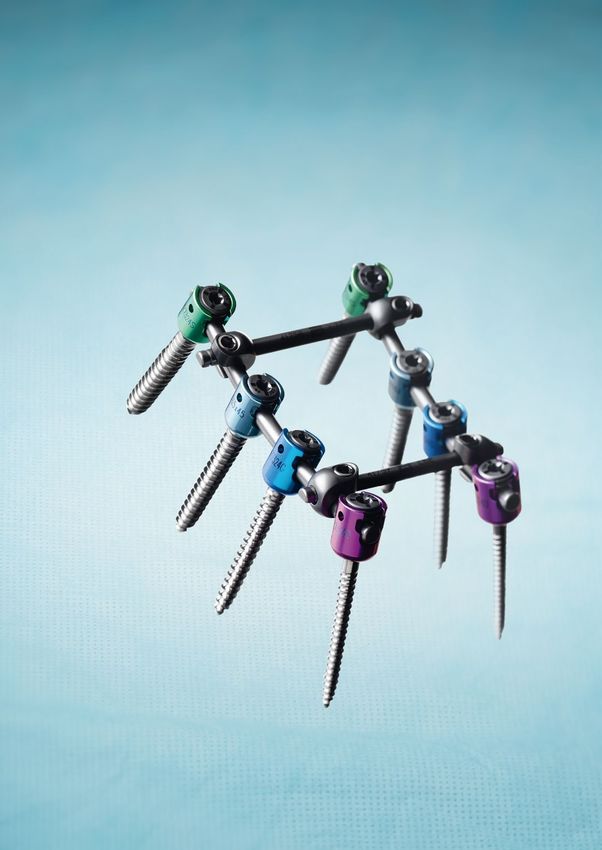
Instinct™ Java® System
Your everyday spinal fixation solution

Surgical Technique

Solutions by the people of Zimmer Spine.
zimmerspine.eu
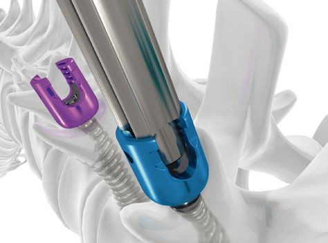
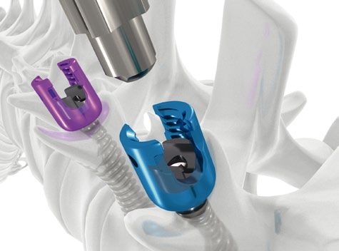
Table of Contents
        Indications/Contraindications   5

        Instrumentation                 6

        Bone Preparation                10

        Verification                     11

        Tapping                         11

        Inserting the screw             12

        Placing the rod                 13

        Rod reduction                   14

        Construct stabilization         17

        Reduction maneuvers             18

        Final tightening                19

        Implant removal                 20

        References                      21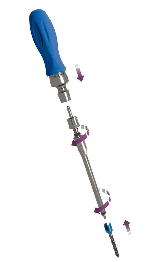
The InstinctTM Java® System was designed to treat a large variety of spinal diseases with intuitive solutions. We
    focused our design activities to deliver a simple, easy-to-use system that offers versatile options to the surgeons.
    Zimmer Spine committed to develop a system that offered low profile implants with high biomechanical strength.
    The Instinct Java System is based on optimized technologies that minimize the overall implants volume without
    compromising the performance.

                       Comprehensive                                                       Proven
                       Surgical technique                                                 Technology

                                                       Instinct
                                                       System

                           Versatile                                                       Simple
                            Solutions                                                       To use

    • Reduced head diameter offers more room for graft with a lower construct profile.

    • Round shape preserves adjacent facets.

    • Four recesses for a powerful connection with the persuader.

    • Raised dimples for a better connection to the rod fork.

    • Optimized buttress thread prevents head splay and cross threading.

    • Star connection provides a stable and strong connection with the screwdriver.

    • Cortical and cancellous advanced threads to maximize the pull-out resistance.

    • Self tapping tip to save surgical time.

4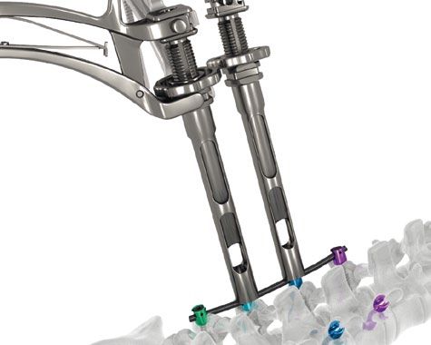
Indications/Contraindications

Indications
Instinct™ Spinal Fixation Systems are designed for posterior spinal fixation procedures.

Instinct™ Spinal Fixation Systems are indicated for the temporary correction and stabilization of a portion of
the vertebral column from the thoracic vertebras to the sacrum until fusion takes place usually in a 6 to 12
months period.

When fusion is achieved the Instinct™ Spinal Fixation Systems should be removed taking into account the
risk/benefit for the patient.

Instinct™ Spinal Fixation Systems are indicated to achieve fusion in the thoracic and lumbar spine for
documented degenerative diseases of the thoracic and lumbar spine, disk herniation, spondylolisthesis,
fractures, spinal stenosis, spinal deformities such as scoliosis, kyphosis, lordosis, tumor, pseudarthrosis or
revision of failed fusion attempts.

The surgeon should take into account the normal capacity of the Instinct™ Spinal Fixation Systems depending
on his surgical strategy for a given patient in accordance with the state of the art.

Contraindications
Contraindications may be absolute or relative. Circumstances below may reduce the chances of a successful
outcome:
• Any abnormality that affects the normal process of bone remodelling including, but not limited to, severe
  osteoporosis involving the spine, excessive bone absorption, osteopenia, primary or metastatic tumors
  involving the spine, active infection at the site or certain metabolic disorders affecting osteogenesis.
• Insufficient quantity or quality of bone that might inhibit rigid device fixation.
• Previous history of infection.
• Excessive local inflammation.
• Open wounds.
• Any neuromuscular deficit that places an unusually heavy load on the device during the healing period.
• Obesity contributes to spinal loading, which may be excessive enough for failure of the fixation of the
  device or to failure of the device itself.
• Patients having inadequate tissue coverage of the operative site.
• Pregnancy.
• A condition of senility, mental illness or substance abuse. These conditions, among others, may cause the
  patient to ignore certain necessary limitations and precautions in the use of the implant, leading to failure
  or other complications.
• Foreign body sensitivity. When material sensitivity is suspected, appropriate tests should be made prior to
 material selection or implantation.
• Other medical or surgical conditions that would preclude the potential benefits of spinal implant surgery,
 such as the presence of tumor, congenital abnormalities, elevation of white blood cell count (WBC), or
 marked left shift in the WBC differential count.

These contraindications can be relative or absolute and must be taken into account by the physician when
making his decision. The above list is not exhaustive.

                                                                                                                  5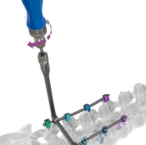
Implants

    Polyaxial Screw   Monoaxial Screw        Blocker
    046W0AN2XXXX      046W0AN3XXXX           046W0AN00002

    Rod               Transverse Connector
    046W0ANXXXXX      SN2023-0-XXXXX

6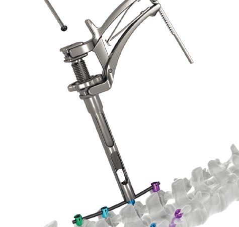
Instrumentation

Square Awl                     Pedicule Probe                   Pedicular Sounder Straight Flexible
046W1AN00500                   046W1AN00530                     046W1AN00520

Tap Ø4.5mm      046W1AN00745
Tap Ø5.5mm      046W1AN00755
Tap Ø6.5mm      046W1AN00765   Polyaxial 3.5 Screwdriver        Monoaxial Screwdriver
Tap Ø7.5mm      046W1AN00775   046W1AN00550                     046W1AN00560

Straight Ratchet Handle        Trial Rod 100mm SN2023-1-00505
046W1AN00570                   Trial Rod 200mm SN2023-1-00506

                                                                                                      7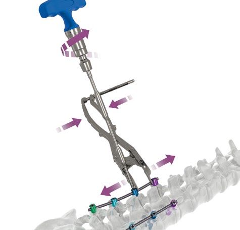
Instrumentation

    Rod Bender             Rod Holder                Rod Pusher
    SN2023-1-00540         046W1AN00620              046W1AN00541

    Rod Fork               Left Rod Bender           Right Rod Bender
    046W1AN00542           SN2023-1-00551            SN2023-1-00554

    Countertorque Wrench   Final Screwdriver Shaft
    046W1AN00660           046W1AN00640

8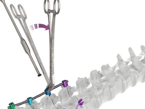
Torque Limiting T-Handle     Blocker Holder               Derotation Forceps
046W1AN00650                 046W1AN00590                 SN2023-1-00610

Alligator Persuader Handle   Alligator Persuader Sleeve   Derotation Forceps
046W1AN00930                 046W1AN00931                 046W1AN00820
                                                          (option)

Contraction Forceps          Distraction Forceps
046W1AN00810                 046W1AN00800

                                                                               9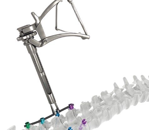
Surgical technique

     Bone Preparation

                          Precise positioning of the pedicle entry point is
                          essential. Proper orientation of the pedicle screw is
                          dependent upon the position of the pilot hole.

                          The pilot hole should be made where a line through
                          the middle of the transverse process crosses a vertical
                          line at the lateral edge of the facet joints (fig.1).

                          A square awl is provided to pierce the bone cortex at
                          the entry point (fig.2).

                          The pedicle probe is inserted through the pilot hole
     Fig. 1
                          into the pedicle to create a path to guide the screw
                          through the pedicle into the vertebral body (fig.3).
                          A depth gauge on the probe indicates the path length.
                          The sagittal orientation of the screw and its degree of
                          convergence is determined by the surgeon, depending
                          on the patient’s anatomy.

     Fig. 2

     Fig. 3

10
Verification
After removing the pedicle probe, the pedicle sounder
straight flexible is inserted to verify the integrity of the
pedicle and the vertebral body walls.
When fully inserted, a forceps can be clamped onto the
pedicle sounder straight flexible to determine the path
depth for choosing the screw size (fig.4).
Fig. 4
Tapping
The appropriate diameter tap is connected to the
straight ratchet handle, inserted and rotated clockwise
(fig.5).
After removing the tap by turning it counterclockwise,
the surgeon should verify the anatomical integrity with
the pedicle sounder straight flexible.
Fig. 5
11Surgical technique
Inserting the screw
The polyaxial or monoaxial screwdriver is connected to
the straight ratchet handle (fig.6).
The appropriate polyaxial screw is placed on the
polyaxial 3.5 screwdriver by aligning the screwdriver
tip to the female hex on the screw shank. The polyaxial
screw is fixed by screwing the polyaxial 3.5 screwdriver
sleeve clockwise into the screw head.
The appropriate monoaxial screw is placed on the
monoaxial screwdriver and fixed by screwing the
sleeve clockwise into the screw head.
The polyaxial or monoaxial screwdriver sleeve is locked
Fig. 7
by turning the collet clockwise. This secure locking
system prevents screw loosening during insertion. Do
not overtighten the collet.
The screw is inserted through the pedicle pathway
1 until it reaches the proper dorsal height (fig.7).
The polyaxial or monoaxial screwdriver is released by
unlocking the collet counterclockwise. The sleeve can
then be turned counterclockwise to loosen the screw
2
head (fig.8).
This procedure is repeated for all the screws of the
construct.
For cleaning, the screwdriver is disassembled. The
Fig. 8
handle is disconnected from the shaft, then the collet
and the sleeve are removed from the top (fig.9).
Warning: Choose screw size and diameter according to the patient’s
anatomy and surgeon preference. It is recommended to use diameters
4.5mm and 5.5mm on the thoracic spine.
Fig. 6 Fig. 9
12Placing the rod
Use the rod bender to prepare and contour the rods
by progressive bends (fig.10) until obtaining a shape
similar to that defined by the trial rod.
In the case of short rods (30 to 100 mm), pre-contoured
versions simplify the initial approximation.
Fig. 10
The proximal tip of the blocker holder can be used to
adjust the head alignments.
The rod is positioned within the heads using the rod
holder (fig.11).
Once the rod has been placed in the screw heads, the
blockers are picked up with the blocker holder with the
etched cross oriented upward.
The blocker holder is aligned in the direction of the
screw head and the blocker is introduced (fig.12).
The blocker is turned until coming into contact with the
Fig. 11 rod, but not tightened. The same procedure is used for
all the blockers of the construct.
Fig. 12
13Surgical technique
Rod reduction
For any rod approximation, the Instinct System offers
three options for rod reduction.
For the smallest reductions, the rod pusher can be
used to directly introduce the rod into the screw head
(fig.13).
Fig. 13
For moderate reductions, the rod fork may be used.
When using the rod fork, the prongs of the forceps
should be aligned vertically in the screw head dimples.
Lock the rod fork ratchet mechanism and use the rod
as a lever to introduce the rod into the screw head
(fig.14). Insert the blocker with the blocker holder
(fig 15).
Fig. 14
Fig. 15
14For substantial reductions, the Alligator persuader is
used to seat the rod in place. The four prongs at the
distal part of the shaft are aligned with the screw head
recesses (fig.16).
Fig. 16
By squeezing the handle, the prongs come into contact
with the screw head to provide stable fixation, the
external sleeve slides onto the shaft to push the rod
into the screw head (fig.17).
The ratchet offers a controlled reduction maneuver.
The knob may be screwed clockwise until it reaches
the sleeve in order to maintain the reduction (fig.18).
Fig. 17 Fig. 18
The handle may then be removed by pressing the
lateral button and used subsequently with another
persuader shaft (fig.19).
Fig. 19
15Surgical technique
The handle can be used in the sagittal plane or in the
frontal plane (fig.20), depending on the surgeon’s
preference.
Fig. 20
When the desired reduction is achieved, the blocker
is advanced through the persuader shaft using the
blocker holder (fig.21).
The persuader is removed by unscrewing the knob
and releasing the handle ratchet (fig.22). Pull the
sleeve on the maximal position to totally disconnect
the screw head.
The Alligator persuader can be disassembled for
cleaning (fig. 23). The handle is removed by pushing
on the locking button and then pulling down the sleeve
to remove it from the shaft. The knob is unscrewed in
the clockwise position to be removed from the shaft.
Fig. 21
Fig. 22 Fig. 23
16Construct stabilization
To increase the stability of the construct a transverse
connector may be used to connect the two rods.
The transverse connectors are preassembled to be
used in distraction (fig.24). However, the hooks can
be removed from the rod on the etched arrow side and
can be set in reverse position to be used in contraction
(fig.25).
Fig. 24
Fig. 25
Once the transverse connector is placed on the
longitudinal rods, the two connector blocks are
distracted (or contracted) until they snap onto the
rods.
The blockers are then locked with the polyaxial 3.5mm
screwdriver in the desired position (fig.26).
Fig. 26
17Surgical technique
Reduction maneuvers
Reduction maneuvers can be achieved by using the
contraction forceps, distraction forceps, derotation
forceps or in situ benders.
Contraction is achieved by locking one implant then
placing the contraction forceps cephalad and caudal
to the screw heads. Then the handle is squeezed until
contraction is completed.
Distraction is achieved by locking one implant then
placing the distraction forceps between the screw
heads and squeeze the handle until the distraction is
achieved (fig.27).
Fig. 27
Once reduction maneuvers are complete, a primary
tightening of the implants is mandatory to avoid
loosening of the reduction when the forceps are
removed.
In situ bending can be achieved by using the right and
left rod benders (fig.28). The implants are temporarily
locked, and the benders are used in the sagittal plane
to restore the lordotic curve.
Derotation maneuvers may be performed with the
derotation forceps (fig.29). The strength of the forceps
is adjustable by turning the collet located at the
proximal part of the handle.
Fig. 28 Fig. 29
18Final tightening
Once all the reduction maneuvers have been
completed, all the blockers must be locked.
The final screwdriver shaft must be assembled to the
Torque limiting T-handle.
The final screwdriver is inserted in the counter-
torque wrench and connected to the blocker (fig.30)
to perform the final tightening without transferring
torsion to the construct or to the spine.
Turn the screwdriver clockwise until the Torque limiting
T-handle releases (fig.31).
Warning: Always use the torque limiting T-handle
for the final tightening.
Fig. 30
Fig. 31
19Surgical technique
Implant removal
For revision surgeries, the blockers are removed by
placing the counter-torque wrench on the screw head
and inserting the final screwdriver shaft into each
blocker, which is turned counterclockwise (fig.32).
Remove the rod and use the blocker holder tip to
mobilize the polyaxial screw head.
The procedure is repeated for all the screws of the
construct.
Engage the polyaxial 3.5 screwdriver tip into the female
star on the screw shank. Screw the sleeve into the
screw head (see page 3) and turn counterclockwise to
remove the screw from the vertebra (fig.33).
Fig. 32 Fig. 33
Note: If the ring is not set in the rod axis, use the proximal tip of the
blocker holder to align the ring in the proper direction (fig.34a&b).
Fig. 34a
Fig. 34b
20References
Instruments
Nomenclature Catalog number Nomenclature Catalog number
Square awl 046W1AN00500 Tap Ø7.5 mm 046W1AN00775
Pedicular sounder straight flexible 046W1AN00520 Distraction forceps 046W1AN00800
Pedicule Probe 046W1AN00530 Contraction forceps 046W1AN00810
Rod pusher 046W1AN00541 Derotation forceps SN2023-1-00610
Rod fork 046W1AN00542 Alligator Persuader handle 046W1AN00930
Polyaxial 3.5 Screwdriver 046W1AN00550 Alligator Persuader sleeve 046W1AN00931
Monoaxial Screwdriver 046W1AN00560 Trial rod 100 mm SN2023-1-00505
Straight ratchet handle 046W1AN00570 Trial rod 200 mm SN2023-1-00506
Blocker holder 046W1AN00590 Rod bender SN2023-1-00540
Rod holder 046W1AN00620 Left rod bender SN2023-1-00551
Final Screwdriver Shaft 046W1AN00640 Right rod bender SN2023-1-00554
Torque limiting T-Handle 046W1AN00650 Sterilization Case Lid 07.01260.001
Countertorque wrench 046W1AN00660 Instrument container base 046W2AN00032
Tap Ø4.5 mm 046W1AN00745 Instrument container upper tray 046W2AN00033
Tap Ø5.5 mm 046W1AN00755 Instrument container lower tray 046W2AN00034
Tap Ø6.5mm 046W1AN00765
Option
Nomenclature Catalog number
Derotation forceps 046W1AN00820
21Implants
Nomenclature Catalog number Nomenclature Catalog number
Polyaxial Pedicle Screw Ø4,5 lg 35 046W0AN24535 Monoaxial Pedicle Screw Ø4.5 L35 046W0AN34535
Polyaxial Pedicle Screw Ø4,5 lg 40 046W0AN24540 Monoaxial Pedicle Screw Ø4.5 L40 046W0AN34540
Polyaxial Pedicle Screw Ø4,5 lg 45 046W0AN24545 Monoaxial Pedicle Screw Ø4.5 L45 046W0AN34545
Polyaxial Pedicle Screw Ø5,5 lg 35 046W0AN25535 Monoaxial Pedicle Screw Ø5.5 L35 046W0AN35535
Polyaxial Pedicle Screw Ø5,5 lg 40 046W0AN25540 Monoaxial Pedicle Screw Ø5.5 L40 046W0AN35540
Polyaxial Pedicle Screw Ø5,5 lg 45 046W0AN25545 Monoaxial Pedicle Screw Ø5.5 L45 046W0AN35545
Polyaxial Pedicle Screw Ø5,5 lg 50 046W0AN25550 Monoaxial Pedicle Screw Ø5.5 L50 046W0AN35550
Polyaxial Pedicle Screw Ø6,5 lg 35 046W0AN26535 Monoaxial Pedicle Screw Ø6.5 L35 046W0AN36535
Polyaxial Pedicle Screw Ø6,5 lg 40 046W0AN26540 Monoaxial Pedicle Screw Ø6.5 L40 046W0AN36540
Polyaxial Pedicle Screw Ø6,5 lg 45 046W0AN26545 Monoaxial Pedicle Screw Ø6.5 L45 046W0AN36545
Polyaxial Pedicle Screw Ø6,5 lg 50 046W0AN26550 Monoaxial Pedicle Screw Ø6.5 L50 046W0AN36550
Polyaxial Pedicle Screw Ø6,5 lg 55 046W0AN26555 Monoaxial Pedicle Screw Ø6.5 L55 046W0AN36555
Polyaxial Pedicle Screw Ø6,5 lg 60 046W0AN26560 Monoaxial Pedicle Screw Ø6.5 L60 046W0AN36560
Polyaxial Pedicle Screw Ø7,5 lg 35 046W0AN27535 Monoaxial Pedicle Screw Ø7.5 L35 046W0AN37535
Polyaxial Pedicle Screw Ø7,5 lg 40 046W0AN27540 Monoaxial Pedicle Screw Ø7.5 L40 046W0AN37540
Polyaxial Pedicle Screw Ø7,5 lg 45 046W0AN27545 Monoaxial Pedicle Screw Ø7.5 L45 046W0AN37545
Polyaxial Pedicle Screw Ø7,5 lg 50 046W0AN27550 Monoaxial Pedicle Screw Ø7.5 L50 046W0AN37550
Polyaxial Pedicle Screw Ø7,5 lg 55 046W0AN27555 Monoaxial Pedicle Screw Ø7.5 L55 046W0AN37555
Polyaxial Pedicle Screw Ø7,5 lg 60 046W0AN27560 Monoaxial Pedicle Screw Ø7.5 L60 046W0AN37560
Monoaxial Pedicle Screw Ø8.5 L35 046W0AN38535
Monoaxial Pedicle Screw Ø8.5 L40 046W0AN38540
Monoaxial Pedicle Screw Ø8.5 L45 046W0AN38545
Monoaxial Pedicle Screw Ø8.5 L50 046W0AN38550
Monoaxial Pedicle Screw Ø8.5 L55 046W0AN38555
Monoaxial Pedicle Screw Ø8.5 L60 046W0AN38560
22Optional Straight Rods
Nomenclature Catalog number Nomenclature Catalog number
Pre-Contoured Rod Ø5,5 L30 046W0AN51030 Straight Rod Ø5,5 L30 046W0AN50030
Pre-Contoured Rod Ø5,5 L40 046W0AN51040 Straight Rod Ø5,5 L40 046W0AN50040
Pre-Contoured Rod Ø5,5 L50 046W0AN51050 Straight Rod Ø5,5 L50 046W0AN50050
Pre-Contoured Rod Ø5,5 L60 046W0AN51060 Straight Rod Ø5,5 L60 046W0AN50060
Pre-Contoured Rod Ø5,5 L70 046W0AN51070 Straight Rod Ø5,5 L70 046W0AN50070
Pre-Contoured Rod Ø5,5 L80 046W0AN51080 Straight Rod Ø5,5 L80 046W0AN50080
Pre-Contoured Rod Ø5,5 L90 046W0AN51090 Straight Rod Ø5,5 L90 046W0AN50090
Pre-Contoured Rod Ø5,5 L100 046W0AN51100 Straight Rod Ø5,5 L100 046W0AN50100
Straight rod Ø5,5 120 046W0AN50120 Straight Rod Ø5,5 L400 046W0AN50400
Straight rod Ø5,5 160 046W0AN50160
Straight rod Ø5,5 200 046W0AN50200
Transverse Connector Ø5,5 L52 SN2023-0-52055
Transverse Connector Ø5,5 L62 SN2023-0-62055
Transverse Connector Ø5,5 L72 SN2023-0-72055
Transverse Connector Ø5,5 L82 SN2023-0-82055
Blocker 046W0AN00002
Sterilization Case Lid 07.01260.001
Implant container base 046W2AN00012
Implant container polyaxial caddy 046W2AN00013
Implant container monoaxial caddy 046W2AN00014
Implant container blocker caddy 046W2AN00015
Implant container rod tray 046W2AN00016
23Solutions by the people of Zimmer Spine.
You are devoted to helping your patients reduce their pain and improve their lives.
And the people of Zimmer Spine are devoted to you. We are dedicated to supporting
you with best-in-class tools, instruments and implants. We are driven by the opportunity
to share our unrivaled education and training. We are committed partners who will
do everything in our power to assist you in your quest to provide the absolute best in
spinal care. And we can be counted on always to act with integrity as ethical partners
who are worthy of your trust. We are the people of Zimmer Spine.
Disclaimer
This documentation is intended exclusively for physicians and is not intended
for laypersons.
Information on the products and procedures contained in this document is of a
general nature and does not represent and does not constitute medical advice
or recommendations. Because this information does not purport to constitute any
diagnostic or therapeutic statement with regard to any individual medical case, each
patient must be examined and advised individually, and this document does not
replace the need for such examination and/or advice in whole or in part.
Please refer to the package inserts for important product information, including,
but not limited to, contraindications, warnings, precautions, and adverse effects.
Responsible manufacturer
Zimmer Spine
Cité Mondiale
23, parvis des Chartrons
33080 Bordeaux - France
Tel +33(0)5 56 00 18 20
Fax 33 (0)5 56 00 18 21
www.zimmerspine.eu
© 2010 Zimmer Spine
Lit. N° 06.01811.012 - Ed 2010-09
046E5AN00TEN - Sep 2010 - V2 0459
+H84406018110121/$100901I10WYou can also read