Juno System User Guide - Fluidigm
←
→
Page content transcription
If your browser does not render page correctly, please read the page content below
100-7070 Rev 13

Juno System
User Guide

For Research Use Only. Not for use in diagnostic procedures.

Information in this publication is subject to change without notice. It is
Fluidigm policy to improve products as new techniques and
components become available. Therefore, Fluidigm reserves the right
to change specifications at any time. Every effort has been made to
avoid errors in the text, diagrams, illustrations, figures, and screen
captures. However, Fluidigm assumes no responsibility for any errors or
omissions. In no event shall Fluidigm be liable for any damages in
connection with or arising from the use of this publication.

Patent and Limited License Information
Fluidigm products are covered by issued and pending patents in the
United States and other countries. Patent and limited license
information is available at fluidigm.com/legal/notices.

Limited Use License to Perform Preamplification with Fluidigm IFCs
A license to use Thermo Fisher Scientific’s patented preamplification
method workflows involving a Fluidigm integrated fluidic circuit (IFC)
can be obtained (i) with purchase of a Fluidigm IFC from Fluidigm
Corporation or (ii) by a separate license from Thermo Fisher Scientific.
For licensing information, contact outlicensing@lifetech.com.

Limited Digital PCR License
A license to use Thermo Fisher Scientific’s patented digital PCR method
in all fields other than in the Sequencing Field, the Mass Spectrometry
Field, and the Prenatal Field in workflows involving a Fluidigm IFC can
be obtained (i) with purchase of a Fluidigm IFC from Fluidigm
Corporation or (ii) by a separate license from Thermo Fisher Scientific.
For licensing information, contact outlicensing@lifetech.com.

Trademarks
Fluidigm, the Fluidigm logo, 48.Atlas, Advanta, Biomark, D3, Digital
Array, Dynamic Array, EP1, Flex Six, Juno, qdPCR 37K, and SNP Type
are trademarks and/or registered trademarks of Fluidigm Corporation in
the United States and/or other countries. All other trademarks are the
sole property of their respective owners.

© 2021 Fluidigm Corporation. All rights reserved. 03/2021

For technical support visit techsupport.fluidigm.com.
North America +1 650 266 6100 | Toll-free (US/CAN): 866 358 4354 | techsupport@fluidigm.com
Latin America +1 650 266 6100 | techsupportlatam@fluidigm.com
Europe/Middle East/Africa/Russia +33 1 60 92 42 40 | eu.support@fluidigm.com
Japan +81 3 3662 2150 | techsupportjapan@fluidigm.com
China (excluding Hong Kong) +86 21 3255 8368 | techsupportchina@fluidigm.com
All other Asian countries/India/Australia +1 650 266 6100 | techsupportasia@fluidigm.com

2                                                                                             Juno System User Guide

Contents
About This Guide                              5    Shut Down the System and Then the
                                                   Instrument                                 35
Purpose                                        5

Safety Alert Conventions                       5
                                                   Chapter 3: Using Advanced Features
Safety Alerts for Chemicals                    5
                                                   of Juno                                    37
Safety Alerts for Instruments                  5   Log In                                     37
Safety Data Sheets                             6   Log Out                                    37

Chapter 1: Introducing the Juno                    Manage Scripts                             38
System                                        7    Enable Advanced Scripts                    38
                                                   Export Scripts to a USB                    38
The Juno System                                7   Install Scripts from a USB                 39
Consumables Ordering                           8   Modify Scripts                             40
Components of the Juno System                  8   To View the Scripts to Modify              40
                                                   To Change General Properties of a Script   41
Interface Plates and IFCs                     11   To Change Thermal Properties of a Script   41
System Software                               11   To Remove a Script                         43

Scripts                                       12   Manage Users                               43
Basic Scripts                                 12   Change the Date and Time                   45
Advanced Scripts                              15
                                                   Update the System                          46
Components Included in Shipping Box           16
                                                   Enable In-House Air                        47
Optional Components                           16

System Functions                              17   Appendix A: Troubleshooting                48

Air Options                                   17   Powering ON/OFF                            48

Regulatory Compliance                         17   Loading                                    49
General Regulations and Requirements          17   Running                                    50
Harmonized Standards                          17
Conformity Symbols on the Instrument          18   Cleaning                                   50

Chapter 2: Getting Started with Juno          19   Appendix B: Preventive Maintenance,
                                                   Decontamination, and Disposal              51
Start the Juno System                         19
                                                   Preventive Maintenance                     51
How to Use the Juno Touchscreen               21   Preventive Maintenance Recommendations     51
Start a Run                                   21   Clean the Thermal Cycler Chuck             51
Load an IFC                                   21   Clean an Interface Plate                   52
Select a Script                               24   Clean the Juno System                      54
Schedule the Harvest with the LP 192.24, LP        Clean the Touchscreen                      56
48.48, LP 8.8.6, or 48.Atlas IFC              25   Replace the Fuses                          56
Run a Script                                  25
                                                   Decontamination                            57
Switch an Interface Plate                     27
                                                   Biological Agents                          57
Install an Interface Plate                    30
                                                   Hazardous Chemicals                        57
View System Information                       33   Radioactive Materials                      57

Export a Log                                  34   Disposal of Products                       58

Juno System User Guide                                                                         3
Contents

Appendix C: Related Documents   59

Appendix D: Safety              60
General Safety                  60

Instrument Safety               60

Symbols on the Instrument       61

Electrical Safety               61

Chemical Safety                 62

4                                    Juno System User Guide
About This Guide
IMPORTANT Before using the instrument, read and understand the safety guidelines in this
document. Failure to follow these guidelines may result in undesirable effects, injury to
personnel, and/or damage to the instrument or to property.

Purpose
This guide describes how to use the Juno™ system, including the instrument and the system
software. For complete instrument specifications and unpacking/installation instructions, see
the Juno System Site Requirements Guide (PN 100-7072).

Safety Alert Conventions
            CAUTION ABBREVIATED SAFETY ALERTS. Hazard symbols and hazard types
            specified in procedures may be abbreviated in this document. For complete safety
            information, see Appendix D.
Fluidigm documentation uses specific conventions for presenting information that may
require your attention. Refer to the following safety alert conventions.

Safety Alerts for Chemicals
For hazards associated with chemicals, this document follows the United Nations Globally
Harmonized System of Classification and Labelling of Chemicals (GHS) and uses indicators
that include a pictogram and a signal word that indicates the severity level:

Indicator      Description
               Pictogram (see example) consisting of a symbol on a white background within a red
               diamond-shaped frame. Refer to the individual safety data sheet (SDS) for the applicable
               pictograms and hazards pertaining to the chemicals being used.

DANGER         Signal word that indicates more severe hazards.
WARNING        Signal word that indicates less severe hazards.

Safety Alerts for Instruments
For hazards associated with instruments, this document uses indicators that include a
pictogram and signal words that indicate the severity level:

Indicator        Description
                 Pictogram (see example) consisting of a symbol on a white background within a black
                 triangle-shaped frame. Refer to the instrument user guide for the applicable pictograms
                 and hazards pertaining to instrument usage.
DANGER           Signal word that indicates an imminent hazard that will result in severe injury or death
                 if not avoided.
WARNING          Signal word that indicates a potentially hazardous situation that could result in serious
                 injury or death if not avoided.

Juno System User Guide                                                                                       5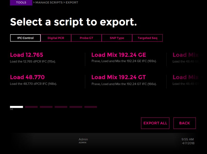
About This Guide
Safety Data Sheets

Indicator      Description
CAUTION        Signal word that indicates a potentially hazardous situation that could result in minor or
               moderate personal injury if not avoided.
IMPORTANT      Signal word that indicates information necessary for proper use of products or
               successful outcome of experiments.

Safety Data Sheets
Read and understand the SDSs before handling chemicals. To obtain SDSs for chemicals
ordered from Fluidigm, either alone or as part of this system, go to fluidigm.com/sds and
search for the SDS using either the product name or the part number.

Some chemicals referred to in this user guide may not have been provided with your system.
Obtain the SDSs for chemicals provided by other manufacturers from those manufacturers.

6                                                                                                   Juno System User Guide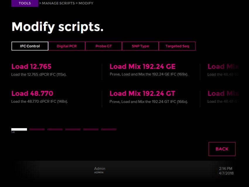
Chapter 1: Introducing the Juno System
The Juno System
The Juno™ system is used for preparing libraries for next-generation sequencing (NGS) and
IFC preparation for gene expression, genotyping and digital PCR applications.

NOTE For Research Use Only. Not for use in diagnostic procedures.

Library Preparation IFCs

The Juno system enables NGS library preparation for Illumina® sequencers. Juno performs
sample and assay loading, mixing, thermal cycling, and harvesting automatically for further
processing and sequencing.

•   The LP 192.24 IFC facilitates parallel amplification and barcode indexing of up to 192
    samples with up to 2,400 assays for targeted sequencing.

•   The LP 48.48 IFC facilitates parallel amplification and barcode indexing of up to
    48 samples with up to 4,800 assays for targeted sequencing.

•   The LP 8.8.6 IFC contains 6 discrete partitions. Each partition processes up to 8 samples
    against 8 assay pools, which allows you to simultaneously process up to 6 sample sets
    with different assay panels. A user may fill an IFC with 1 panel or process multiple panels
    on a single IFC. Choose from a growing menu of Advanta™ NGS Library Prep Assays that
    includes panels for Solid Tumor* and RNA Fusions† or create custom panels through the
    D3™ assay design portal at fluidigm.com/d3.

•   The 48.Atlas™ IFC enables the preparation of NGS-ready, dual-indexed, full-length cDNA
    libraries of poly(A) RNA utilizing total RNA isolated from human, mouse, or rat for
    subsequent sequencing analysis. The complete workflow is automated for 48 samples
    per IFC.

Genotyping, Digital PCR, and Gene Expression IFCs

Juno also processes all Fluidigm IFC formats that support genotyping, digital PCR and gene
expression applications.

•   The Juno 96.96 Genotyping IFC integrates preamplification and genotyping reactions of
    up to 96 samples and 96 genotyping assays in a single workflow.

•   For genotyping experiments using Dynamic Array™ and Flex Six™ IFCs, Juno performs IFC
    priming, sample and assay loading, and thermal-cycling. For digital PCR experiments
    using Digital Array™ IFCs, Juno performs priming, sample and assay loading, and
    thermal-cycling. After being prepared on the Juno system, the IFC is scanned on the
    Biomark™ HD system or EP1™ system to collect data for later analysis.

* Requires the Advanta Solid Tumor NGS Library Prep Assay (Fluidigm PN 101-7033).
† Requires the Advanta RNA Fusions NGS Library Prep Assay (Fluidigm PN 101-8654).

Juno System User Guide                                                                            7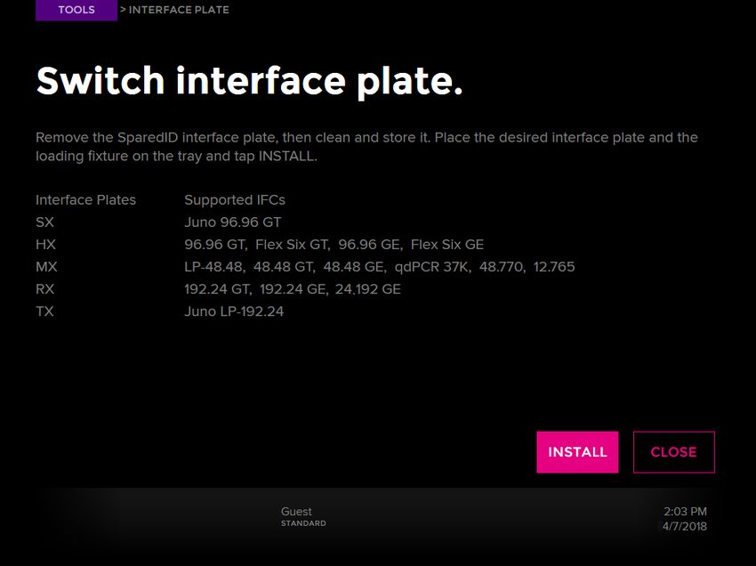
Chapter 1: Introducing the Juno System
Consumables Ordering

•   For gene expression experiments using Dynamic Array, and Flex Six IFCs, Juno performs
    IFC priming as well as sample and assay loading. After being prepared on the Juno
    system, the IFC is thermal-cycled and scanned on the Biomark HD system to collect data
    for later analysis.

Consumables Ordering
To reorder IFCs and reagents, contact your regional Fluidigm sales representative or
distributor. Go to fluidigm.com/contact.html.

Components of the Juno System

                                                       Touchscreen
                                                       interface

                                                       Retracted tray

                                                       Power and
                                                       standby indicator

Figure 1. Front panel of the Juno instrument.

8                                                                                      Juno System User Guide
Chapter 1: Introducing the Juno System
                                                                                      Components of the Juno System

Compressed
air input

DVI port

USB 2.0 ports
Ethernet
port                                                                              Exhaust fan

ON/OFF switch

Power socket

Figure 2. Back panel of the Juno instrument. There are also 2 USB 2.0 ports on the side of the
instrument.

                                                                   White notch

Figure 3. Tray and thermal chuck of the Juno instrument. The white notch is used to orient the notched
corner of the IFC in the tray.

Juno System User Guide                                                                                               9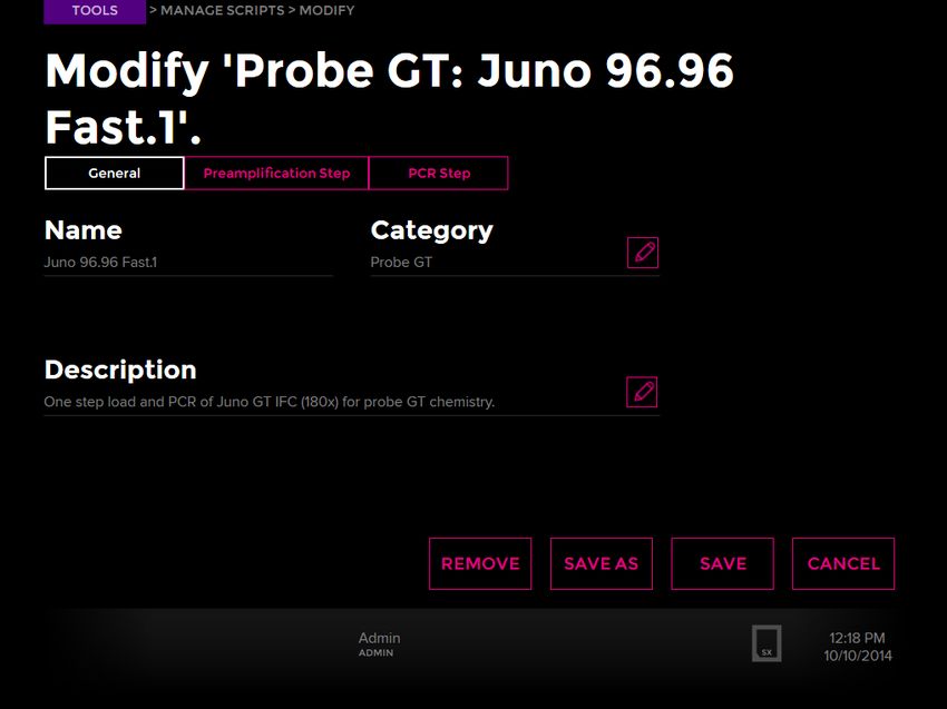
Chapter 1: Introducing the Juno System
Components of the Juno System

Figure 4. Interface Plate Loading Fixture

Figure 5. MX Interface Plate

10                                          Juno System User Guide
Chapter 1: Introducing the Juno System
                                                                                             Interface Plates and IFCs

Interface Plates and IFCs
Table 1 shows the appropriate interface plate for the IFC you are using.

Table 1. Interface plates and supported IFCs

Interface Plate Name     Label Color on Interface Plate   Supports…

MX                       Black                            48.48 Dynamic Array™ IFCs
                                                          LP 48.48 IFC
                                                          LP 8.8.6
                                                          qdPCR 37K™ IFC
                                                          48.770 Digital Array™ IFC
                                                          12.765 Digital Array IFC

SX                       Silver                           Juno 96.96 Genotyping IFC

HX                       Green                            96.96 Dynamic Array IFCs
                                                          Flex Six™ Genotyping and Gene Expression IFCs

RX                       Red                              192.24 Genotyping and Gene Expression IFCs
                                                          24.192 Dynamic Array IFC for Gene Expression

TX                       Blue                             LP 192.24 IFC
                                                          48.Atlas™ IFC

System Software
Ensure that you have installed the Juno system software v3.1 or later if you are using the Juno
96.96 Genotyping IFC. Install software v3.5 or later if you are using the Juno 96.96
Genotyping IFC or an IFC for the Targeted DNA Sequencing Library application. Install
software v3.11.1 or later if you are using the 24.192 Dynamic Array IFC for Gene Expression.
Install software v3.14.1 or later if you are using the 48.Atlas IFC. To get the latest system
software, go to fluidigm.com/software.

Juno System User Guide                                                                                              11
Chapter 1: Introducing the Juno System
Scripts
Scripts
Basic Scripts
Tab in Juno Scripts for IFCs Controller/Interface Script Descriptions
Software Plate to Use*
(label color)
Targeted Seq 48.Atlas RNA-Seq LP TX (blue) One step load mix, PCR, and harvest of
48.Atlas IFC (197x)
One Step LP-192.24 TX (blue) One step load mix, PCR, and harvest of
LP 192.24 IFC (192x)
One Step LP-48.48 MX (black) One step load mix, PCR, and harvest of
LP 48.48 IFC (155x)
One Step LP-8.8.6 MX (black) One step load mix, PCR, and harvest of
LP 8.8.6 IFC (156x)
Prime LP-48.48 MX (black) Preparation of the LP 48.48 IFC (155x) for
loading
Digital PCR One Step 12.765 MX (black) One step load and PCR of the 12.765 dPCR IFC
(115x)
One Step 48.770 MX (black) One step load and PCR of the 48.770 dPCR IFC
(148x)
One Step qdPCR 37K MX (black) One step load and PCR of the qdPCR 37K IFC
(167x)
12 Juno System User GuideChapter 1: Introducing the Juno System
Scripts
Tab in Juno Scripts for IFCs Controller/Interface Script Descriptions
Software Plate to Use*
(Continued) (label color)
IFC Control Load 12.765 MX (black) Load the 12.765 dPCR IFC (115x)
Load 48.770 MX (black) Load the 48.770 dPCR IFC (148x)
Load Mix 192.24 GE RX (red) Prime, load, and mix the 192.24 GE IFC (169x)
Load Mix 24.192 GE RX (red) Prime, load, and mix the 24.192 GE IFC (158x)
Load Mix 48.48 GE MX (black) Load the 48.48 GE IFC (113x)
Load Mix 96.96 GE HX (green) Load the 96.96 GE IFC (136x)
Load Mix Flex Six GE HX (green) Load the Flex Six GE IFC (153x)
Load qdPCR 37K MX (black) Load qdPCR 37K IFC (167x)
Post Run Flex Six GE HX (green) Preparation of the Flex Six GE IFC (153x) for
storage
Post Run Flex Six GT HX (green) Preparation of the Flex Six GT IFC (154x) for
storage
Prime 12.765 MX (black) Preparation of the 12.765 dPCR IFC (115x) for
loading
Prime 48.48 GE MX (black) Preparation of the 48.48 GE IFC (113x) for
loading
Prime 48.48 GT MX (black) Preparation of the 48.48 GT IFC (124x) for
loading
Prime 48.770 MX (black) Preparation of the 48.770 dPCR IFC (148x) for
loading
Prime 96.96 GE HX (green) Preparation of the 96.96 GE IFC (136x) for
loading
Prime 96.96 GT HX (green) Preparation of the 96.96 GT IFC (138x) for
loading
Prime Flex Six GE HX (green) Preparation of the Flex Six GE IFC (153x) for
loading
Prime Flex Six GT HX (green) Preparation of the Flex Six GT IFC (154x) for
loading
Prime qdPCR 37K MX (black) Preparation of the qdPCR 37K IFC (167x) for
loading
Juno System User Guide 13Chapter 1: Introducing the Juno System
Scripts
Tab in Juno Scripts for IFCs Controller/Interface Script Descriptions
Software Plate to Use*
(Continued) (label color)
Probe GT Juno 96.96 Fast SX (silver) One step load and PCR of Juno GT IFC (180x)
for probe GT chemistry
One Step 192.24 Fast RX (red) One step load and fast PCR of 192.24 GT IFC
(166x) for probe GT chemistry
One Step 48.48 MX (black) One step load and standard PCR of 48.48 GT
IFC (124x) for probe GT chemistry
One Step 48.48 Fast MX (black) One step load and fast PCR of 48.48 GT IFC
(124x) for probe GT chemistry
One Step 96.96 HX (green) One step load and standard PCR of 96.96 GT
IFC (138x) for probe GT chemistry
One Step 96.96 Fast HX (green) One step load and fast PCR of 96.96 GT IFC
(138x) for probe GT chemistry
One Step Flex Six HX (green) One step load and standard PCR of Flex Six GT
IFC (154x) for probe GT chemistry
One Step Flex Six Fast HX (green) One step load and fast PCR of Flex Six GT IFC
(154x) for probe GT chemistry
SNP Type Juno 96.96 SX (silver) One step load and PCR of Juno GT IFC (180x)
for SNP Type™ chemistry
One Step 192.24 RX (red) One step load and PCR of 192.24 GT IFC (166x)
for SNP Type chemistry
One Step 48.48 MX (black) One step load and PCR of 48.48 GT IFC (124x)
for SNP Type chemistry
One Step 96.96 HX (green) One step load and PCR of 96.96 GT IFC (138x)
for SNP Type chemistry
One Step Flex Six HX (green) One step load and PCR of Flex Six GT IFC
(154x) for SNP Type chemistry
* The interface plates are distinguished by color labels and 2-letter names. See the scripts table on page 11.
14 Juno System User GuideChapter 1: Introducing the Juno System
Scripts
Advanced Scripts
NOTE To view advanced scripts on the instrument, log in as an administrator, tap
Preferences, then select Enabled under Advanced Scripts.
Tab in Juno Scripts for IFCs Controller/ Script Descriptions
Software Interface
Plate to
Use*
(label color)
Targeted Seq Load Mix LP-192.24 TX (blue) Load and mix samples and assays for LP 192.24 IFC (192x)
PCR Harvest LP-192.24 TX (blue) PCR and harvest of LP 192.24 IFC (192x)
Load Mix LP-48.48 MX (black) Load and mix samples and assays for LP 48.48 IFC (155x)
Load Mix LP-8.8.6 MX (black) Load and mix samples and assays for LP 8.8.6 IFC (156x)
PCR Harvest LP-48.48 MX (black) PCR and harvest of LP 48.48 IFC (155x)
PCR Harvest LP-8.8.6 MX (black) PCR and harvest of LP 8.8.6 IFC (156x)
Digital PCR PCR 12.765 MX (black) PCR of the 12.765 dPCR IFC (115x)
PCR 48.770 MX (black) PCR of the 48.770 dPCR IFC (148x)
PCR qdPCR 37K MX (black) PCR of the qdPCR 37K IFC (167x)
IFC Control Load Mix 96.96 GT HX (green) Load the 96.96 GT IFC (138x)
Load Mix 48.48 GT MX (black) Load the 48.48 GT IFC (124x)
Load Mix Flex Six GT HX (green) Load the Flex Six GT IFC (154x)
Load Mix 192.24 GT RX (red) Prime, load, and mix the 192.24 GT IFC (166x)
Probe GT Fast PCR 192.24 RX (red) Fast PCR of 192.24 GT IFC (166x) for probe GT chemistry
Fast PCR 48.48 MX (black) Fast PCR of 48.48 GT IFC (124x) for probe GT chemistry
Fast PCR 96.96 HX (green) Fast PCR of 96.96 GT IFC (138x) for probe GT chemistry
Fast PCR Flex Six HX (green) Fast PCR of Flex Six GT IFC (154x) for probe GT chemistry
PCR 96.96 HX (green) Standard PCR of 96.96 GT IFC (138x) for probe GT
chemistry
PCR 48.48 MX (black) Standard PCR of 48.48 GT IFC (124x) for probe GT
chemistry
PCR Flex Six HX (green) Standard PCR of Flex Six GT IFC (154x) for probe GT
chemistry
SNP Type PCR 192.24 RX (red) PCR of the 192.24 GT IFC (166x) for SNP Type chemistry
PCR 48.48 MX (black) PCR of the 48.48 GT IFC (124x) for SNP Type chemistry
PCR 96.96 HX (green) PCR of the 96.96 GT IFC (138x) for SNP Type chemistry
PCR Flex Six HX (green) PCR of the Flex Six GT IFC (154x) for SNP Type chemistry
* The interface plates are distinguished by color labels and 2-letter names. See the scripts table on page 11.
Juno System User Guide 15Chapter 1: Introducing the Juno System
Components Included in Shipping Box
Components Included in Shipping Box
The Juno system (PN 101-6455) includes the following components:
Component Purpose
Juno system Preparation of libraries for NGS sequencing and IFC
preparation for gene expression, genotyping and digital
PCR applications.
Power cable, >10 A, 2 m, IEC C13 Country-specific power cable to connect the Juno
instrument to the wall socket
The instrument has a connection to protective
earth through the power cord provided by
Fluidigm. Ensure that the electrical receptacle
provides an earth ground before connecting the
power cord.
Use only power cords provided by Fluidigm or power cords
that meet the minimum ratings of 250V/10A, 16AWG and a
length not exceed 2 meters (6 feet).
Cleaning plate Clean the Juno instrument
Interface Plate Loading Fixture The Interface Plate Loading Fixture is used to load interface
plates into the Juno instrument. Store the loading fixture in
its storage container when not in use.
MX Interface Plate The MX Interface Plate (PN 101-6115) adapts Juno for use
with the LP 48.48 and 8.8.6 IFCs, 48.48 Dynamic Array IFCs,
and digital PCR IFCs. Store the interface plate in the storage
container when not in use.
Barrier Tape Applicator and Adapter The Barrier Tape Applicator applies barrier tape to the LP
192.24 IFC. The adapter fits onto the Barrier Tape Applicator
to apply barrier tape to the LP 48.48 and 8.8.6 IFCs.
Optional Components
Depending on the type of IFC used with Juno, you will need additional interface plates.
Component Purpose
SX Interface Plate (PN 101- 6368) Supports the Juno 96.96 Genotyping IFC and has a
silver label.
TX Interface Plate (PN 101-6117) Supports the LP 192.24 IFC and 48.Atlas IFC and has a
blue label.
HX Interface Plate (PN 101-6116) Supports 96.96 Dynamic Array™ and Flex Six™ IFCs and
has a green label.
RX Interface Plate (PN 101-6114) Supports 24.192 Dynamic Array IFC for Gene
Expression and 192.24 Genotyping and Gene
Expression IFCs and has a red label.
16 Juno System User GuideChapter 1: Introducing the Juno System
System Functions
System Functions
The Juno system is an electrically and pneumatically operated desktop instrument. Its
vacuum pump holds the IFC in position, and its embedded PC regulates the instrument's
functions and monitors its performance. The system has a touch panel LCD display. All user-
specific instructions and functions can be controlled through the touchscreen.
The system uses a thermal stack to provide rapid, accurate, uniform heating and cooling.
Air Options
The Juno system has an internal compressor to generate compressed air and draws in
ambient air by default. To use in-house compressed air, attach 1/4-inch tubing into the air inlet
on the back of the system. The allowable pressure input is listed on the back of the
instrument.
For detailed instructions on enabling use of in-house air, see Enable In-House Air on page 47
Regulatory Compliance
The following directives and harmonized standards were used to evaluate the safety and
performance of the Juno system:
General Regulations and Requirements
• 2014/35/EU European Parliament Low Voltage Directive
• 2014/30/EU European Parliament Directive: Electromagnetic Compatibility
Harmonized Standards
• IEC/EN 61326-1
• IEC/EN 61010-1
• IEC/EN 61010-2-010
• IEC/EN 61010-2-081
• UL Standard Number 61010-1 2nd Edition
• CAN/CSA-C22.2 No. 61010-1-04
• CAN/CSA-C22.2 No. 61010-2-010:4
• CAN/CSA-C22.2 No. 61010-2-081-04
Juno System User Guide 17Chapter 1: Introducing the Juno System
Regulatory Compliance
Conformity Symbols on the Instrument
The instrument is labeled with the following conformity markings:
Conformity mark Description
Indicates conformity with safety requirements for Canada and the
United States.
Indicates conformity with European Union requirements for safety and
electromagnetic compatibility.
Refer to the Juno System Site Requirements Guide (PN 100-7072) for more detailed
information on the recommended environmental conditions.
18 Juno System User GuideChapter 2: Getting Started with Juno
To run the basic features of Juno™, use the instrument as a guest. To use advanced features,
log in as an administrator. (See Using Advanced Features of Juno on page 37.)
NOTE Ensure that you have installed the Juno system software v3.1 or later if you are using
the Juno 96.96 Genotyping IFC. Install software v3.5 or later if you are using the Juno 96.96
Genotyping IFC or an IFC for the Targeted DNA Sequencing Library application. Install
software v3.11.1 or later if you are using the 24.192 Dynamic Array™ IFC for Gene Expression.
Install software v3.14.1 or later if you are using the 48.Atlas IFC. To get the latest system
software, go to fluidigm.com/software.
Start the Juno System
1 Plug the power cable into the power socket. Connect to the network.
The instrument has a connection to protective earth through the power cord
provided by Fluidigm. Ensure that the electrical receptacle provides an earth
ground before connecting the power cord.
2 Power on the toggle switch on the back of the Juno system:
Power switch
NOTE Switching the back power button on or off turns on or off all components of the
system. In contrast, pushing the front power button for ~2 sec wakes up the instrument if
it is in sleep mode and prompts the system to display the system shutdown menu. (See
Shut Down the System and Then the Instrument on page 35.)
Juno System User Guide 19Chapter 2: Getting Started with Juno
Start the Juno System
The startup screen displays after 10–15 sec:
Next, the Start screen displays:
The instrument initializes all system components, including communication protocol,
vacuum and temperature sensors, software parameters, instrument configuration, and
calibration data.
20 Juno System User GuideChapter 2: Getting Started with Juno
How to Use the Juno Touchscreen
How to Use the Juno Touchscreen
Start a Run
Load an IFC
1 See the appropriate Fluidigm documentation to prepare an IFC for loading the
instrument. For related documentation, go to fluidigm.com/documents
2 Install the appropriate interface plate according to Table 1 on page 11. (See Components
of the Juno System on page 8, Install an Interface Plate on page 30, and Switch an
Interface Plate on page 27.)
Juno System User Guide 21Chapter 2: Getting Started with Juno
Start a Run
NOTE If you have not yet installed an interface plate, the screen displays “Interface plate
is required.” (See the following figure.) If you tap OPEN without installing an interface
plate, the No Interface Plate is Installed screen displays. Tap Install Interface Plate.
3 Tap OPEN.
4 Place the IFC onto the tray by aligning the notched corner of the IFC to the white notch on
the tray. Barcode numbers on the IFC label face out:
;
CAUTION PINCH HAZARD. The instrument door and tray can pinch your hand.
Make sure your fingers, hands, and shirtsleeves are clear of the door and tray when
loading or ejecting an integrated fluidic circuit (IFC).
22 Juno System User GuideChapter 2: Getting Started with Juno
Start a Run
5 Tap LOAD:
The screen of available protocols or scripts displays, and the IFC barcode is on the
bottom right of the screen:
IMPORTANT
• If a barcode error message displays, check the IFC position and direction, then reload
the IFC. If the instrument still fails to load the IFC, the instrument displays the Enter IFC
Barcode screen. Enter the barcode manually, then tap LOAD.
• If the interface plate is incorrect for the IFC being loaded, a Load Error screen displays.
Tap SWITCH INTERFACE PLATE to install the correct interface plate for the IFC (see
Switch an Interface Plate on page 27):
Juno System User Guide 23Chapter 2: Getting Started with Juno
Start a Run
Select a Script
1 Install the appropriate interface plate according to Table 1 on page 11. (See Switch an
Interface Plate on page 27.)
2 After the IFC loads into the instrument, the system displays the scripts available for the
installed interface plate and loaded IFC. You can scroll through them by tapping the bars
(if displayed) at the bottom left of the screen or by swiping across the screen. For
example:
3 Tap the script to display its Start screen.
24 Juno System User GuideChapter 2: Getting Started with Juno
Start a Run
Schedule the Harvest with the LP 192.24, LP 48.48, LP 8.8.6, or 48.Atlas IFC
1 Select the appropriate script to run the LP 192.24, LP 48.48, LP 8.8.6, or 48.Atlas IFC.
2 Slide the vertical marker along the bar to set the harvest time. For example:
Run a Script
NOTE You can run a script only if the script is on the instrument or it has been imported from
a USB drive. Available scripts are defined by the IFC barcodes.
1 Tap RUN. For example:
Juno System User Guide 25Chapter 2: Getting Started with Juno
Start a Run
A status bar at the bottom of the screen displays an estimated time to completion. To
abort the run, tap ABORT:
n
2 At the end of the run, tap EJECT to remove the IFC:
3 Tap CLOSE at the bottom right of the screen to close the tray.
NOTE At the end of the One Step LP-192.24 run, the TX Interface Plate is designed to eject
with the IFC. Remove the IFC and install or switch the interface plate to continue.
26 Juno System User GuideChapter 2: Getting Started with Juno
Start a Run
Switch an Interface Plate
You may need to switch interface plates when you change applications or IFCs on the Juno
system. If there is no interface plate installed on the instrument, install the correct one. (See
Install an Interface Plate on page 30 for more information.)
1 On the Start screen, tap TOOLS.
2 On the Tools screen, tap Interface Plate. The Interface Plate screen displays.
3 Tap SWITCH INTERFACE PLATE. The instrument ejects the interface plate:
4 Remove the ejected interface plate from the tray.
5 Clean the interface plate to remove any dust particles or debris. (See Clean an Interface
Plate on page 52.) Store the ejected interface plate in its storage container.
6 Remove the Interface Plate Loading Fixture from its storage tray.
• Swivel-style storage container: Pull the tray at the notch to swing out the loading
fixture:
• Box-style storage container: Take the loading fixture out of the labeled drawer.
7 Ensure that there is no IFC on the tray, then place the loading fixture on it in the direction
of the arrows with THIS SIDE UP facing up. Barcode numbers on the fixture label face out:
Juno System User Guide 27Chapter 2: Getting Started with Juno
Start a Run
8 Review the guidelines on the screen to select the correct interface plate. (Also see
Interface Plates and IFCs on page 11 and Components of the Juno System on page 8):
28 Juno System User GuideChapter 2: Getting Started with Juno
Start a Run
9 Remove the interface plate to be installed from its storage container and ensure that it is
clean. (See Clean an Interface Plate on page 52.)
• Swivel-style storage container: Pull the tray at the notch to swing out the tray with the
correct interface plate.
HX
P
U
E
SID
IS
TH
• Box-style storage container: Take the interface plate out of the labeled drawer.
10 Seat the interface plate securely on top of the loading fixture. (The MX Interface Plate is
an example.) Insert the interface plate in the direction of the arrows with THIS SIDE UP
facing up:
11 On the Interface Plate screen, tap INSTALL. The instrument installs the interface plate
and ejects the loading fixture.
IMPORTANT If the instrument does not detect the Interface Plate Loading Fixture
barcode, enter the barcode on the Enter Loading Fixture Barcode screen, then click
LOAD. If the instrument still does not detect the Interface Plate Loading Fixture, remove
the interface plate and re-install the fixture (repeat steps 6–11).
12 Remove the loading fixture and store it in its storage container.
13 Tap CLOSE.
Juno System User Guide 29Chapter 2: Getting Started with Juno
Start a Run
Install an Interface Plate
Every IFC requires an interface plate. If there is no interface plate installed or you have tapped
OPEN before installing an interface plate, follow this procedure to install one. If the IFC
requires a different interface plate, see Switch an Interface Plate on page 27.
1 On the Start screen, tap TOOLS. If you tapped OPEN before installing an interface plate,
skip to step 3.
2 On the Tools screen, tap Interface Plate.
3 Tap INSTALL INTERFACE PLATE:
The instrument ejects the tray:
30 Juno System User GuideChapter 2: Getting Started with Juno
Start a Run
4 Remove the Interface Plate Loading Fixture from its storage container.
5 Ensure that there is no IFC on the tray, then place the loading fixture on it in the direction
of the arrows with THIS SIDE UP facing up. Barcode numbers on the fixture label face out:
;
Juno System User Guide 31Chapter 2: Getting Started with Juno
Start a Run
6 Review the guidelines on the screen to select the correct interface plate (also see
Interface Plates and IFCs on page 11 and Components of the Juno System on page 8):
7 Remove the interface plate to be installed from its storage container and ensure that it is
clean. (See Clean an Interface Plate on page 52.)
• Swivel-style storage container: Pull the tray at the notch to swing out the tray with the
correct interface plate, then remove the interface plate. To swing out all of the trays at
once, press the button on the top of the container and pull out the trays:
M RX
X
SX
HX
• Box-style storage container: Take the interface plate out of the labeled drawer.
32 Juno System User GuideChapter 2: Getting Started with Juno
View System Information
8 Seat the interface plate securely on top of the loading fixture (the MX Interface Plate is an
example). Insert the interface plate in the direction of the arrows with THIS SIDE UP
facing up:
9 On the Interface Plate screen, tap INSTALL. The instrument installs the interface plate
and ejects the Interface Plate Loading Fixture.
IMPORTANT If the instrument does not detect the Interface Plate Loading Fixture
barcode, enter the barcode on the Enter Loading Fixture Barcode screen, then click
LOAD. If the instrument does not detect the Interface Plate Loading Fixture, remove the
interface plate and re-install the fixture (repeat steps 4–9).
10 Remove the fixture, and store it in its storage container.
11 Tap CLOSE.
View System Information
1 On the Start screen, tap TOOLS.
2 On the Tools screen, tap About This System. On the Diagnostics screen, you can view
the system ID, supported IFCs, and firmware and software versions.
Juno System User Guide 33Chapter 2: Getting Started with Juno
Export a Log
Export a Log
1 Plug a USB drive or equivalent storage device into a USB port of the instrument. Wait a
few seconds for the instrument to recognize the USB drive.
If the instrument cannot find the USB drive, the screen displays:
2 On the Start screen, tap TOOLS.
3 On the Tools screen, tap About This System.
4 On the About screen, tap EXPORT LOG. The instrument confirms it has exported the log
to the USB drive.
5 Unplug the USB drive from the instrument.
34 Juno System User GuideChapter 2: Getting Started with Juno
Shut Down the System and Then the Instrument
Shut Down the System and Then the Instrument
Perform the system shutdown procedure to safely shut down the computer system before
turning OFF the instrument power.
1 Press and hold the power and standby indicator on the lower right front of the instrument
for ≥2 sec until the System screen displays. (See Air Options on page 17.)
2 Tap YES to proceed with system shut down. When the system powers down, the
computer shuts down:
NOTE
• If the system is busy, a screen displays to wait until a script completes running before
trying to power down the system again.
• If you must power down the system due to an unrecoverable error, record the error
code and tap SHUTDOWN. The computer shuts down (the screen goes dark). Report
the error code to Fluidigm technical support.
3 Wait 10 sec (the screen goes dark). The computer shuts down only.
4 Toggle the power switch on the back of the instrument to OFF. This shuts down all
components of the system.
Juno System User Guide 35Chapter 2: Getting Started with Juno
Shut Down the System and Then the Instrument
5 Verify system and instrument shutdown by noting the power and standby indicator:
Instrument State Screen Power and Standby Indicator
Normal operation On Lit
Sleep mode Off Blinking
After system shut down Off Lit
After power shut down Off Off
NOTE The instrument enters sleep mode if no script is running and is idle for >1 hr. To exit
sleep mode, touch the screen.
6 To restart the system, toggle the power switch to ON. (See Start the Juno System on
page 19.)
36 Juno System User GuideChapter 3: Using Advanced Features
of Juno
To use advanced operations on Juno™, such as managing users and scripts and updating the
system, log in as an administrator. To run basic features, use Juno as a guest. (See
Chapter 2: Getting Started with Juno on page 19.)
Log In
1 Tap LOG IN at lower left of the Start screen. The Log In screen displays.
2 Tap Admin in the appropriate tab (box) to log in as administrator, or log in with a specific
user account.
3 If you log in as the administrator, tap Admin below the tabs (boxes). You do not need a
password:
Log Out
1 On the Start screen, tap LOG OUT.
2 On the Login screen, tap LOG OUT.
Juno System User Guide 37Chapter 3: Using Advanced Features of Juno
Manage Scripts
Manage Scripts
With the Manage Scripts tool, you can:
• Enable Advanced Scripts
• Export Scripts to a USB
• Install Scripts from a USB on page 39
Enable Advanced Scripts
1 Ensure that you have logged in to the system as administrator. (See Log In on page 37.)
2 On the Tools screen, tap Preferences.
3 Select Enabled under Advanced Scripts. (See Advanced Scripts on page 15.)
Export Scripts to a USB
NOTE You can run a script only if the script is on the instrument or it has been imported from
a USB.
1 Ensure that you have logged in to the system as administrator. (See Log In on page 37.)
2 Plug a USB into a USB port of the instrument to copy or add scripts to the USB.
3 On the Start screen, tap TOOLS, then tap Manage Scripts to display the Manage Scripts
screen:
38 Juno System User GuideChapter 3: Using Advanced Features of Juno
Manage Scripts
4 Tap Export. The Modify screen displays:
5 Tap the script name to export (copy) the script from the instrument to a Scripts folder on
the USB. A screen confirms copying was successful.
6 (Optional) Tap EXPORT ALL to export all scripts to the USB. A status screen displays to
confirm the software/firmware was updated successfully. You may be asked if you want
to overwrite a script. If you wish to do so, tap Yes.
7 Unplug the USB from the instrument.
Install Scripts from a USB
NOTE You can run a script only if the script is on the instrument or it has been imported from
a USB.
1 Ensure that you have logged in to the system as administrator. (See Log In on page 37.)
2 Ensure that the scripts were copied on a USB into a “Scripts” folder.
3 Plug the USB with the scripts to be added to a USB port on the instrument.
4 On the Start screen, tap TOOLS, then tap Manage Scripts to display the Manage Scripts
screen.
5 Tap Install. A list of scripts available on the USB displays.
6 Tap the script name to add it to the instrument. A screen confirms installation (import). You
may be asked if you want to overwrite a script. If you wish to do so, tap Yes.
7 (Optional) Tap INSTALL ALL to copy all scripts from the USB to the local drive.
If you are adding scripts to support a new IFC type, the new IFC barcodes are detected
and a confirmation screen displays. Tap YES.
8 Unplug the USB from the instrument.
Juno System User Guide 39Chapter 3: Using Advanced Features of Juno
Modify Scripts
Modify Scripts
IMPORTANT You can change the properties of added and saved scripts. You cannot modify
system scripts. You can only import modified scripts.
To View the Scripts to Modify
1 Ensure that you have logged in to the system as administrator. (See Log In on page 37.)
2 (Optional) Enable Advanced Scripts. (See Enable Advanced Scripts on page 38.)
3 On the Start screen, tap TOOLS, then tap Manage Scripts to display the Manage Scripts
screen.
4 Tap Modify.
5 Tap a tab to display the appropriate set of scripts:
40 Juno System User GuideChapter 3: Using Advanced Features of Juno
Modify Scripts
6 Tap the script name to modify the general or thermal properties of the script:
To Change General Properties of a Script
1 On the Modify screen, tap the saved script to modify. (See To View the Scripts to Modify
on page 40.)
2 Tap the edit button to change the category or description. Tap OK.
3 Tap SAVE to overwrite the script or SAVE AS to create a new script.
To Change Thermal Properties of a Script
1 On the Modify screen, tap the saved script to modify. (See To View the Scripts to Modify
on page 40.)
Juno System User Guide 41Chapter 3: Using Advanced Features of Juno
Modify Scripts
2 Tap a PCR protocol, such as Preamplification Step or PCR Step:
3 Change the properties as follows:
Property Steps to Change
Segment name and repeats (for 1 Tap and hold the segment name.
example: Hot Start) 2 Tap an edit button.
3 Enter a new name or number of repeats.
4 Tap OK.
Slice (for example: temperature 1 Tap a temperature or duration.
and duration) 2 Enter a new temperature in degrees Celsius or a new duration in seconds.
3 Tap OK.
Ramp rate 1 Tap the ramp rate on the left vertical axis.
2 Select a new ramp rate.
3 Tap OK.
Segments and slices 1 Tap and hold the name of the segment or slice.
2 Tap
• INSERT LEFT or INSERT RIGHT to add a segment or slice to the left or
right of the right-clicked segment or slice. Tap BACK.
• REMOVE to delete a segment or slice that you right-clicked, then tap
YES.
3 If necessary, slide the protocol to the left or right to view added segments
and slices.
4 Change the segment name and repeats. See Segment name and repeats
(for example: Hot Start) in this table.
5 Change the slice temperature and duration. See Slice (for example:
temperature and duration) in this table.
4 Tap SAVE to overwrite the script or SAVE AS to create a new script. Tap OK.
42 Juno System User GuideChapter 3: Using Advanced Features of Juno
Manage Users
To Remove a Script
1 Ensure that you have logged in to the system as administrator. (See Log In on page 37.)
2 On the Start screen, tap TOOLS, then tap Manage Scripts to display the Manage Scripts
screen.
3 Tap Modify. A list of scripts available to modify displays.
4 Tap the added or saved script to be removed to view it.
5 Tap REMOVE, and then tap YES to confirm removal.
Manage Users
1 Ensure that you have logged in to the system as administrator. (See Log In on page 37.)
2 On the Tools screen, tap Manage Users. The Manage User screen displays with the
available user accounts:
3 Tap ALL or ADMIN to display all accounts or the administrator account.
4 (Optional) Tap NEW USER.
Juno System User Guide 43Chapter 3: Using Advanced Features of Juno
Manage Users
5 Tap ADMIN OR STANDARD, and then tap the edit button:
6 A keyboard displays. Enter the user name. Tap OK:
7 Next to Password, tap the edit button.
8 After the keypad displays, enter the alphanumeric user password, tap OK, and then
SAVE.
9 (Optional) Edit existing user accounts by tapping the edit button by the user name.
44 Juno System User GuideChapter 3: Using Advanced Features of Juno
Change the Date and Time
Change the Date and Time
1 Ensure that you have logged in to the system as administrator. (See Log In on page 37.)
2 On the Tools screen, tap Preferences. On the Preferences screen, the current date and
time display.
3 To edit the date and time, tap the edit button:
4 Slide a value up or down to adjust the date and time, then tap OK.
:
Juno System User Guide 45Chapter 3: Using Advanced Features of Juno
Update the System
Update the System
1 Copy the appropriate update package (*.pak) to a USB.
2 Plug the USB into a USB port of the instrument.
3 (Optional) On the Start screen, tap TOOLS to note the current version of the system
software.
4 Ensure that you have logged in to the system as administrator. (See Log In on page 37.)
5 On the Start screen, tap TOOLS.
6 On the Tools screen, tap About This System.
7 On the About screen, tap UPDATE SYSTEM.
8 On the Update System screen, tap UPDATE:
The instrument reboots and displays the Start screen.
9 Tap TOOLS to ensure that the instrument installed the appropriate system software
version.
10 Unplug the USB from the instrument.
46 Juno System User GuideChapter 3: Using Advanced Features of Juno
Enable In-House Air
Enable In-House Air
1 Ensure that you have logged in to the system as administrator. (See Log In on page 37.)
2 Connect 1/4-inch outside diameter tubing to the air inlet at the back of the Juno system:
In-house air inlet
3 From the system software, tap Tools.
4 Tap Preferences.
5 For Alternate Air Input, tap Enabled:
Juno System User Guide 47Appendix A: Troubleshooting
Powering ON/OFF
Observation Possible Cause Recommended Action
Juno™ system failed to No AC power • Verify that the power cable is properly connected to the
power on power socket and the instrument.
• Verify that the power socket has power.
• Verify that the toggle switch on the back of the instrument
is in the on position.
No display after power is Juno system in sleep Touch the screen or push the front power button for ~2 sec to
turned on and fan is mode wake up the instrument. The system shutdown screen
running displays, which you can cancel by tapping NO. The system
enters sleep mode when the start screen is displayed and
there is no user input for 1 hr.
No display after power is Juno system power Turn off the Juno system power switch on the back panel.
turned on and fan is not supply not fully reset Wait 10 sec and reboot by turning on the power switch. All
running components power on.
• System check error Error during system Reboot the system. If the system fails to recover, then contact
• Unrecoverable error calibration Fluidigm technical support and note any error codes.
48 Juno System User GuideAppendix A: Troubleshooting
Loading
Loading
Observation Possible Cause Recommended Action
• No or low vacuum. Dirty IFC or chuck • Clean the chuck surface and the back of the IFC with
Message: surface 70% ethanol or 70% isopropyl alcohol and a lint-free
“Insufficient vacuum. cloth. (See Clean the Thermal Cycler Chuck on page 51.)
Clean the thermal Reload the IFC.
chuck or load an IFC, • Insert the IFC when loading for a run.
and try again.”
• Message: “Load
error”
• Carrier orientation IFC placed incorrectly on Place the ejected IFC correctly on the tray. The notched
error. Message: “The the tray corner of the IFC should align with the white notch on the
IFC is in the wrong tray.
orientation.”
• Message: “Load
error”
Barcode read error. Optical character • Ensure that the IFC barcode faces you.
Message: “Enter loading recognition failed to read • Enter barcode manually in the Enter IFC barcode screen.
fixture barcode.” barcode on IFC or the
Interface Plate Loading
Fixture
Load error. Message: • Interface plate is not • Switch or install the interface plate with an interface
“The carrier is not correct for the IFC plate supported on the Juno system and that supports
detected.” • Interface plate not the IFC. (See Components of the Juno System on
supported on system page 8, Install an Interface Plate on page 30, and Switch
• Interface plate an Interface Plate on page 27.) If necessary, tap OPEN to
missing remove the incorrect IFC, then re-load the correct IFC by
tapping LOAD.
• Position the ejected IFC and interface plate correctly.
Ensure that the notched corner of the IFC aligns with the
white notch on the tray. Insert the interface plate in the
direction of the arrows with THIS SIDE UP facing up.
Confirm that the loading map sticker has been removed
from the bottom of the IFC.
Message: Various • Restart the system.
“Unrecoverable error.” • If the problem persists, contact Fluidigm technical
support.
Juno System User Guide 49Appendix A: Troubleshooting
Running
Running
Observation Possible Cause Recommended Action
Error messages Various 1 Eject the IFC, and then eject the interface plate. (See
Clean an Interface Plate on page 52.)
2 With a lint-free cloth, wipe the interface plate, underside
of the IFC, barrier tape surface, and thermal chuck to
remove any lint or particulates. Removing external
debris could stop an air leak, which triggers error
message P14. (See Clean the Thermal Cycler Chuck on
page 51 and Clean an Interface Plate on page 52.)
3 Reload the interface plate, and then the IFC, and restart
the run. (See Clean an Interface Plate on page 52 and
Run a Script on page 25.)
4 After 5–10 min, check the run.
5 If the error message displays again, eject the IFC, and
reboot the system. (See Shut Down the System and
Then the Instrument on page 35.)
6 If the system fails to recover, note error codes, and
contact Fluidigm technical support.
Screen does not display Sleep mode Touch the screen to display it.
Cleaning
Observation Possible Cause Recommended Action
Unable to start the Clean • Cleaning Plate Eject the interface plate and put the Cleaning Plate into the
System run missing tray. (See Clean the Juno System on page 54.)
• Interface plate not
removed
50 Juno System User GuideAppendix B: Preventive Maintenance,
Decontamination, and Disposal
IMPORTANT Before using a cleaning or decontamination method other than those
recommended by Fluidigm, verify with Fluidigm technical support that the proposed method
will not damage the equipment
Preventive Maintenance
This section describes how to clean and maintain your Juno™ system for optimal performance.
Preventive Maintenance Recommendations
For optimal performance of your Juno system, we recommend:
• Performing annual maintenance by a certified Fluidigm service technician.
• Ordering a replacement interface plate from Fluidigm when the plate is approaching its
lifetime expectancy of 2,000 runs.
• Only using replacement parts supplied by Fluidigm Corporation.
Clean the Thermal Cycler Chuck
We recommend cleaning the thermal cycler chuck once a day.
1 Allow system to cool down by waiting at least 5 min after the completion of a run protocol.
CAUTION HOT SURFACE HAZARD. The thermal cycler chuck gets hot and can
burn your skin. Use caution when working near the chuck.
2 Tap OPEN on the Start screen.
3 Remove the IFC from the tray.
4 Moisten a lint-free cloth or soak lint-free swabs with 70% ethanol or 70% isopropyl
alcohol.
WARNING BIOHAZARD. If you are putting biohazardous material on the
instrument, use appropriate personal protective equipment and adhere to
Biosafety in Microbiological and Biomedical Laboratories (BMBL), a publication
from the Centers for Disease Control and Prevention, and to your lab's safety
protocol to limit biohazard risks. If biohazardous materials are used, properly
label the equipment as a biohazard. For more information, see the BMBL
guidelines online at cdc.gov/biosafety/publications/index.htm.
5 With the cloth or swabs, remove debris from the thermal cycler chuck by gently wiping
towards the vacuum holes according to the pattern of the chuck. Next, wipe along the
perimeter of the chuck:
Juno System User Guide 51Appendix B: Preventive Maintenance, Decontamination, and Disposal
Preventive Maintenance
Clean an Interface Plate
We recommend cleaning the interface plate:
• Every time you switch interface plates in the instrument.
• Before you store an interface plate in the interface plate storage container.
1 On the Start screen, tap TOOLS.
2 On the Tools screen, tap Interface Plate to display the Interface Plate screen.
3 Tap CLEAN INTERFACE PLATE:
The instrument ejects the interface plate.
52 Juno System User GuideAppendix B: Preventive Maintenance, Decontamination, and Disposal
Preventive Maintenance
4 Remove the interface plate from the tray.
5 Use a lint-free cloth and 70% ethanol or 70% isopropyl alcohol to gently wipe the bottom
and top of the interface plate to remove any debris:
THIS SIDE UP
6 Insert the Interface Plate Loading Fixture on the tray in the direction of the arrows with
THIS SIDE UP facing up. Barcode numbers on the fixture label face out:
7 Seat the cleaned interface plate on top of the fixture. (The MX Interface Plate is an
example.) Insert the interface plate in the direction of the arrows with THIS SIDE UP
facing up:
Juno System User Guide 53Appendix B: Preventive Maintenance, Decontamination, and Disposal
Preventive Maintenance
8 Tap INSTALL. The instrument installs the interface plate and ejects the fixture.
9 Remove the fixture and store it in the interface plate storage container.
10 Tap CLOSE, and then tap BACK twice to return to the Start screen.
Clean the Juno System
Clean the instrument after every 250 runs. After 250 runs, the instrument will not operate until
the instrument is cleaned.
1 Ensure that you have a new or cleaned and dust-free Cleaning Plate.
2 On the Start screen, tap TOOLS.
3 On the Tools screen, tap Clean System.
4 On the System Clean screen, tap CLEAN SYSTEM. The Clean system screen displays. If
there is an interface plate in the instrument, the instrument releases it.
5 If there is an interface plate in the tray, remove it.
54 Juno System User GuideAppendix B: Preventive Maintenance, Decontamination, and Disposal
Preventive Maintenance
6 Place the Cleaning Plate on the tray so that the notches are on the left side:
7 Tap RUN and then CONFIRM. The instrument begins system cleaning, and the Running
“System cleaning” screen displays.
8 After system cleaning, remove the ejected Cleaning Plate.
9 Use a lint-free cloth and 70% ethanol or 70% isopropyl alcohol to gently wipe the top and
bottom of the Cleaning Plate to remove any debris, or appropriately dispose of the
Cleaning Plate.
10 If you want to install an interface plate in the instrument, proceed to the next step. If you
do not want to install an interface plate, skip to step 15.
11 Insert the Interface Plate Loading Fixture on the tray in the direction of the arrows with
THIS SIDE UP facing up. Barcode numbers on the fixture label face out.
12 Seat the desired and cleaned interface plate securely on top of the fixture. Insert the
interface plate in the direction of the arrows with THIS SIDE UP facing up.
13 Tap INSTALL:
NOTE If you have aborted the Clean Instrument protocol, you must install the appropriate
interface plate for the IFC to be run.
Juno System User Guide 55Appendix B: Preventive Maintenance, Decontamination, and Disposal
Preventive Maintenance
14 After the instrument installs the interface plate, remove the ejected Interface Plate
Loading Fixture from the tray and store the fixture in the interface plate storage container.
15 Tap CLOSE.
16 Tap BACK to return to the Tools screen.
Clean the Touchscreen
Wipe down the touchscreen with a lint-free cloth as needed.
IMPORTANT
• Do not spray cleaning solution directly on the touchscreen, as it may penetrate the seams
around the screen and cause damage. Spray cleaning solution on a lint-free cloth and then
gently wipe instrument surface.
• Do not use bleach to clean the instrument as it is corrosive to metal.
• Before using a cleaning or decontamination method other than those recommended by
Fluidigm, verify with Fluidigm technical support that the proposed method will not damage
the equipment.
Replace the Fuses
No fuse replacement is required during installation. If either of the power fuses is found to be
faulty, replace both fuses:
1 Toggle the main power switch on the rear of the instrument OFF, and unplug the
instrument from the wall outlet.
2 Remove the fuse holder from the inlet power switch by pushing and releasing the fuse
holder blocks.
3 Replace both fuses (8 A, 250 V type, time-lag T fuse), and reinstall the fuse holder. Follow
the arrow marks in the fuse holder to match the casing.
4 Plug the instrument into the wall outlet, and toggle the main power switch ON.
56 Juno System User GuideAppendix B: Preventive Maintenance, Decontamination, and Disposal
Decontamination
Decontamination
WARNING BIOHAZARD. If you are putting biohazardous material on the instrument,
use appropriate personal protective equipment and adhere to Biosafety in
Microbiological and Biomedical Laboratories (BMBL), a publication from the Centers
for Disease Control and Prevention, and to your lab's safety protocol to limit
biohazard risks. If biohazardous materials are used, properly label the equipment as
a biohazard. For more information, see the BMBL guidelines online at cdc.gov/
biosafety/publications/index.htm.
Ensure that the Juno system is cleaned and/or decontaminated prior to servicing the
equipment, removing it from use, or transporting it for disposal. Refer to the instructions
contained in this document and use only those materials specified.
Biological Agents
1 Using a soft cloth, apply 70% ethyl alcohol or 70% isopropyl alcohol to all accessible
surfaces.
2 Keep surfaces wet for at least 5 min, then wipe dry.
3 Repeat steps 1 and 2 once.
4 Clean all decontaminated surfaces with a wet cloth to remove residual alcohol and wipe
dry.
Hazardous Chemicals
1 Using a soft cloth, apply 70% ethyl alcohol or 70% isopropyl alcohol to all accessible
surfaces.
IMPORTANT Before use, ensure that alcohol is compatible with the chemicals used.
2 Keep surfaces wet for at least 5 min, and then wipe dry.
3 Repeat steps 1 and 2 once.
4 Clean all decontaminated surfaces with a wet cloth to remove residual alcohol and wipe
dry.
Radioactive Materials
1 Using a soft cloth, apply an industry standard radioactivity decontaminant to all accessible
surfaces.
2 Wipe the surfaces as directed by the decontaminant manufacturer.
3 Survey the instrument with an appropriate radioactivity measuring device.
4 Ensure that the survey results are at or below background level.
Juno System User Guide 57You can also read