Biomechanical Effects of Diameters of Implant Body and Implant Platform in Bone Strain around an Immediately Loaded Dental Implant with Platform ...
←
→
Page content transcription
If your browser does not render page correctly, please read the page content below
applied
           sciences
Article
Biomechanical Effects of Diameters of Implant Body
and Implant Platform in Bone Strain around an
Immediately Loaded Dental Implant with Platform
Switching Concept
Hsuan Lung 1,2,† , Jui-Ting Hsu 3,4,† , Aaron Yu-Jen Wu 1, * and Heng-Li Huang 3,4, *
 1    Department of Dentistry, Chang Gung Memorial Hospital and College of Medicine, Chang Gung University,
      Kaohsiung 833, Taiwan; horizon0930@gmail.com
 2    School of Dentistry, University of California, San Francisco, San Francisco, CA 94143, USA
 3    School of Dentistry, China Medical University, Taichung 404, Taiwan; jthsu@mail.cmu.edu.tw
 4    Department of Bioinformatics and Medical Engineering, Asia University, Taichung 413, Taiwan
 *    Correspondence: aaronyujen.wu@gmail.com (A.Y.-J.W.); henleyh@gmail.com (H.-L.H.);
      Tel.: +886-77-317-123 (ext. 2388) (A.Y.-J.W.); +886-422-053-366 (ext. 2306) (H.-L.H.)
 †    Equal contributors.

 Received: 18 January 2019; Accepted: 9 May 2019; Published: 16 May 2019

 Abstract: Dental implants designed with platform switching have been used clinically to reduce
 crestal bone resorption. The aim of this study was to determine the biomechanical effects of loading
 types, diameter of platform, and implant diameter in bone strain around immediately loaded implants
 with platform switching concept. Platform-switching features of dental implants with various
 diameters of implant body and implant platform (named as RP5.0, RP4.3, and NP3.5) were inserted
 into artificial bone blocks. The initial implant stability was confirmed using a Periotest device before
 the loading test. Rosette strain gauges were placed on the alveolar region around the implants, and
 peak values of the bone strain during a 190-N vertical load or 30-degree lateral load were measured
 by a data acquisition system. The Kruskal-Wallis test and post-hoc pairwise comparisons were
 performed as statistical analyses. The median Periotest values of the RP5.0, RP4.3, and NP3.5 implants
 ranged from −6.59 to −7.34. The RP5.0 implant always showed the lowest bone strain around the
 implant, regardless of whether a vertical or lateral load was applied. Relative to the RP4.3 and NP3.5
 implants, the RP4.3 implant produced a higher bone strain (by approximately 8%) under a vertical
 load but a lower bone strain (by approximately 25%) under a lateral load. This study confirmed that
 using a wider implant could relieve the bone strain around an immediately loaded implant with
 platform switching concept especially under lateral loading.

 Keywords: implant diameter; platform switching; immediately loaded dental implant; bone strain;
 strain gauge analysis

1. Introduction
     The dental implant has been a common treatment for missing teeth. The main material of a dental
implant is titanium, which displays well-documented mechanical properties and biocompatibility [1]
that allows the process of osseointegration between bone and dental implant and provides stability
when biting forces are applied. Recent clinical studies have reported the success rate of dental
implant to be upwards of 95% [2] and both the periodontal [3] and biomechanical causes [1] affect the
peri-implant tissue.
     The esthetics of dental implants is affected by the peri-implant soft tissue and the underlying
crestal bone [4–6]. Different implant characteristics such as its size, material (titanium vs. zirconia),

Appl. Sci. 2019, 9, 1998; doi:10.3390/app9101998                               www.mdpi.com/journal/applsci
Appl. Sci. 2019, 9, 1998                                                                              2 of 9

roughness, surface modification (including grit-blasting, acid-etching, and anodization [7]), thread
design, connection, and the prosthetic abutment design can influence the stress around immediately
loaded implants [8–13]. It has been found that immediate occlusal loading applies to the implant
within two weeks of implant insertion before osseointegration [14]. For example, it was found that
the strain was concentrated in the cortical bone around the implant neck and was influenced by the
diameter of the implant [10,15,16].
     The design of platform switching [17] involves the implant-abutment interface being horizontally
repositioned inwardly by using a prosthetic abutment with a smaller diameter, and this has been found
to be beneficial by leaving less vertical distance necessary to establish the peri-implant biological width.
The loss of crestal bone height is therefore inversely related to the discrepancy between the prosthetic
abutment and the implant [18,19] and it has been confirmed that the design of platform matching
preserves peri-implant bone by a measurable degree [2,20].
     In addition to this biological advantage, from the biomechanical point of view platform switching
will decrease the stress in the bone surrounding an implant [21,22]. The stress transmitted to the crestal
bone was found to decrease when the prosthetic abutment diameter was reduced by 10% (to 4.5 mm)
or 20% (to 4.0 mm) using 5 mm × 13 mm implants, regardless of the presence of microthreads or a
smooth surface or the direction of the applied force (90 or 15 degrees) [23]. However, only a few studies
have investigated the biomechanics of the design concept of platform switching in immediately loaded
implants [9,13].
     This study used NobelActive (NA) implants (Nobel Biocare, Gothenburg, Sweden) to investigate
the biomechanical effects of the design of platform switching as well as implant diameter in peri-implant
bone. According to previous studies, the design of the NA implant—featuring self-tapping and
bone-compressing properties—can increase its primary stability and potentially makes this kind of
implant more suitable for immediate placement in fresh extraction sockets and where immediate
loading is applied [24–27]. The NA implant contains a built-in platform switching concept aimed at
peri-implant bone maintenance; however, it is not yet well understood whether this implant affects the
biomechanical environment of peri-implant bone.
     The purpose of this study was to elucidate the effects of loading types, diameter of platform,
and implant diameter on peri-implant bone strain, especially for an immediately loaded implant with
the design concept of platform switching.

2. Materials and Methods
     An in vitro experimental test including Periotest and strain gauge analyses was used to examine
the influences of platform switching and implant diameter on the primary implant stability and the
bone strain around immediately loaded implants. NA implants with a length of 11.5 mm and diameters
of 3.5 mm, 4.3 mm, and 5.0 mm were employed (Figure 1), and designated as the NP3.5, RP4.3, and
RP5.0 implants, respectively; the diameters of their corresponding abutments (Snappy™ abutment,
Nobel Biocare, Göteborg, Sweden) are 3.0 mm, 3.4 mm, and 3.4 mm, respectively. Although the RP4.3
and RP5.0 implants had different diameters, their implant platforms were both 3.9 mm in diameter,
which means that they possessed the same degree of platform switching in 0.5 mm after using a
3.4-mm-diameter abutment. The platform of NP3.5 implant was also 3.5 mm. Because the length
of platform switching was obtained by subtracting diameter of abutment from diameter of implant
platform, the NP3.5, RP4.3, and RP5.0 implants all had the same degree of platform switching (0.5 mm).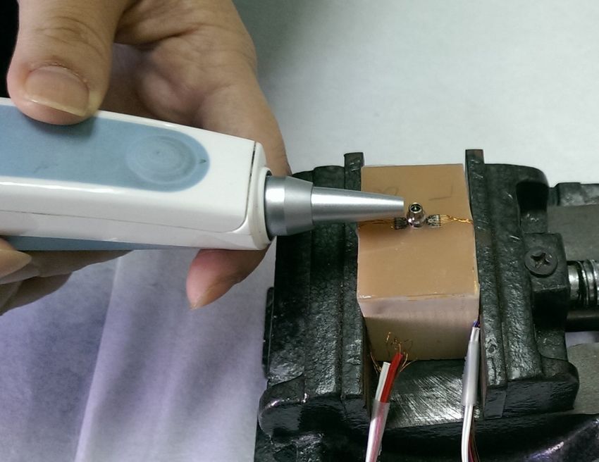
Appl. Sci. 2019, 9, 1998                                                                                                 3 of 9
Appl. Sci. 2019, 9, x FOR PEER REVIEW                                                                                4 of 9

   Appl. Sci. 2019, 9, x FOR PEER REVIEW                                                                          4 of 9

                           Figure 1. The
                           Figure 1. The RP5.0,
                                         RP5.0, RP4.3,
                                                RP4.3, and
                                                       and NP3.5
                                                           NP3.5 implants
                                                                 implants (from right to
                                                                          (from right to left).
                                                                                         left).

     Three specimens of rectangular synthetic trabecular bone (Sawbones model 1522-05, Pacific
Research Laboratories, Vashon Island, WA, USA) were prepared for each implant group. The model
of the trabecular bone with a density of 0.4 g/cm3 and elastic modulus of 759 MPa was employed to
simulate Misch’s type 2 (D2) bone [28,29]. A 2-mm-thick synthetic cortical layer (Sawbones model
3401-02, Pacific Research Laboratories, Vashon, WA, USA) with an elastic modulus of 16.7 GPa was
then attached to the top of the trabecular bone to complete the preparation of the experimental bone
model. The dimensions of each experimental bone model were around 45 mm × 30 mm × 43 mm
(Figure 2).           Figure 1. The RP5.0, RP4.3, and NP3.5 implants (from right to left).

      Figure 2. An experimental bone block with a 2-mm-thick synthetic cortical bone shell was prepared.
      After the implant was placed in the bone block, two rectangular rosette strain gauges were fixed onto
      the crestal cortical region near the buccal (B) and lingual (L) sides of the implant.

         Figure
      Figure  2. 2.
                 An An  experimentalbone
                      experimental     boneblock
                                             block with
                                                   with aa 2-mm-thick
                                                           2-mm-thick synthetic
                                                                        syntheticcortical
                                                                                   corticalbone shell
                                                                                             bone     was
                                                                                                  shell   prepared.
                                                                                                        was  prepared.
         After the  implant  was  placed in the bone block,  two rectangular  rosette strain gauges were
      After the implant was placed in the bone block, two rectangular rosette strain gauges were fixed    fixed onto
                                                                                                                  onto
      thethe crestal
          crestal    cortical
                  cortical    regionnear
                            region   nearthe
                                          thebuccal
                                               buccal(B)
                                                      (B)and
                                                          and lingual
                                                              lingual (L)
                                                                      (L) sides
                                                                          sidesof
                                                                                ofthe
                                                                                   theimplant.
                                                                                        implant.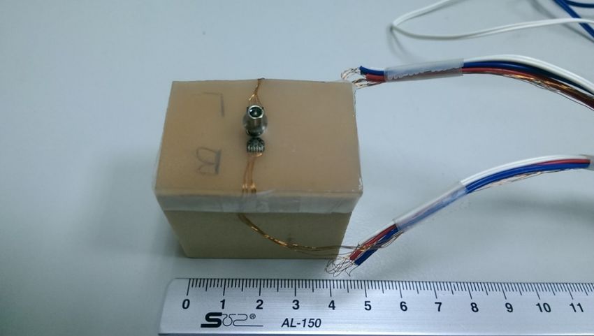
Appl. Sci. 2019, 9, 1998                                                                                       4 of 9

      In order to simulate an immediately loaded implant, the interface between the implant and bone
was prepared for contact only. After inserting the implants into the bone block and connecting titanium
prosthetic abutments to the implants, the device of Periotest (Periotest Classic, Medizintechnik Gulden,
Modautal, Germany) was used to measure the mobility of the implant. Periotest is one of the clinical
noninvasive techniques and is easy to be used; therefore it is favorable for dentists to determine the
initial implant stability after implantation. The process of the measurement was as follows: The tip of
the device was perpendicularly positioned 2 mm from the prosthetic abutments and the instrument
delivered calibrated impacts via a piston to the abutment four times per second for 4 s [30] as seen in
Figure 3. Periotest values (PTVs) were obtained four times in each of four directions (buccal, lingual,
mesial,
Appl. Sci. and
           2019, distal)
                 9, x FORfor each
                          PEER    model.
                               REVIEW                                                              5 of 9

      Figure 3.
      Figure  3. Periotest
                 Periotest values
                           values were
                                  were measured
                                       measured to
                                                 to ensure
                                                    ensure that
                                                           that each
                                                                each implant
                                                                     implant exhibited ideal primary
                                                                             exhibited ideal primary implant
                                                                                                     implant
      stability before performing  the strain gauge analysis.
      stability before performing the strain gauge analysis.

     Two kinds of occlusal loading—a vertical force and a 30degree lateral force—were applied to the
prosthetic abutments by a universal testing machine (JSV-H1000, Japan Instrumentation System, Nara,
Japan) with a custom-made jig as seen in Figure 4. Both kinds of forces had a magnitude of 190 N [31],
and the head speed when applying the loads was 1 mm/min.
     Rectangular rosette strain gauges (FR-1A12L30W05MS, Minebea Company, Tokyo, Japan) were
attached to the crestal cortical region with cyanoacrylate cement (CC-33A, Kyowa Electronic Instruments,
Tokyo, Japan) on both the buccal and lingual sides of the implant as seen in Figure 2. Signals of the
three independent microstrains (εa , εb , and εc ) recorded by the rosette strain gauge were sent to a data
acquisition system (NI CompackDAQ, National Instruments, Austin, TX, USA) and analyzed by the
associated software (LabVIEW SignalExpress 3.0, National Instruments, Austin, TX, USA) as seen in
Figure 4. Each measurement was repeated three times for each specimen, and the maximum (εmax )
and minimum (εmin ) principal microstrains were obtained as follows:
                                                     √
                           εmax = 1/2(εa + εc ) + 1/2 [(εa − εc )2 + (2εb − εa − εc )2 ]                         (1)
                                                     √
                           εmin = 1/2(εa + εc ) − 1/2 [(εa − εc )2 + (2εb − εa − εc )2 ]                         (2)

    Each of the three experimental groups included three experimental specimens. Therefore, there
were a total of nine experimental specimens in this study. For each experimental specimen, five
Appl. Sci. 2019, 9, 1998 5 of 9
measurement values were obtained for statistical analysis. The measured PTV and the peak values
of the principal microstrains of bone under vertical and lateral loading are presented as median ±
interquartile range (IQR) values. The Kruskal-Wallis test was used to compare differences among the
three groups of models. Post-hoc pairwise comparisons were conducted using Mann-Whitney exact
tests with the Bonferroni adjustment, with the significance level set at 0.0167 (=0.05/3). All statistical
Figure 3. Periotest values were measured to ensure that each implant exhibited ideal primary implant
analyses were performed using SPSS (version 19, IBM Corporation, Armonk, NY, USA).
stability before performing the strain gauge analysis.
Figure 4.4.AAvertical
Figure vertical force
force (a) and
(a) and a 30-degree
a 30-degree linguallingual
lateral lateral
force (b)force
were(b) wereasapplied
applied loading as loading
conditions
conditions
by by testing
a universal a universal
machine testing machine
(c). The (c). The
microstrain microstrain
signals signals
were acquired bywere
a dataacquired by system.
acquisition a data
acquisition system.
3. Results
3.1. Periotest
The PTV (Table 1) was lowest for the RP5.0 implant, indicating the highest primary implant
stability, and did not differ significantly between the RP4.3 and RP3.0 implants. All three implant
groups exhibited good primary implant stability, allowing the next stage of the experiment (strain
gauge analysis) to be performed.Appl. Sci. 2019, 9, 1998 6 of 9
Table 1. Periotest values * of the RP5.0, RP4.3, and NP3.5 implants.
Implant PTV
RP5.0 −7.4 a ± 0.3
RP4.3 −6.7 b ± 1.2
NP3.5 −7.2 a ± 0.5
p† 0.012
Data are median ± interquartile range (IQR) values. † Kruskal-Wallis test. * Post-hoc pairwise comparisons were
conducted by the Mann-Whitney exact tests with the Bonferroni adjustment; medians with the same letter a,b are
not significantly different at the 0.0167 (0.05/3) level.
3.2. Strain Gauge Analysis
Under vertical loading, the strain in the bone around the implant was lowest for the RP5.0 implant,
being 36% and 13% lower than for the RP4.0 and NP3.5 implants, respectively. The bone strain did not
differ significantly between the RP4.3 and NP3.5 implants (Table 2).
Table 2. The minimum principal strains * of bone on the buccal and lingual sides for the RP5.0, RP4.3,
and NP3.5 implants.
Analyzed Parameters Microstrain
Loading Implant Buccal Side Lingual Side
Vertical loading RP5.0 a
−1354.56 ± 122.09 −1287.33 a ± 154.08
RP4.3 −1782.62 b ± 248.95 −1836.10 b ± 216.51
NP3.5 −1523.94 b ± 413.68 −1521.28 b ± 669.69
p†Appl. Sci. 2019, 9, 1998 7 of 9
platform also greatly influences the stress applied on the coronal cortical bone in our experiment, and
may also be highly involved in reducing the strain.
A particularly interesting finding was that during vertical loading, the strain on the bone was
higher around the RP4.3 implant than around the NP3.5 implant despite the former having larger
implant and platform diameters. These results indicate that the combined influences of the implant
diameter and the diameter of implant platform in bone strain around an immediately loaded implant
might differ with the type of loading (e.g., vertical vs. lateral), especially for small-diameter implants
given that the smaller-diameter RP3.5 implant showed lower bone strain than the NP4.3 implant under
vertical loading.
In order to avoid the possible confounding factor of individual differences in the characteristics of
human jawbones, the present study used artificial bone specimens as testing samples. Although the
porosities of artificial bone specimens are fairly consistent and their material properties are similar to
those of human bone, further researches should consider performing cadaveric or animal tests. Other
limitations were the dynamic loading [33] and other abutment-implant connection designs [34] for
partial or complete dentures which were not considered in this study. If any further study is performed
in the future, these factors may need to be included for study completeness.
5. Conclusions
While the combined influences of diameter and platform switching concept of titanium dental
implant on bone strain vary with the type of loading (vertical vs. lateral loading), embedding a wider
diameter of implant into bone is obviously beneficial in decreasing the bone strain around immediately
loaded dental implant with platform switching concept.
Author Contributions: Conceptualization, A.Y.-J.W. and H.-L.H.; data curation, H.-L.H.; Formal analysis,
J.-T.H. and H.-L.H.; funding acquisition, A.Y.-J.W. and H.-L.H.; investigation, H.L., A.Y.-J.W. and H.-L.H.;
methodology, J.-T.H. and H.-L.H.; project administration, A.Y.-J.W. and H.-L.H.; resources: J.-T.H. and H.-L.H.;
supervision, A.Y.-J.W. and H.-L.H.; validation, H.L., A.Y.-J.W. and H.-L.H.; writing—original draft, H.L. and
H.-L.H.; writing—review and editing, H.L., A.Y.-J.W. and H.-L.H.
Funding: This research was supported by the following government and academic organizations: Chang Gung
Medical Foundation (CMRPG8E0301), and Ministry of Science and Technology (MOST 105–2628-E-039-001-MY2)
in Taiwan.
Conflicts of Interest: All authors declare that they have no conflict of interest.
References
1. Brunski, J.B.; Puleo, D.A.; Nanci, A. Biomaterials and biomechanics of oral and maxillofacial implants:
Current status and future developments. Int. J. Oral Maxillofac. Implants 2000, 15, 15–46. [PubMed]
2. Griggs, J.A. Dental implants. Dent. Clin. N. Am. 2017, 61, 857–871. [CrossRef]
3. Matarese, G.; Ramaglia, L.; Fiorillo, L.; Cervino, G.; Lauritano, F.; Isola, G. Implantology and periodontal
disease: The panacea to problem solving? Open Dent. J. 2017, 11, 460. [CrossRef]
4. Thoma, D.S.; Mühlemann, S.; Jung, R.E. Critical soft-tissue dimensions with dental implants and treatment
concepts. Periodontol. 2000 2014, 66, 106–118. [CrossRef]
5. Chow, Y.C.; Wang, H.L. Factors and techniques influencing peri-implant papillae. Implant Dent. 2010, 19,
208–219. [CrossRef]
6. Palacci, P.; Nowzari, H. Soft tissue enhancement around dental implants. Periodontol. 2000 2008, 47, 113–132.
[CrossRef]
7. Le Guéhennec, L.; Soueidan, A.; Layrolle, P.; Amouriq, Y. Surface treatments of titanium dental implants for
rapid osseointegration. Dent. Mater. 2007, 23, 844–854. [CrossRef]
8. Huang, H.L.; Hsu, J.T.; Fuh, L.J.; Tu, M.G.; Ko, C.C.; Shen, Y.W. Bone stress and interfacial sliding analysis of
implant designs on an immediately loaded maxillary implant: A non-linear finite element study. J. Dent.
2008, 36, 409–417. [PubMed]Appl. Sci. 2019, 9, 1998 8 of 9
9. Hsu, J.T.; Fuh, L.J.; Lin, D.J.; Shen, Y.W.; Huang, H.L. Bone strain and interfacial sliding analyses of platform
switching and implant diameter on an immediately loaded implant: Experimental and three-dimensional
finite element analyses. J. Periodontol. 2009, 80, 1125–1132. [CrossRef] [PubMed]
10. Ding, X.; Zhu, X.H.; Liao, S.H.; Zhang, X.H.; Chen, H. Implant–Bone Interface Stress Distribution in
Immediately Loaded Implants of Different Diameters: A Three-Dimensional Finite Element Analysis.
J. Prosthodont. 2009, 18, 393–402. [CrossRef]
11. Huang, H.-L.; Hsu, J.-T.; Fuh, L.-J.; Lin, D.-J.; Chen, M.Y. Biomechanical simulation of various surface
roughnesses and geometric designs on an immediately loaded dental implant. Comput. Biol. Med. 2010, 40,
525–532. [CrossRef]
12. Wu, A.Y.-J.; Huang, H.-L.; Hsu, J.-T.; Chee, W. Biomechanical effects of the implant material and
implant–abutment interface in immediately loaded small-diameter implants. Clin. Oral Investig. 2014, 18,
1335–1341. [CrossRef]
13. Wu, A.Y.-J.; Hsu, J.-T.; Chee, W.; Lin, Y.-T.; Fuh, L.-J.; Huang, H.-L. Biomechanical evaluation of one-piece
and two-piece small-diameter dental implants: In-vitro experimental and three-dimensional finite element
analyses. J. Formos. Med. Assoc. 2016, 115, 794–800. [CrossRef]
14. Misch, C.E.; Wang, H.-L.; Misch, C.M.; Sharawy, M.; Lemons, J.; Judy, K.W. Rationale for the application of
immediate load in implant dentistry: Part I. Implant Dent. 2004, 13, 207–217. [CrossRef]
15. Ding, X.; Liao, S.H.; Zhu, X.H.; Zhang, X.H.; Zhang, L. Effect of diameter and length on stress distribution
of the alveolar crest around immediate loading implants. Clin. Implant Dent. Relat. Res. 2009, 11, 279–287.
[CrossRef]
16. Himmlova, L.; Dostálová, T.J.; Kácovský, A.; Konvicková, S. Influence of implasnt length and diameter on
stress distribution: A finite element analysis. J. Prosthet. Dent. 2004, 91, 20–25. [CrossRef]
17. Lazzara, R.; Porter, S. Platform switching: A new concept in implant dentistry for controlling postrestorative
crestal bone levels. Int. J. Periodontics Restor. Dent. 2006, 26, 9–17.
18. Atieh, M.A.; Ibrahim, H.M.; Atieh, A.H. Platform switching for marginal bone preservation around dental
implants: A systematic review and meta-analysis. J. Periodontol. 2010, 81, 1350–1366. [CrossRef]
19. Canullo, L.; Fedele, G.R.; Iannello, G.; Jepsen, S. Platform switching and marginal bone-level alterations: The
results of a randomized-controlled trial. Clin. Oral Implants Res. 2010, 21, 115–121. [CrossRef]
20. López-Marí, L.; Calvo-Guirado, J.L.; Martín-Castellote, B.; Gomez-Moreno, G.; López-Marí, M. Implant
platform switching concept: An updated review. Med. Oral Patol Oral Cir Bucal 2009, 14, e450–e454.
21. Chang, C.-L.; Chen, C.-S.; Hsu, M.-L. Biomechanical effect of platform switching in implant dentistry:
A three-dimensional finite element analysis. Int. J. Oral Maxillofac. Implants 2010, 25, 295–304.
22. Maeda, Y.; Miura, J.; Taki, I.; Sogo, M. Biomechanical analysis on platform switching: Is there any
biomechanical rationale? Clin. Oral Implants Res. 2007, 18, 581–584. [CrossRef]
23. Schrotenboer, J.; Tsao, Y.-P.; Kinariwala, V.; Wang, H.-L. Effect of microthreads and platform switching on
crestal bone stress levels: A finite element analysis. J. Periodontol. 2008, 79, 2166–2172. [CrossRef]
24. Bell, C.; Bell, R.E. Immediate restoration of NobelActive implants placed into fresh extraction sites in the
anterior maxilla. J. Oral Implantol. 2014, 40, 455–458. [CrossRef]
25. Ho, D.S.; Yeung, S.C.; Zee, K.Y.; Curtis, B.; Hell, P.; Tumuluri, V. Clinical and radiographic evaluation of
NobelActiveTM dental implants. Clin. Oral Implants Res. 2013, 24, 297–304. [CrossRef]
26. Babbush, C.A.; Brokloff, J. A single-center retrospective analysis of 1001 consecutively placed NobelActive
implants. Implant Dent. 2012, 21, 28–35. [CrossRef]
27. Irinakis, T.; Wiebe, C. Clinical evaluation of the NobelActive implant system: A case series of 107 consecutively
placed implants and a review of the implant features. J. Oral Implantol. 2009, 35, 283–288. [CrossRef]
28. Chong, L.; Khocht, A.; Suzuki, J.B.; Gaughan, J. Effect of implant design on initial stability of tapered implants.
J. Oral Implantol. 2009, 35, 130–135. [CrossRef]
29. Misch, C.E. Contemporary Implant Dentistry, 2nd ed.; Mosby Co: St Louis, MO, USA, 1999; pp. 372–379.
30. Alsaadi, G.; Quirynen, M.; Michiels, K.; Jacobs, R.; Van Steenberghe, D. A biomechanical assessment of
the relation between the oral implant stability at insertion and subjective bone quality assessment. J. Clin.
Periodontol. 2007, 34, 359–366. [CrossRef]
31. Steiner, M.; Mitsias, M.E.; Ludwig, K.; Kern, M. In vitro evaluation of a mechanical testing chewing simulator.
Dent. Mater. 2009, 25, 494–499. [CrossRef]Appl. Sci. 2019, 9, 1998 9 of 9
32. Baggi, L.; Cappelloni, I.; Di Girolamo, M.; Maceri, F.; Vairo, G. The influence of implant diameter and length
on stress distribution of osseointegrated implants related to crestal bone geometry: A three-dimensional
finite element analysis. J. Prosthet. Dent. 2008, 100, 422–431. [CrossRef]
33. Cervino, G.; Romeo, U.; Lauritano, F.; Bramanti, E.; Fiorillo, L.; D’Amico, C.; Milone, D.; Laino, L.;
Campolongo, F.; Rapisarda, S. Fem and Von Mises Analysis of OSSTEM® Dental Implant Structural
Components: Evaluation of Different Direction Dynamic Loads. Open Dent. J. 2018, 12, 219. [CrossRef]
[PubMed]
34. Lauritano, F.; Runci, M.; Cervino, G.; Fiorillo, L.; Bramanti, E.; Cicciù, M. Three-dimensional evaluation of
different prosthesis retention systems using finite element analysis and the Von Mises stress test. Minerva
Stomatol. 2016, 65, 353–367.
© 2019 by the authors. Licensee MDPI, Basel, Switzerland. This article is an open access
article distributed under the terms and conditions of the Creative Commons Attribution
(CC BY) license (http://creativecommons.org/licenses/by/4.0/).You can also read