Analysis on failure mechanism of CFRP double-tap interference-fit joint
←
→
Page content transcription
If your browser does not render page correctly, please read the page content below
IOP Conference Series: Materials Science and Engineering

PAPER • OPEN ACCESS

Analysis on failure mechanism of CFRP double-tap interference-fit joint
To cite this article: Peng Zou et al 2020 IOP Conf. Ser.: Mater. Sci. Eng. 892 012091

View the article online for updates and enhancements.

                               This content was downloaded from IP address 46.4.80.155 on 30/10/2020 at 14:15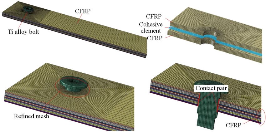
IWMSME 2020                                                                                IOP Publishing
IOP Conf. Series: Materials Science and Engineering 892 (2020) 012091 doi:10.1088/1757-899X/892/1/012091

Analysis on failure mechanism of CFRP double-tap
interference-fit joint

                     Peng Zou1, Hao Chen and Xue Bi
                     Full Scale Aircraft Structural Static/Fatigue Laboratory, AVIC Aircraft Strength
                     Research Institute of China, Xi'an 710065,Shaanxi, China
                     1
                         Email: zoupeng_0625@126.com

                     Abstract. Composite interference-fit joints have attracted much attention because they can
                     effectively reduce the stress concentration around the holes during loading. In this paper, the
                     load-bearing mechanism and strength of a typical double-lap structure under static load are
                     studied through experiment and finite element method. In order to eliminate the influence of
                     bending moment and other factors, a special fixture was designed to study the damage failure
                     mechanism of CFRP interference fit joint under pure tension. The finite element model of
                     CFRP interference fit double lap structure considering both intralaminar and interlaminar
                     damages was established with ABAQUS user subroutine and cohesive element. The damage
                     propagation mechanism during loading process is revealed and the ultimate bearing strength is
                     predicted by comparing the results of experiment and finite element model.

1. Introduction
Carbon fibre reinforced plastic(CFRP) is widely used in aerospace industry because of its high specific
strength, specific stiffness and good fatigue resistance. Although its usage is increasing gradually and
its function is also changing from non-bearing to main-bearing parts, limited to cost and technical
requirements, there are still a large number of mechanical joint structures, especially bolt joint, which
is widely used because of its strong bearing capacity. However, it is also found that the stress
concentration is easily caused during the loading process, which has a negative impact on the bearing
capacity of the structure.
    In order to solve this problem, relevant researchers introduced the metal interference fit style into
the composite ones to reduce local stress concentration and improve bearing capacity. Li j et al. [1]
studied the interface damage behaviour of titanium alloy/CFRP and titanium alloy/titanium alloy
under different interference during the installation of CFRP/Ti alloy interference joint. They pointed
out that the wear particles produced by CFRP damage around the hole have a certain lubricating effect.
Aiming at the phenomenon of hole wall delamination in interference installation process, Zou P et al[2]
established a critical delamination force model based on type I delamination, and predicted the critical
delamination interference percentage. In reference[3], they further considered a variety of damage
modes, and systematically analysed the hole wall quality under the influence of different interference
percentages. During loading process, Liu LQ et al. [4] comprehensively analysed the influence of
interference and bolt preload on the bearing capacity of the structure. Zou P et al. [5] analysed and
predicted the loading failure mechanism and bearing strength of double lap structure. Literatures[6,7]
have studied the fatigue performance of the interference fit structure, found that reasonable
interference can effectively improve the fatigue life. The optimal interference range was recommended.

              Content from this work may be used under the terms of the Creative Commons Attribution 3.0 licence. Any further distribution
              of this work must maintain attribution to the author(s) and the title of the work, journal citation and DOI.
Published under licence by IOP Publishing Ltd                          1
IWMSME 2020                                                                                IOP Publishing
IOP Conf. Series: Materials Science and Engineering 892 (2020) 012091 doi:10.1088/1757-899X/892/1/012091

From the above research, it can be found the relevant research mainly focuses on the selection of
optimal interference by considering the installation, static loading and fatigue processes. Focusing on
the failure mechanism, the research is rare.
    In fact, the bearing mechanism of composite is complex due to anisotropy and weak interlaminar
strength. In the loading process, with the increase of external load, its response shows obvious
nonlinear behaviour. As the damage gradually extends from the local contact area to the whole
extruded surface, and from single-layer plate to whole composite plate, the structure eventually fails.
In this process, the coupling and influence among fibre, matrix and interface are always accompanied,
which makes the prediction of damage and failure difficult. Delamination leads to structural flexural
instability and accelerates structural failure, which cases a significant decrease in the strength of the
structure, especially under compression load. In loading process, the large-area matrix collapse in the
extruded area accelerates the expansion of delamination, and the combination of the two causes the
failure of composite structure[1]. For the interference structure, although it can delay the initiation and
expansion of the damage around the hole to a certain extent, with the increase of load, its damage and
failure are inevitable and become more complex.
    The ultimate purpose of the research is to predict the bearing strength and optimize the interference
based on the understanding of the damage mechanism. Therefore, this paper studied the double lap
interference joint structure through the combination of experiment and simulation method. In order to
eliminate the influence of bending moment, a special fixture was designed to study the damage failure
mechanism of the joint under pure tension. The finite element model considering both intralaminar
and interlaminar damages was established with ABAQUS user subroutine and cohesive element.
While exploring the damage mechanism, the research predicted the effects of interference fit
percentage on the ultimate bearing capacity of the structure.

2. Experimental research

2.1. Specimen preparation
As shown in Figure 1, the test piece is mainly composed of four parts: CFRP plate, 45# steel main
plate, 45# steel side plates and two Ti alloy bolts (1 and 2 respectively). Among them, the main and
side plates as well as Ti alloy bolt 1 constitute the fixture. There are two 6.1mm diameter holes on
each side plate, one of which is used to connect with the main plate to form the fixture, and the other
hole is used to connect with composite piece. In order to avoid the contact between the test piece and
the fixture at the beginning of the test, the thickness of the 45# steel main plate is designed to be 5mm,
while the thickness of the test piece is 4mm. The CFRP plate is placed between the two side plates.
Because the boundary conditions and loading conditions of the test piece in the structure are
completely symmetrical with respect to the middle plane, the damage expansion of the composite
interference fit structure under the pure tensile load can be fully studied through the structure. The
detailed dimensions of the test piece are shown in Figure 1. The laying sequence of composite
materials is [0/±45/90]2s. Single layer thickness is 0.25mm. Material properties are shown in Table 1.
Titanium alloy bolt material is Ti-6Al-4V, material properties are shown in
Table 2.

2.2. Experimental process
The static tensile test was completed on MTS criterion® Series 60 c64.305 static universal hydraulic
testing machine. The test process is shown in Figure 2a). One end of the test piece is clamped by the
chuck of the testing machine, and the other end is connected with the fixture. By applying
displacement load, the force change is recorded. As shown in Figure 2b) in the figure, the elastic
deformation of the two side plates occurs to some extent, which is mainly caused by the expansion
extrusion in the thickness direction of the failed CFRP plate. The interference of the test is set as 0%,
0.4%, 0.8% and 1.2%. Each group of parameters were repeated for three times, and the loading speed
was 2mm/min.

                                                     2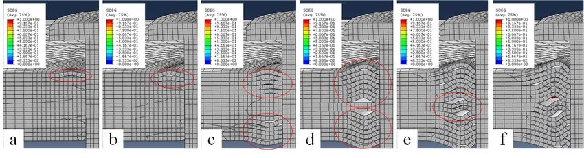
IWMSME 2020 IOP Publishing
IOP Conf. Series: Materials Science and Engineering 892 (2020) 012091 doi:10.1088/1757-899X/892/1/012091
Table 1. Property of T700/BA9916.
Property E1(GPa) E2(GPa) E3(GPa) G12(GPa) G13(GPa) G23(GPa) v12 v13 v23
Value 114 8.61 8.61 4.16 4.16 3 0.3 0.3 0.45
Property Xt(MPa) Xc(MPa) Yt(MPa) Zt(MPa) Yc(MPa) Zc(MPa) S12(MPa) S13(MPa) S23(MPa)
Value 2688 1458 69.5 55.5 236 175 136 136 95.6
Table 2. Property of bolt.
Material Modulus(GPa) Poisson’s ratio Tensile strength(MPa) Yield strength(MPa)
Ti-6Al-4V 112 0.29 931 862
45# steel 210 0.3 625 381
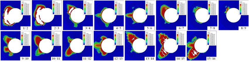
Figure 1. Configuration and size of double lap structure.
Figure 2. Experimental process: a) loading Figure 3. Finite element model.
process, b) specimen.
3. Simulation research
3.1. Finite element model
In order to simplify the model and reduce the calculation requirement, the steel plate fixture is omitted
in the model. The final model is shown in Figure 3, which is mainly composed of two parts: composite
plate and Ti alloy bolt. There are 4320 C3D8R elements in each layer of composite plate, so 16 layers
are composed of 69120 ones. The cohesive elements are embedded between layers, and there are 15
layers of 64800 COH3D8 elements. In order to improve the calculation accuracy, mesh subdivision is
carried out in the area around the hole. The property of the contact pair between bolt shank and hole is
set to limiting slip, and contact relationship is set to normal hard contact and tangential valve contact.
The tangential friction coefficient is set to 0.1. In addition, a general contact is also added to define the
contact relationship among the delaminated plies. In the model, the bolt is fixed, and a reference point
is added and coupling with the right face of the plate. A displacement load is applied to the reference
point.
3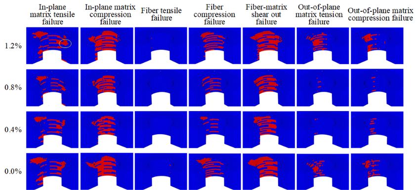
IWMSME 2020 IOP Publishing
IOP Conf. Series: Materials Science and Engineering 892 (2020) 012091 doi:10.1088/1757-899X/892/1/012091
3.2. Constitutive relationships
3.2.1. Intralaminar progressive damage model. The structure is loaded in an obvious 3D stress state,
so the failure process considers both the failure of fibre and matrix in three directions and the shear
failure of the fibre matrix interface. In addition, once the damage occurs, the corresponding properties
also degrades. Therefore, the selection of failure criteria and degradation rule is the key to model
building. Therefore, the modified Hashin failure criterion considering nonlinear shear stress-strain
behaviour of materials[8] is used to predict the structure failure, as shown in Table 3 below.
Table 3. The modified Hashin criteria considering nonlinear shear relationship.
Failure mode criteria
2
e2ft 1 ( 1 0 )
Xt
Fiber failure
(1 0)
2
e 2fc 1
Xc
2
2 2 G0 3124 2132 G130 3134 (1 0)
Fiber-matrix shear out failure e2fs 1 122 120 2 0
X c 2S12 G12 3 S12 2S13 G13 3 S13
4 4
2
2 2122 G120 3124 2 232 G230 3 234 ( 2 0)
2 2 0 2 0
2
emt
Yt 2S12 G12 3 S12 2S23 G23 3 S23
4 4
Matrix tensile failure 2
3 2132 G130 3134 2 232 G230 3 234 ( 3 0)
3 2 0 2 0
2
emt
Zt 2S13 G13 3 S13 2S23 G23 3 S23
4 4
2
2 2122 G120 3124 2 232 G230 3 234 ( 2 0)
2 2 0 2 0
2
emc
Yc 2S12 G12 3 S12 2S23 G23 3 S23
4 4
Matrix compression failure 2
3 2132 G130 3134 2 232 G230 3 234 ( 3 0)
3 2 0 2 0
2
emc
Zc 2S13 G13 3 S13 2S23 G23 3 S23
4 4
With load increase, the material is damaged and the stiffness begins to degrade, which eventually
leads to the decrease of bearing capacity. In this paper, the degradation criterion proposed by Olmedo
A and santiuce C[9] is adopted, as shown in Table 4 below.
Table 4. Property degradation rules.
Failure mode E1 E2 E3 G12 G13 G23 V12 V13 V23
Fibre tension failure ( 1 0) 0.14 0.4 0.4 0.25 0.25 0.2 0 0 0
Fibre compression failure(1 0) 0.14 0.4 0.4 0.25 0.25 0.2 0 0 0
Fibre-matrix shear out failure (1 0) 0.25 0.25 0 0
In-plane matrix tension failure ( 2 0) 0.4 0.4 0.2 0 0 0
In-plane matrix compression failure ( 2 0) 0.4 0.4 0.2 0 0 0
Out- plane matrix tension failure ( 3 0) 0.4 0.4 0.2 0 0 0
Out- plane matrix compression failure ( 3 0) 0.4 0.4 0.2 0 0 0
3.2.2. Interlaminar delamination model. Cohesive element method based on fracture mechanics is
used to simulate delamination damage[10]. The bilinear traction separation constitutive model
characterizing delamination is shown in Figure 4 below. In the loading process, the secondary nominal
stress criterion is used to predict the initiation of mixed mode delamination. When the traction stress
rate meets the following criteria, delamination begins to occur,
2 2 2
tn ts tt (1)
0 0 0 1
tn ts tt
4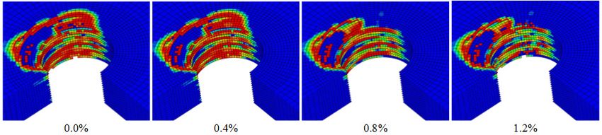
IWMSME 2020 IOP Publishing
IOP Conf. Series: Materials Science and Engineering 892 (2020) 012091 doi:10.1088/1757-899X/892/1/012091
The symbol is Macaulay bracket. The use of this symbol indicates that the compressive load
does not cause delamination expansion, and the effect of the compressive load on the interface layer is
ignored.
Once the delamination initiation is met, the delamination begins to expand between layers. The
interface stiffness also degenerates according to the softening law. With the degradation of the
stiffness, the delamination displacement further increases, and the delamination fracture energy further
consumes until the visible delamination finally occurs. In this paper, energy law[11,12] is used to
define mixed mode delamination failure, as shown in the following formula,
Gn Gs Gt (2)
C C
C 1
Gn Gs Gt
Where Gn , G s and Gt are the instantaneous fracture energy in three directions, respectively. G nC , G sC
and G tC are the critical fracture energy of normal and two tangential stratification under a single mode.
is an empirical parameter, which is used to characterize the coupling degree of three stratified
modes. 1 is obtained here[12-15].
Figure 4. The cohesive double linear constitutive model.
4. Result discussion
4.1. Verification of the simulation model
Failure in the loading process can be regarded as a process of gradual accumulation of compression
damage, which can be divided into three stages: local damage initiation, damage propagation and
structural failure. Although micro damage such as fibre micro buckling and matrix cracking may occur
in the first stage, the effect of these damages on the load displacement curve is relatively small, and
the curve is still linear. When the damage accumulates gradually, a slight load decrease happens and it
5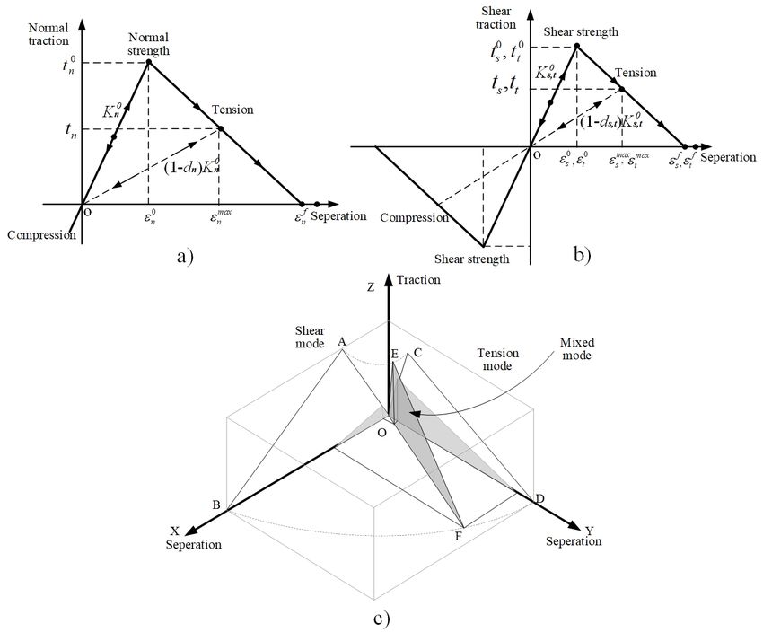
IWMSME 2020                                                                                IOP Publishing
IOP Conf. Series: Materials Science and Engineering 892 (2020) 012091 doi:10.1088/1757-899X/892/1/012091

enters the second stage, the micro damage area further expands. The nonlinear behaviour appears in
the load displacement curve, which occupies most of the time of the structural bearing process. When
the structure reaches the maximum load and causes the ultimate structural failure, the bearing capacity
declines. The load displacement curve can express these three stages and predict the final extrusion
strength. Figure 5 shows the comparison results of finite element and experiment till final failure at 0.8%
interference. The trend and result of finite element and experiment are consistent, the final extrusion
strength is 12.961kN and 13.297kN respectively, and the relative error is 2.6%, which shows the
reliability of finite element model.

       Figure 5. Load-displacement curve.                Figure 6. Effect of interference fit percentage on
                                                                    load-displacement curve.

4.2. Effect of interference fit percentage on load-displacement curve
The load displacement curve and final extrusion strength under different interference (0.0%, 0.4%,
0.8% and 1.2%) are shown in Figure 6. It can be seen from the figure that the stiffness degradation of
0.0% and 0.4% interference is relatively early, while that of 1.2% interference is the latest. The
obvious fluctuation at 1.2% interference indicates that the damage is more complex during loading.
Under
0.8% interference, the bearing strength of the structure reaches the maximum value, followed by 1.2%
interference, and the bearing strength of 0.0% fit is the lowest. The final strength at 0.8% interference
is about 1.24 times that of tight fit(0.0%). It can be seen from the above that, compared with the
clearance fit, an appropriate interference has a certain strength gain capability.

4.3. Damages around the hole

4.3.1. Intralaminar damage analysis. The influence of different interference on the damage around
the hole is shown in Figure 7. It can be seen from the figure that the main failure mode is in-plane
matrix compression failure, while the fibre matrix shear failure and in-plane matrix tensile failure are
also serious. This phenomenon is mainly caused by the poor module and strength of the matrix. The
fibre compression failure is relatively serious at 0° ply, indicating the ply bears lots of load. No fibre
tensile failure occurs. This shows that the fibre bears most of the load, the bearing capacity of the
matrix is weak. The distribution of various damage forms is generally consistent under different
interference percentages. From the scope, the damage of 0.0% and 1.2% interference is relatively
serious, while that of 0.4% and 0.8% interference is relatively light, which is especially obvious in out
of plane matrix tensile and compression failure. Comparing 0.0% interference and 1.2% interference,
the damage of 0.0% is more concentrated and accumulates in a large range in the direction of
extrusion. However, the 1.2% interference is more widely distributed. For in-plane matrix tensile
failure, there is also a certain degree of damage in the opposite direction of the extruded area (marked

                                                     6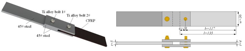
IWMSME 2020                                                                                IOP Publishing
IOP Conf. Series: Materials Science and Engineering 892 (2020) 012091 doi:10.1088/1757-899X/892/1/012091

area in the figure), which is mainly because the larger interference has caused damage in the
installation stage and it maintains or even further expands in the loading stage.

4.3.2. Delamination damage analysis. With the propagation of fibre, matrix and interface damage,
delamination damage also occurs. Compared with intralaminar damage, delamination is more
seriously affected by the thickness direction. According to the damage expansion of delamination
around the hole shown in Figure 8, the damage degree of each layer in the figure is different. The
closer the layer is to the surface of composite plate, the more serious the delamination is, while the
internal layer delamination is relatively less. It can be seen that in the case of lack of lateral restraint
caused by bolt preload, the delamination damage around the hole occurs and expands rapidly in the
area near the surface. In addition, it can be seen from the figure that the damage in and between layers
reaches a relatively large range at this time, but a significant difference from the damage in Figure 7 is
that the direction of each layer has no inevitable one-to-one correspondence with the direction of the
upper and lower layers because the cohesive element is an independent layer between layers.
Delamination mainly occurs in the range of ± 45 degrees in the direction of loading, which is also the
main area of extrusion when the tensile strength is reached.

                 Figure 7. Effect of interference fit percentage on intralaminar damage.

                                Figure 8. Delamination around the hole.

    The comparison of delamination damage under different interference fit percentages is shown in
Figure 9 below. The deleted area in the figure indicates delamination, while the visible red area
indicates delamination initiation criteria has been reached, but delamination has not yet occurred. It
can be seen from the figure that the distribution area of delamination damage is basically the same,
and the distribution range is also basically the same, although the 0.0% interference and 0.4%
interference are relatively large, but the difference is very small. This is mainly because when the load

                                                      7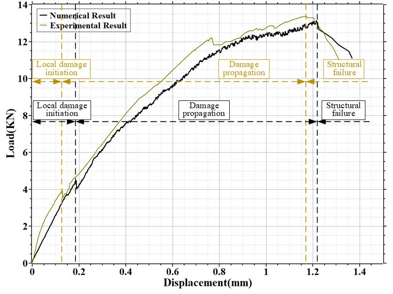
IWMSME 2020                                                                                IOP Publishing
IOP Conf. Series: Materials Science and Engineering 892 (2020) 012091 doi:10.1088/1757-899X/892/1/012091

is large enough, the deformation of the composite hole under load and the difference of contact state
between the pin holes under different interference amount become smaller. When the delamination
damage expands in a large range, it is difficult to see the obvious difference.

              Figure 9. Effect of interference fit percentage on interlaminar delamination.

   The sectional view of delamination expansion is shown in Figure 10, from which it can be seen that
the composite delamination in the extruded area gradually occurs and expands during the tensile
process. Delamination first occurs in the area close to the surface, as shown in figure a and b. With
load increasing, delamination expands along the loading radial direction. Deflection caused by
delamination happens and increases (c and d in the figure), and layers squeeze each other affecting
deflection deformation. When load is large enough, the whole squeezed area suffers from local
deflection instability, resulting in contact or separation areas larger (e, f in the figure). It can be seen
that delamination is easy to occur without lateral restraint. Coupled with local deflection, it further
aggravate the occurrence of intralaminar damage in the layer. In addition, it should be noted that when
damage occurs in the middle layer of the model, elements will not be deleted, so the delamination can
be easily seen. Practically, matrix in the layer can easily separate from the plate and be squeezed into
the interlayer delamination area after being damaged, thus affecting the observation of delamination.

              Figure 10. Delamination propagation in the extruded area around the hole.

4.4. Experimental result analysis
The cutting section of the test piece is shown in Figure 11. The delamination position is basically
consistent with the simulation result. There are a large number of delamination on the upper and lower
surfaces. A certain degree of matrix cracking can be found at the front of delamination, indicating
delamination expansion is closely related to matrix damage, and the two promote each other. In
addition, there are a lot of matrix cracking in the contact area, which results in fibre precipitation and
extrusion. Matrix and fibres are squeezed into the interlaminar region, which not only leads to
delamination, but also expands and bulges along the thickness direction intensifying damage coupling.
In the practical loading process, crushed matrix not only is squeezed into the delamination interface,
but also gathers around the hole wall. They are squeezed by the bolt, changing the contact property
between bolt and hole. These factors cannot be considered in the finite element.

                                                      8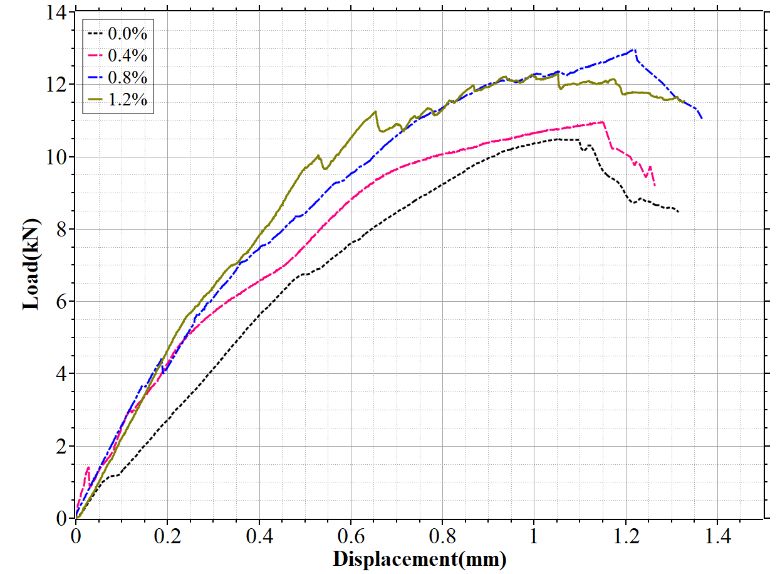
IWMSME 2020                                                                                IOP Publishing
IOP Conf. Series: Materials Science and Engineering 892 (2020) 012091 doi:10.1088/1757-899X/892/1/012091

                             Figure 11. The cutting section of the test piece.

5. Conclusion
In this paper, the static load tensile test and finite element study of the interference fit of CFRP in
double lap structure are carried out. The influence of the interference on damage expansion and
strength of the structure is analysed. The main conclusions are as follows:
    1) For the double lap structure, the stress around the hole is redistributed during the loading process,
and the in-plane damage in the loading area is mainly matrix compression damage, whose distribution
is affected by the lay direction and fibre/matrix strength. At the same time, different degrees of
delamination damage occurs, but the direction of its expansion is not directly related to the direction of
adjacent layers.
    2) The load displacement curve of the double lap structure is obviously nonlinear. For the
composite structure, the interference of 0.8% and 1.2% shows better bearing strength.

Acknowledgments
This work was supported by the Aviation Science Foundation of China (No. 2018ZE23011). The
authors would like to be thankful for the supports.

References
[1] Li J, Li Y, Zhang K, Liu P, Zou P 2015 Interface damage behaviour during interference-fit bolt
        installation process for CFRP/Ti alloy joining structure Fatigue & Fracture of Engineering
        Materials & Structures 38 1359-71
[2] Zou P, Li Y, Zhang K, Liu P, Zhong H 2017 Mode I delamination mechanism analysis on
        CFRP interference-fit during the installation process[J] Materials & Design 116 268-77
[3] Zou P, Li Y, Zhang K, Cheng H, Li J Influence of interference-fit percentage on stress and
        damage mechanism in hi-lock pin installation process of CFRP[J] Journal of Composite
        Materials 0(0) 0021998316689601
[4] Liu LQ, Zhang JQ, Chen KK and Wang H 2014 Combined and interactive effects of
        interference fit and preloads on composite joints Chinese J Aeronaut. 27 716-29
[5] Zou P, Zhang K, Li Y, Liu P, Xie H 2016 Bearing strength and failure analysis on the
        interference-fit double shear-lap pin-loaded composite[J] International Journal of Damage
        Mechanics 1056789516671774
[6] Kim SY, Hennigan DJ, Kim D and Seok CS 2012 Fatigue enhancement by interference-fit in a
        pin-loaded glass fibre-reinforced plastics laminate P I Mech Eng C-J Mec. 226 1437-46
[7] Wei JC, Jiao GQ, Jia PR and Huang T 2013 The effect of interference fit size on the fatigue life
        of bolted joints in composite laminates Compos Part B-Eng. 53 62-8
[8] Camanho PP, Matthews FL 1999 A progressive damage model for mechanically fastened joints
        in composite laminates J Compos Mater 33(24) 2248–80
[9] Olmedo A, Santiuste C, Barbero E 2014 An analytical model for the secondary bending
        prediction in single-lap composite bolted-joints Composite Strucutre 111(1) 354-361

                                                     9
IWMSME 2020 IOP Publishing
IOP Conf. Series: Materials Science and Engineering 892 (2020) 012091 doi:10.1088/1757-899X/892/1/012091
[10] Xiao Y, Ishikawa T 2005 Bearing strength and failure behavior of bolted composite joints (part
I: Experimental investigation) Compos Sci Technol 65(7-8) 1022-31
[11] Zhao L, Gong Y, Zhang J, Chen Y and Fei B 2014 Simulation of delamination growth in
multidirectional laminates under mode I and mixed mode I/II loadings using cohesive
elements Compos Struct. 116 509-22
[12] Chen J-F, Morozov EV and Shankar K 2014 Simulating progressive failure of composite
laminates including in-ply and delamination damage effects Composites Part A: Applied
Science and Manufacturing 61 185-200
[13] Camanho PP, Davila CG, de Moura MF 2003 Numerical simulation of mixed-mode progressive
delamination in composite materials J Compos Mater 37(16) 1415–38
[14] Riccio A, Caputo F, Di Felice G, Saputo S, Toscano C and Lopresto V 2015 A Joint Numerical-
Experimental Study on Impact Induced Intra-laminar and Inter-laminar Damage in
Laminated Composites Appl Compos Mater.
[15] Durao LMP, de Moura MFSF and Marques AT 2008 Numerical prediction of delamination
onset in carbon/epoxy composites drilling Eng Fract Mech. 75 2767-78
10You can also read