DEFINITION OF THE SWE-TRIPLESPAR FLOATING PLATFORM FOR THE DTU 10MW REFERENCE WIND TURBINE - DARUS
←
→
Page content transcription
If your browser does not render page correctly, please read the page content below
Stuttgart Wind Energy (SWE)
 @ Institute of Aircraft Design

 Definition of the SWE-TripleSpar Floating
Platform for the DTU 10MW Reference Wind
 Turbine

 Version Authors
 Frank Lemmer, Florian Amann, Steffen Raach, David Schlipf – SWE, University of
 1.1
 Stuttgart/Germany (USTUTT)
 Frank Lemmer, Florian Amann, Steffen Raach, David Schlipf, Ricardo Faerron Guzmán –
 1.2
 SWE, University of Stuttgart/Germany (USTUTT)
 Frank Lemmer, Steffen Raach, David Schlipf, Ricardo Faerron Guzmán – SWE, University
 2.0
 of Stuttgart/Germany (USTUTT)

Acknowledgements:

The research leading to these results has received partial funding from the European Community’s
Seventh Framework Programme FP7-ENERGY-2012-1-2STAGE under grant agreement No. 308974
(INNWIND.EU).
The research leading to these results has received partial funding from the European Union
Horizon2020 programme under the agreement H2020-LCE-2014-1-640741 (LIFES50+)
Relevant preparatory work for the use of concrete for floating wind substructures was made in the
project KIC-AFOSP (2012-2014)
CREDITS

Version Authors
 Structural design Florian Amann– USTUTT, Dimitrios Manolas, NTUA
 Hydrostatic and linear
 potential flow Frank Lemmer, Florian Amann – USTUTT
 calculations
 Michael Borg – DTU, Frank Lemmer - USTUTT, José Azcona,
 2.0

 Mooring system
 CENER
 Wind turbine
 Frank Lemmer, Steffen Raach, David Schlipf - USTUTT
 controller
 FAST turbine model
 Michael Borg, Henrik Bredmose [1] – DTU
 setup

 2|Page
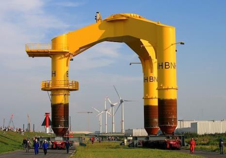
TABLE OF CONTENTS

 CREDITS ........................................................................................................................................... 2

 TABLE OF CONTENTS ...................................................................................................................... 3

 INTRODUCTION ................................................................................................................................ 4

 FAST VERSION ................................................................................................................................. 5

 SYSTEM NATURAL FREQUENCIES .................................................................................................. 6

 TOWER PROPERTIES ....................................................................................................................... 7

 FLOATING PLATFORM STRUCTURAL PROPERTIES ........................................................................ 8

 FLOATING PLATFORM HYDRODYNAMIC PROPERTIES ................................................................ 11
8.1 Hydrostatics ......................................................................................................................... 11
8.2 Hydrodynamics .................................................................................................................... 12
 8.2.1 Linear hydrodynamic damping .................................................................................. 13
 8.2.2 Morison Equation ....................................................................................................... 13

 MOORING SYSTEM PROPERTIES ................................................................................................. 14

 CONTROL SYSTEM PROPERTIES .................................................................................................. 17
10.1 Blade Pitch Controller ......................................................................................................... 17
10.2 Torque Controller ................................................................................................................ 19
10.3 Compilation Framework ...................................................................................................... 19

 ATTACHMENTS .............................................................................................................................. 20

 APPENDIX....................................................................................................................................... 21
 12.1.1 Tripod dimensioning ................................................................................................... 21

 REFERENCES ................................................................................................................................. 22

 3|Page
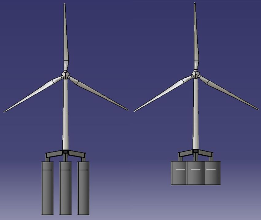
INTRODUCTION

In task 4.3 of the European FP7-project INNWIND.EU, innovative design solutions for large
offshore wind turbine foundations were developed in 2014. The design of the concrete TripleSpar
foundation resulted from the design competition reported in INNWIND.EU deliverable D4.33, [2]
and was further developed within INNWIND.EU in [3].
It was further detailed with the mooring line layout in task 4.1 of the European Horizon2020-
project LIFES50+.
The concept is designed to hold the DTU10MW reference wind turbine, [4], of which all necessary
data for computational simulations can be downloaded from [5]. A FAST v8 [6] model of the
turbine has been developed in LIFES50+, see [7]. A report on the numerical model development
can be found in [8]. Both are part of the model files attached to this document. A detailed
description of the mooring system, especially designed to be tested at the DHI wave basin in
spring 2016 can be found in [9].
In this report, the joint development of this concrete semi-submersible platform is presented as a
public concept, comparable to the OC3 and OC4 concepts for the NREL5MW reference turbine,
see [10] and [11]. It is intended that this concept will be further developed in future projects as a
community-based public development and new versions of the report and the attached files might
be released.
The parameters of the present report are not changed from version 1.0. Minor updates resulting
from detailed structural design can be found inINNWIND.EU deliverable 4.37 Design Solutions for
10MW Floating Offshore Wind Turbines [12]. These changes do not refer to the hull shape, only
the interior mass distribution.

 Figure 1 - TripleSpar.

 4|Page
FAST VERSION

The prepared files were made to run with OpenFAST v1.0.0, which can be downloaded from
https://nwtc.nrel.gov/OpenFAST .

 5|Page
SYSTEM NATURAL FREQUENCIES

The main natural frequencies of the coupled system are listed in Table 1. The frequencies are
calculated assuming a stiff platform.
The tower-top fore-aft mode interferes with the 3-times-per-revolution (3p) frequency, which is a
known problem. The loads, however, are in an acceptable range and dominated by the wave
loading.

 Table 1 - Main system natural frequencies.

 Platform surge 0.005 Hz
 Platform heave 0.06 Hz
 Platform pitch 0.04 Hz
 Tower-top fore-aft displacement 0.4 Hz

 6|Page
TOWER PROPERTIES

The tower of the DTU 10MW reference wind turbine [4] has to be shortened by 25 m due to the
platform height above SWL. The values for the tower base diameter and the mass per length at
the height of 25 m were interpolated as shown in Table 2. The overall properties of the new tower
are listed in Table 3. All elastic properties are adopted from [4] .

 Table 2: Diameter and mass distribution of the tower.

Height [m] Outer diameter [m] Mass per length [kg/m]

 0.000 8.3000 8383.74
 11.500 8.0215 8101.16
 11.501 8.0215 7676.68
 23.000 7.7430 7409.00
 23.001 7.7430 6999.18
 25.000 7.6946 6955.21
 34.500 7.4646 6746.37
 34.501 7.4646 6351.21
 46.000 7.1861 6113.27
 46.001 7.1861 5732.78
 57.500 6.9076 5509.71
 57.501 6.9076 5143.87
 69.000 6.6292 4935.68
 69.001 6.6292 4584.50
 80.500 6.3507 4391.17
 80.501 6.3507 4054.66
 92.000 6.0722 3876.20
 92.001 6.0722 3554.35
 103.500 5.7937 3390.76
 103.501 5.7937 3083.57
 115.630 5.5000 2926.71

 Table 3 - New tower properties.

Tower Property Original tower Shortened tower

Tower base diameter 8.3 m 7.7 m
Length 115.63 m 90.63 m
Mass 628 442 kg 432 955 kg
Center of mass above SWL 47,57 m 63,56 m

 7|Page
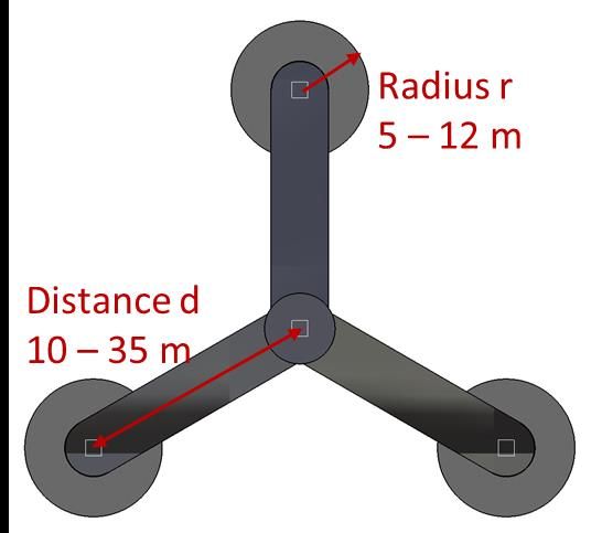
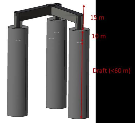
FLOATING PLATFORM STRUCTURAL PROPERTIES

The assumptions for the conceptual design of the platform are based on the findings from the
project AFOSP [13] in which a concrete spar platform for FOWT was conceptually developed.

The concept is a semisubmersible platform with three concrete cylinders. The columns are
connected by a steel tripod which supports the tower of the DTU 10MW reference [4] wind turbine.
The turbine tower has to be shortened by 25 m because of the height of the tripod and the column
elevation above SWL.
The hollow columns are filled with solid ballast. Heave plates were added later on to the design.
The first iteration on heave plates had them made out of steel while the final iteration from
concrete.
Initially, a parametric design was envisioned with variable column spacing, column diameter and
draft, see Figure 2 and Figure 3. In this report, the concept with a draft of about 55m is presented.
Figure 2 shows the platform geometry and the possible range of its dimensions. The concrete spar
elevation above SWL is 10 m to avoid green water loads on the steel structure. The column radii
were considered in the range of 5 to 15 m and the column distance to the vertical centreline
between 10 to 35 m (Figure 2).. An optimization algorithm was used to choose the variable
parameters and later on a detailed design was reported in [12].

 Figure 2 - Platform geometry.

 8|Page
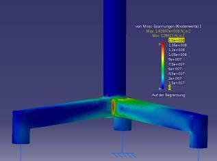
Figure 3 – Two example platforms with a 10MW Turbine.

 Table 4 - Platform structural data.

 Final update (Basis for FAST model)
 Draft (m) 54.464
 Elevation of tower base above
 25
 SWL (m)

 Water displacement (without
 29 205.09
 mooring system) (m3)

Platform Center of mass below SWL (m) 36.0176

 Center of buoyancy below SWL
 27.5381
 (m)

 Platform mass incl. ballast (tn) 28,228

 Ballast mass (tn) 15653.12

 Length (m) 65
 Distance to the center (m) 26

Columns Diameter (m) 15

 Elevation above SWL (m) 10.5
 Mass (tn) 9838.5
 Thickness (m) 0.5
Heave plates Diameter (m) 22.5
 Mass (tn) 1639.3
 Total height (m) 15
Tripod Height outer cylinder (m) 11
 Diameter outer cylinder (m) 5.64

 9|Page
Bar cross-section width(m) 4.6164
 Wall thickness (m) 0.0564
 Mass (tn) 948.36
Tripod- Inclined rod diameter (m) 0.5
Cylinder Inclined rod thickness (m) 0.02
 Horizontal tie diameter (m) 0.5
Connection Horizontal tie thickness (m) 0.02
 Total Mass (tn) 217.5
 Tower height above SWL (m) 119
 Reduced tower length to hub
 94
 height (m)
 Rotor diameter (m) 178.3
 Rotor mass (tn) 228
 Nacelle mass (tn) 446
DTU 10MW Reduced tower mass (tn) 433
RWT I11 about turbine CM (kgm2) 1.613e9
 I22 about turbine CM (kgm2) 1.613e9
 I33 about turbine CM (kgm2) 0.491e9
 Wind turbine mass (kg) 1,106,954
 Wind turbine center of mass
 96.9454
 above SWL (m)
 Concrete density (kg/m3) 2 750
 Steel density (kg/m3) 7 750
Densities
 Ballast density (kg/m3) 2 500
 Water density (kg/m3) 1 025
 Total platform mass (tn) 28828
 Platform I11 without turbine
 1.8674 1010
 (kg/m3)
 Platform I22 without turbine
Moments of 1.8674 1010
 (kg/m3)
Inertia about Platform I33 without turbine
center of 2.0235 1010
 (kg/m3)
mass
 FOWT System I11 (kg/m3) 3.907 1010
 FOWT System I22 (kg/m3) 3.907 1010
 FOWT System I33 (kg/m3) 3.1129 1010

 10 | P a g e
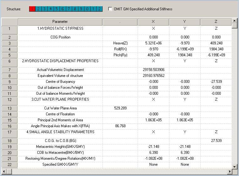
FLOATING PLATFORM HYDRODYNAMIC PROPERTIES

The linear potential flow properties (hydrostatic stiffness, added mass, radiation damping and
wave excitation force coefficient) have been calculated with Ansys Aqwa [14], see Figure 4. The
results were converted to WAMIT format [15] in order to transfer the data to FAST for coupled
time-domain simulations. The propreties have been applied in the Hydrodyn file provided for the
model.

8.1 Hydrostatics

The hydrostatic restoring stiffness is calculated about the point at the intersection of the platform
centreline and the sea-water level (SWL). There is no contribution from gravitational forces and
thus, only the forces from buoyancy and waterplane area are the origin of the rotational
components about the horizontal axes and , see Table 5. The complete linear hydrostatic
results from Ansys Aqwa can be found in Figure 5.
 Table 5 - Main hydrostatic stiffnesses.

 Heave stiffness C33 5.321e6 N/m
 Pitch stiffness C55 -6.199e9 Nm/rad

Were C33 and C55 are the hydrostatic stiffness values of the (33) and (55) elements of the
hydrostatic stiffness matrix. The vertical component is
 33 = ∑ (1)

With the cross-sectional area at the waterplane . Without the gravitational forces, as mentioned
above, the rotational element (55) reads
 55 = ∑ 22 + (2)

with the second moment of area 22 about the horizontal axis, perpendicular to the design
downwind direction, the gravity constant the vertical distance from reference point to the center
of buoyancy , and the platform mass .

 Figure 4 – Mesh in Ansys Aqwa for 1st order radiation and diffraction calculation.

 11 | P a g e
Figure 5 – Aqwa small angle stability (reference point @SWL).

8.2 Hydrodynamics

The hydrodynamic panel code results as added mass, radiation damping and the force-RAO can be
found in Figure 6, Figure 7 and Figure 8.

 Figure 6 – Ansys Aqwa: Added mass.

 12 | P a g e
Figure 7 – Ansys Aqwa: Radiation damping.

 Figure 8 – Ansys Aqwa: Incident wave and diffraction forces.

8.2.1 Linear hydrodynamic damping
The damping resulting from viscous effects is approximated in this version with the diagonal linear
damping matrix with coefficients listed in Table 6.

Table 6 - Linear hydrodynamic damping coefficients.

 Value
Linear damping in surge 1.7 × 10⁵ Ns/m
Linear damping in heave 1.35 × 10⁶ Ns/m
Linear damping in pitch 7.3 × 10⁸ Nms
Linear damping in yaw 1.09 × 10⁸ Nms

8.2.2 Morison Equation
The quadratic hydrodynamic damping of the columns is modelled through the damping term of
Morison Equation. The damping coefficient is approximated as = 0.61.
The hydrodynamic viscous damping from vortex shedding at the heave plates is not yet modelled
in this version. Also, at this stage of the design, no 2nd order hydrodynamic forces such as mean or
slow drift have been implemented.

 13 | P a g e
MOORING SYSTEM PROPERTIES

The mooring system features two upwind lines and one downwind line. The mooring system has
gone through a number of iterations. In the design from CENER, polyester, a common material in
the oil & gas industry, is used in the upper part of the line and a steel chain is selected for the
lower part, which comes in contact with the seabed.

 Table 7 – Mooring line general properties.

 Value
 Fairleads above MSL 10.5 m
 Water depth 180
 Number of lines 3
 Pretension at fairlead 1700 kN
 Fairlead radius position 33.5 m
 Anchor radius position 572.9 m
 Chain nominal diameter 0.180 m
 Chain equivalent 0.324 m
 diameter
 Chain weight/length in 5526.9 N/m
 water
 Chain weight /length in 6350.0 N/m
 air
 Chain length 344 m
 Chain axial stiffness 2.8 E6 kN
 Polyester nominal 0.200 m
 diameter
 Polyester equivalent 0.151 m
 diameter
 Polyester weight /length 60.0 N/m
 in water
 Polyester weight /length 240.0 N/m
 in air
 Polyester length 239 m
 Polyester axial stiffness 4.32 E4 kN

The coefficients of drag are chosen according to section 2.7.1 of the DNVGL-OS-E301 guideline
(DNV-GL, 2015). The values for the fibre rope and stud less chain are corrected regarding the
nominal diameter in order to be in the needed format to be used in Moordyn.

 Table 8 – Mooring line coefficients.

 Section Volume equivalent diameter Traverse Tangential
 of a cylinder having same coefficient of coefficient of
 displacement per unit length drag Cdn drag Cdt
 (-) (m) (-) (-)
 Steel chain 0.324 1.333 0.633
 (studless)
 Polyester (fibre 0.151 2.12 0
 rope)

For the added mass normal a value of 1 is used, according to “Bureau Veritas. NR 493 R02 E.
Classification of Mooring Systems for Permanent Offshore Units. 2002.” The tangential added
mass is set to 0.

 14 | P a g e
Figure 9 –Top view layout of mooring lines.

Table 9 shows the mooring stiffness matrix about SWL in the initial position. Table 10 shows the
linearized stiffness matrix at x=19.57m which corresponds to the position at rated thrust force in
x-direction (horizontal, downwind).

Table 9 - Mooring stiffness matrix about SWL in initial position.

 -8,3283E+04 4,0571E-05 5,8208E-11 5,6087E-03 -2,8465E+06 6,3033E-07
 -3,2045E-05 -8,3283E+04 1,1642E-10 2,8455E+06 0,0000E+00 3,6908E-07
 3,5123E+00 3,7591E-05 -5,7337E+04 4,6545E-03 9,3746E+02 0,0000E+00
 1,2370E-03 2,8436E+06 0,0000E+00 -1,9999E+08 1,4230E-07 3,2756E-04
 -2,8436E+06 1,3773E-03 -3,7253E-09 1,8942E-01 -2,0002E+08 -5,6719E-04
 -5,5507E-07 7,6525E+01 0,0000E+00 -1,5652E+05 0,0000E+00 -2,6931E+08

Table 10 - Mooring stiffness matrix about SWL @ x= 19.57m.

 -7,6888E+04 9,6709E-04 -2,2646E+04 -9,0522E-04 -2,5166E+06 -3,3086E-02
 3,8181E-03 -1,2583E+05 -6,6702E-03 3,9710E+06 4,4467E-09 -9,7468E+04
 -2,2613E+04 7,3521E-04 -5,9279E+04 4,6391E-03 -5,9261E+05 -2,0682E-02
 -1,2496E-01 3,9680E+06 2,1934E-01 -2,8004E+08 1,4230E-07 4,4389E+07
 -2,5152E+06 2,8448E-02 -5,9427E+05 1,1805E-01 -1,6750E+08 -1,2572E+00
 7,8451E-03 -9,6254E+04 -1,3039E-02 -6,7942E+06 -7,1148E-08 -3,0762E+08

The force-displacement and moment-displacement curves can be found in Figure 10 and Figure
11. The upwind and downwind line shapes have been plotted for the rated thrust force in Figure
12, which shows that a reasonable portion of the line is resting on the seafloor for this condition.

 15 | P a g e
Figure 10 – Force-displacement relationship.

 Figure 11 – Moment-displacement relationship.

Figure 12 – Line shape of taut lines and slack line @x=19.57m.

 16 | P a g e
CONTROL SYSTEM PROPERTIES

Due to the floating foundation the DTU10MW baseline controller cannot be used here due to the
“negative damping” problem of the blade-pitch controller for above-rated wind speeds, which has
been reported in the literature, see e.g. [16], [17], [18]

10.1 Blade Pitch Controller

The conceptual controller described here has been developed by the University of Stuttgart,
whereas another conceptual controller has been designed by DTU, which can be downloaded from
[5]. It is designed using a coupled linear model for the above-rated controller and the below-rated
control concept adapted from the NREL 5MW RWT [19]. For the purpose of designing a simple
conceptual controller a single-input-single-output (SISO) Proportional-Integral (PI) controller was
chosen, see Figure 13. It has been designed using a linearised model following the method
reported in [1] [20].

The design strategy is based on the platform pitch mode: Its pole in the closed loop is set such
that its real part is at -0.005 in the left-half plane for all wind speeds. This method results in a
gain-scheduling which ensures the stability of the platform at all operating conditions. With this
platform pitch mode close to the imaginary axes a good performance of the drivetrain mode is
ensured since this mode becomes more stable for increasing gains, which, in turn, lead to
instability of the platform, see Figure 15. Figure 14 shows that for too large gains there appears a
right-half-plane zero next to the platform pitch mode. For more details see [1] [20].

Figure 16 shows the gain scheduling of the controller. The time constant is = 10s, the
generator torque is constant in region 3 (above rated wind speeds).
In the FAST model a linear 2 nd-order actuator model is used with a natural frequency of 1.6Hz and
a damping ratio of 0.8.

 Figure 13 – Conceptual blade-pitch controller.

More in-depth studies on the linear system properties of the TripleSpar and the DTU10MW turbine
and a comparison of different controllers can be found in [21].

 17 | P a g e
Figure 14 – Closed-loop bode plots from wind speed to rotor speed.

 Figure 15 – Closed-loop pole-zero map.

 Figure 16 – Gain scheduling of conceptual controller.

 18 | P a g e
10.2 Torque Controller The torque controller is based on [19]: Region 1 ½ was chosen to be between 5 and 6 rpm rotor speed resulting in 250 to 300 rpm generator speed. For region 2, the optimal tip speed ration was set to 7.2. Region 2 ½ begins at rated torque level. In region 3, the generator torque is hold constant. The resulting nonlinear state feedback function is displayed in Figure 17. 250 2 12 3 200 M G [kNm] 150 2 100 2 +G k I SC 50 0 1 12 1 0 100 200 300 400 500 + G [rpm] Figure 17 – Indirect Speed Controller. 10.3 Compilation Framework The controller has been compiled as Bladed-Style Dynamic Link Library (DLL) to be used with FAST v8. 19 | P a g e
ATTACHMENTS

1 FAST input files
2 WAMIT results
3 Control DLL

 20 | P a g e
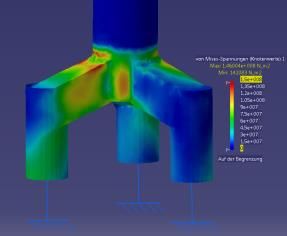
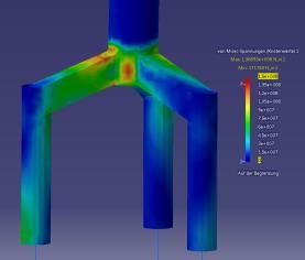
APPENDIX

12.1.1 Tripod dimensioning
The tripod design is based on the transition piece of the Bard “Tripile”, a steel structure for the
bottom fixed Bard 5MW wind turbine, see Figure 2. It consists of three cylinders that are
connected by square-shaped bars. While the bard transition piece is permanently bonded to three
piles by a grout connection, the TripleSpar tripod will be connected to the three concrete spars.

 Figure 18 - Transition piece of the Bard tripile support structure.

The weight of the Bard transition piece is 490 t, see [22], which leads to a wall thickness of about
5 cm.
With this geometry CATIA FEM analysis were performed to upscale the tripod for the 10MW
turbine.
The maximum horizontal force at the tower top of the DTU 10MW turbine is 4 605 kN [4]. Because
the Bard structure was designed for a 5MW turbine, the maximum force at the bard tower was
assumed to be 2 303 kN. This leads to a maximum stress of 139 N/mm. In the next step two
tripods at distances of 10 m and 35 m were designed to match this maximum stress. For the
other considered distances the bar height and wall thickness were interpolated. Table 11 shows
the geometry data for the bard transition piece and the smallest and the largest tripod.
The Tripod geometry has a large influence on the platform cost, because the steel for the structure
is much more expensive than the concrete for the cylinders. It has also an effect on the Platform
COM and its moments of inertia.

 Table 11 Tripod geometry data.

 Bard transition piece Smallest Tripod Largest Tripod

Distance to
 10 m 10 m 35 m
center
Bar height 3m 5m 7m
Wall thickness 0.05 m 0.05 m 0.06 m
Max hor. force 2 303 kN 4 605 kN 4 605 kN
Max stress 139 N/mm 146 N/mm 142 N/mm
Mass 490 t 447 t 1 716 t

 21 | P a g e
REFERENCES

[1] F. Lemmer, W. Yu, D. Schlipf and P. W. Cheng, "Robust gain scheduling baseline controller for
 floating offshore wind turbines," Wind Energy, vol. 23, no. 1, 2020.
[2] F. Sandner, W. Yu, D. Matha, J. Azcona, X. Munduate, E. Grela, S. Voutsinas and A. Natarajan,
 "INNWIND.EU D4.33: Innovative Concepts for Floating Structures," 2014.
[3] J. Azcona, F. Lemmer, F. Amann, S. Raach, D. Schlipf, S. Voutsinas, F. Savenije and D. Kaufer,
 "INNWIND.EU D4.37: Design solutions for 10MW floating offshore wind turbines (to be
 published)," 2016.
[4] C. Bak, F. Zahle, R. Bitsche, T. Kim, A. Yde, L. Henriksen, A. Natarajan and M. Hansen,
 "Description of the DTU 10 MW Reference Wind Turbine".
[5] DTU, June 2016. [Online]. Available: dtu-10mw-rwt.vindenergi.dtu.dk/.
[6] NREL, "NWTC Information Portal (FAST v8)," 13 April 2016. [Online]. Available:
 https://nwtc.nrel.gov/FAST8.. [Accessed 12 May 2016].
[7] M. Borg, M. Mirzaei and H. Bredmose, "LIFES50+ D1.2 Wind turbine models for the design,"
 2016.
[8] M. Borg, "Generic floating substructure configuration and numerical models for wind turbine
 controller tuning in LIFES50+," Kgs. Lyngby, Denmark, 2016.
[9] M. Borg, "Mooring system analysis and recommendations for the INNWIND Triple Spar
 concept," Lyngby, Denmark, 2016.
[10] J. Jonkman and W. Musial, "Final Technical Report, IEA Wind task 23, Subtask 2, Offshore
 Code Comparison Collaboration (OC3)," 2010.
[11] A. Robertson, J. Jonkman, M. M, H. Song, A. Goupee, A. Coulling and C. Luan, "Definition of
 the Semisubmersible Floating System for Phase II of OC4," 2013.
[12] J. Azcona, F. Vittori, U. Schmidt, F. Savenije, G. Kapogiannis, X. Karvelas, D. Manolas, S.
 Voutsinas, F. Amann, F. Lemmer and R. Faerron Guzmán, "Design Solutions for 10MW
 Floating Offshore Wind Turbines," INNWIND:EU, 2017.
[13] C. Molins, D. Matha, F. Sandner, A. Campos, P. Trubat and P. Roca, "KIC-AFOSP D2.2
 Prototype Conceptual Design," Barcelona, 2013.
[14] Ansys, AQWA User Manual, vol. 15317, 2011, pp. 724-746.
[15] Wamit, "User Manual v7.0," 2011.
[16] T. J. Larsen and T. D. Hanson, "A method to avoid negative damped low frequent tower
 vibrations for a floating, pitch controlled wind turbine," Journal of Physics: Conference Series,
 75, 012073. doi:10.1088/1742-6596/75/1/012073.
[17] B. Fischer, "Reducing rotor speed variations of floating wind turbines by compensation of non-
 minimum phase zeros," EWEA 2012, 2012.
[18] G. V. D. Veen, Y. Couchman and R. Bowyer, "Control of floating wind turbines," in Proceedings
 of the American Control Conference ACC, 2012.
[19] J. Jonkman, S. Butterfield, W. Musial and G. Scott, "Definition of a 5-MW Reference Wind
 Turbine for Offshore System Development," Boulder/USA, 2009.
[20] F. Lemmer, S. Raach, D. Schlipf and P. W. Cheng, "Prospects of Linear Model Predictive
 Control on a 10MW Floating Wind Turbine," in Proceedings of the ASME 34th International
 Conference on Ocean, Offshore and Arctic Engineering, St. John's/Canada, 2015.
[21] F. Lemmer, D. Schlipf and P. W. Cheng, "Control design methods for floating wind turbines for
 optimal disturbance rejection (to be published)," Journal of Physics: Conference Series, 2016.
[22] Bard Offshore, 2009. [Online]. Available: http://www.bard-
 offshore.de/uploads/tx_barddocuments/FactSheetBARD5.pdf. [Accessed 06 2015].
[23] R. Laugesen and A. M. Hansen, "Experimental Study of the Dynamic Response of the DTU 10
 MW Wind turbine on a Tension Leg Platform," 2015.

 22 | P a g e
You can also read