Nonintrusive Installation of the TMR Busbar DC Current Sensor
←
→
Page content transcription
If your browser does not render page correctly, please read the page content below
Hindawi
Journal of Sensors
Volume 2021, Article ID 8827131, 10 pages
https://doi.org/10.1155/2021/8827131

Research Article
Nonintrusive Installation of the TMR Busbar DC Current Sensor

 X. P. Xu ,1 T. Z. Liu ,1 M. Zhu ,2 and J. G. Wang 2

 1
 The School of Mechatronic Engineering and Automation, Shanghai University, Shanghai 200044, China
 2
 Sinomags Technology Co., Ltd., Ningbo 315200, China

 Correspondence should be addressed to T. Z. Liu; liutz09@126.com

 Received 16 September 2020; Revised 20 December 2020; Accepted 25 January 2021; Published 8 February 2021

 Academic Editor: Heinz C. Neitzert

 Copyright © 2021 X. P. Xu et al. This is an open access article distributed under the Creative Commons Attribution License, which
 permits unrestricted use, distribution, and reproduction in any medium, provided the original work is properly cited.

 In recent years, new energy vehicles, photovoltaic power stations, communication base stations, energy storage systems, and other
 power electronic systems have developed rapidly. The development of these systems has the trend of continuously increasing the
 power density per unit area, reducing the system volume, and continuously increasing using the busbars. More and more new
 current sensors will be used in these systems and play a key role. Traditional current sensor cannot meet the development trend
 of power electronic systems due to their large size and high cost. In this paper, a new small coreless tunnel junction
 magnetoresistance (TMR) busbar dc current sensor adopted differential scheme which improves the sensor’s anti-interference
 ability that is designed. The current sensor adopts an open-closed structure for easy nonintrusive installation. Four TMRs which
 adopted differential structure are placed on the edges of the busbar. The peak current measurement range is ±600 A, the rated
 current measurement range is ±300 A, and the supply voltage is 5 V.

1. Introduction the external magnetic field [7–9]. A busbar with an amphi-
 theater hole is shown [10], and an AMR busbar current sen-
Due to its noncontact isolation measurement, high precision, sor is described [6]. Circular sensor array is also a commonly
and low cost [1, 2], current sensors are widely used in power used measurement method. Its accuracy is less dependent on
electronic systems, such as photovoltaics, wind power, and the position of the conductor, and it has better resistance to
electric vehicles, and the use of current sensors has increased external magnetic field interference [11, 12]. The disadvan-
year by year. A magnetic field is generated by the measured tage of circular arrays is that they are too large. In previous
current. The magnetic field can be measured using different research literature, each magnetic sensing device is separately
sensor technologies including Hall effect sensor, magnetic amplified and measured, and then the measured current
fluxgate, and magnetoresistance (MR) sensor. The MR sen- value is obtained by comprehensive calculation and fitting
sors have grabbed the attention of researchers in recent years [13]. The existing method is complicated, and the cost is
due to their high sensitivity. The latest research in this field high. Since the TMR itself is a magnetoresistance device,
mainly includes anisotropic magnetoresistance (AMR), giant the magnetoresistances can be connected in parallel. In this
magnetoresistance (GMR), and TMR. Hall, AMR, GMR, and paper, four TMRs are directly connected in parallel.
TMR have been used in current sensors [3–6]. Hall has the The TMR sensor is a thin film element in which a barrier
inherent defects of low sensitivity, high power consumption, layer consisting of a thin insulator is sandwiched between
and poor linearity. Although the sensitivity of AMR and two ferromagnetic layers (free layer/pin layer). Due to the
GMR is much higher than that of hall, their linear range is wave-like nature of electrons, electrons in the ferromagnetic
narrow. Compared with hall, AMR, and GMR, TMR has bet- layer can tunnel through the insulator layer, and the possibil-
ter temperature stability, higher sensitivity, lower power con- ity of tunneling through is related to the magnetization of pin
sumption, and better linearity. The conventional busbar and the free layer. The magnetization direction of the pin
current sensor with differential structure adopts a pair of hall layer is fixed, and the magnetization direction of free layer
sensors on the conductor surface, which partially suppresses changes with the direction of the external magnetic field.
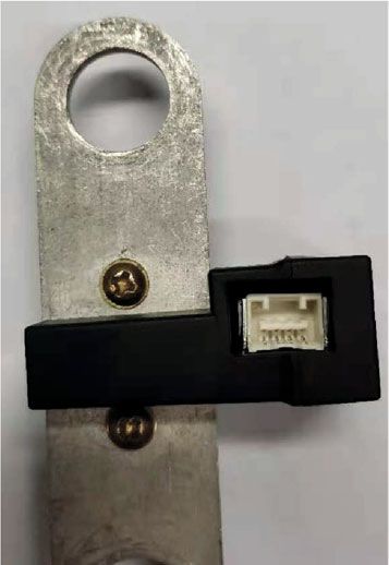
2 Journal of Sensors

 busbar dc current sensor
 B2 B1
 TMR2 y TMR1
 b I busbar Iex
 x
 TMR3 a TMR4 Interference busbar
 B3 B4

 D

 (a) (b)

 Figure 1: (a) Current sensor photo. (b) Structure of the busbar current sensor with the interference busbar.

 R
 Rmax

 Free layer
 Barrier layer
 A
 Pinned layer
 Antiferromagnet

 Rmin B

 (a) (b)
 VCC

 R1 R4

 V+ V–

 R2 R3

 GND
 (c)

 Figure 2: (a) Structure of an MTJ. (b) Typical response curve of a TMR sensor. (c) Wheatstone bridge circuit of TMR.

When the direction of magnetization of the pin layer is as shown in Figure 2(a). There is a thin layer of insulation
parallel to that of the free layer, the resistance is minimal, that can be tunneled by electrons between the magnetic
since the electron tunneling is the largest and vice versa. layers. This structure is called a magnetic tunnel junction
Obviously, the TMR element has a sensitive orientation (MTJ). When the free layer is magnetically aligned with
due to pin layer magnetization fixation. In this paper, the pinned layer, electrons are more likely to pass through
the sensitive direction of all TMR chips is parallel to the the barrier layer [14, 15].
surface and set to the x direction (Figure 1). The structure Therefore, the resistance (R) of the sensor depends on the
of the TMR sensor is a magnetic multilayer film material, external magnetic flux field (B), as shown in Figure 2(b). In
Journal of Sensors 3

 G A/m2
 ×107
 250 1
 240
 230
 220
 210
 200
 190
 180
 DC 170
 160
 150
 140
 130
 120
 110
 90
 80
 70
 60
 50
 40
 30
 20
 10
 0 1

 Figure 3: 600 A current density at busbar and magnetic flux density near busbar.

 VCC VCC
 B2 B1
 R21 R24 R11 R14
 V2+ T V2– V1+ T V1–
 M M
 R22 R R23 R12 R R13
 2 1
 S S
 TMR2 TMR1
 Bex – VOUT
 busbar
 +
 Bex
 TMR3 TMR4 PGA
 S S
 R33 T R32 R43 T R42
 V3– M V3+ V4– M V4+
 R R44 R R41
 R34 3 R31 4
 B3 B4
 VCC VCC

 Figure 4: Circuit diagram of current sensor module.

Figure 2(c), the TMR chip consists of Wheatstone bridge and ment in different ranges. The use of nonmagnetic core
has a good temperature characteristics and anticommon- solution can effectively reduce the volume and weight. Dif-
mode signal interference. The bridge circuit contains four ferential structure current sensors are used to partially
resistances as shown. V+ represents the forward half-bridge suppress the external magnetic field interference and
terminal output of TMR, and V- represents the negative half- improve the test accuracy. We present a new small volume
bridge terminal output of TMR. The voltage between V+ and current sensor with the characteristics of the nonintrusive
V- is proportional to the adjacent magnetic flux density, also installation. The supply voltage is 5 V, the rated current
to the current under measurement. measurement range is ±300 A, and the peak current
 The new type of current sensor proposed in this paper measurement range is ±600 A, corresponding to 2:5 ± 2 V
adopts the TMR array, with flexible differential structure output at ±600 A dc current. It uses a differential tech-
and no magnetic core, and is suitable for current measure- nique based on tunnel junction magnetoresistance (TMR)
4 Journal of Sensors

 VCC VCC
 B1 B1
 R11 R14 R21 R24
 V1+ – VOUT V2+ V2–
 – VOUT
 V1–
 R12 R13 + R22 R23 +
 PGA PGA

 (a) (b)
 VCC VCC
 –B1 –B1
 R31 R34 R41 R44
 V3+ V3– – VOUT V4+ V4– – VOUT
 R32 R33 + R42 R43 +
 PGA PGA

 (c) (d)

 Figure 5: TMR and PGA connection.

 VCC VCC VCC VCC VCC
 B1 B1 B1 B1 B1
 R1 R4 R1 R4 R4 R4
 + = =
 V+ V– V+ V– V– V–
 R2 R3 R2 R3 R3 R3

 (a) (b)
 VCC VCC VCC
 B1 B1 B1 B1
 R1 R4 R1 R4
 V+ + =
 V– V+ V–
 R2 R3 R2 R3

 (c)

 Figure 6: The equivalent circuit of TMR in the magnetic flux density.

 VCC
 VCC Bex Bex
 B1 RA1 RA4
 RA1 RA4 VE+ – VOUT
 VOUT VE–
 VA+ VA– –
 RA2 RA3 +
 RA2 RA3 +
 PGA
 PGA

 Figure 8: The equivalent circuit of the busbar current sensor in the
 Figure 7: The equivalent circuit of the busbar current sensor. external magnetic flux density.

 2. Sensor Design
technology placed on the surface of the busbar. The cur-
rent sensor module is consisted of TMR chips, program- 2.1. Busbar Current Sensor. The TMR and PGA chips are sol-
mable gain amplifier (PGA). Because of busbar’s skin dered on the printed circuit board (PCB). The four TMR
effect, which is relatively complex, this paper focuses on chips are connected in differential mode and then connected
dc current measurement, not AC current measurement. to the PGA input port. PGA is used to adjust the gain and
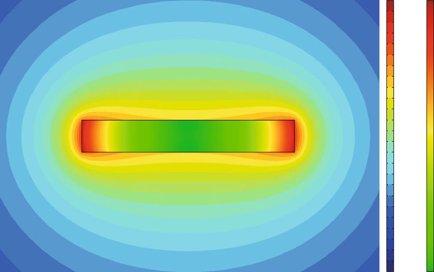
Journal of Sensors 5

temperature characteristics of the current sensor. For the sists of four resistors connected as a Wheatstone bridge. Each
current sensor, TMR and PGA used in this paper manufac- TMR chip is connected to PGA through the V + terminal
tured by Sinomags Technology Co., Ltd. in China. We design and V − terminal. Ideally, the sensitivity of TMR1, TMR2,
and test the performance of TMR and PGA and give the test TMR3, and TMR4 is the same and parallel to the x-axis.
data of the current sensor in this paper. The V + terminals of TMR1, TMR2, TMR3, and TMR4 are
 Figure 1 shows the photo of the current sensor and the connected to the IN+ terminal of the PGA. The V- terminals
schematic diagram of the differential structure of the module. of TMR1, TMR2, TMR3, and TMR4 are connected to the IN-
The V + terminals of TMR1, TMR2, TMR3, and TMR4 are terminal of the PGA. B1 , B2 , B3 , and B4 represent the mag-
connected with the IN+ terminal of PGA. The V − terminals netic flux density at the positions of TMR1, TMR2, TMR3,
of TMR1, TMR2, TMR3, and TMR4 are connected with the and TRM4, respectively. B2 and B1 have the same value, in
IN- terminal of PGA. This connection forms a differential the same direction. B3 and B1 are equal and opposite. B4
structure. The use of a differential structure has the advan- and B1 are equal and opposite. Bex represents the external
tage of being resistant to external magnetic fields. I is the magnetic flux intensity. S represents the sensitivity of the
measured busbar current, and the cross-sectional area TMR chip.
(a × b) of the busbar is 20 mm × 3 mm, whose length is
80 mm, and the vertical distance (y-axis) between the TMR B 1 = B 2 = B3 = B 4 : ð2Þ
and the center of the busbar is 4.8 mm, which is determined
by the thickness of the parts. The size of the busbar is 20 The equivalent circuit of each TMR and PGA connection
mm × 3 mm × 80 mm, and the TMR sensitivity direction is is shown in Figure 5.
parallel to the x-axis in Figure 1. (0, 0) is the busbar center Ideally, the resistance values of the four resistors of TMR
coordinate. The coordinates of four TMR chips are (6.3, chips in the same wafer are equal. The same goes for the
4.8), (-6.3, 4.8), (-6.3, -4.8), and (6.3, -4.8). I ex is the interfer- sensitivity.
ence busbar current. The distance (D) between the centers of
two busbars with the same size is 60 mm, which is three times R11 = R12 = R13 = R14 = R21 = R22 = R23 = R24
the busbar width. ð3Þ
 = R31 = R32 = R33 = R34 = R41 = R42 = R43 = R44 :
 The sensitivity of TMR is typically 0.1 mV/V/Gs, and
the saturation magnetic field is 200 Gs. In the 200 Gs mag-
netic field range, the TMR chip has good linearity, beyond Each V + and V − output for each TMR chip is shown in
200 Gs, and the TMR chip output tends to be saturated. equations (4) to (12).
When the measured current is 600 A, the working mag-
 V CC S
netic field of the sensor is within 200 Gs (Figure 3); so, V 1+ = + V CC B1 , ð4Þ
the current sensor has good linearity. Four TMR chips 2 2
are connected in a differential mode and mounted on
 V CC S
the sides of the PCB. The current sensor adopts an V 1− = − V CC B1 , ð5Þ
open-closed structure for easy installation. The sensor is 2 2
installed at busbar via 2 set screws. V 1 +−V 1 − = V CC B1 S, ð6Þ
2.2. Magnetic-Field Analysis. For the busbar whose cross- V CC S V S
section is rectangular, a and b are the length and width dimen- V 2+ = + V CC B2 = CC + V CC B1 , ð7Þ
 2 2 2 2
sions of the cross-section of the busbar. Current I is passed
through the busbar. Bx represents the magnetic flux density V CC S V S
 V 2− = − V CC B2 = CC − V CC B1 , ð8Þ
parallel to the TMR sensitivity at coordinates (f x, f y) in 2 2 2 2
Figure 1. According to Maxwell equation, the magnetostatic
 V CC S V S
equation can be written as equation (1). V 3+ = + V CC B3 = CC + V CC B1 , ð9Þ
 2 2 2 2
 ð a/2 ð b/2
 2I fy −y V CC S V S
Bx = qffiffiffiffiffiffiffiffiffiffiffiffiffiffiffiffiffiffiffiffiffiffiffiffiffiffiffiffiffiffiffiffiffiffiffiffiffiffiffiffi · qffiffiffiffiffiffiffiffiffiffiffiffiffiffiffiffiffiffiffiffiffiffiffiffiffiffiffiffiffiffiffiffiffiffiffiffiffiffiffiffi dxdy: V 3− = − V CC B3 = CC − V CC B1 , ð10Þ
 −a/2 −b/2 2
 ð f x − xÞ + ð f y − yÞ 2
 ð f x − xÞ2 + ð f y − yÞ2 2 2 2 2

 ð1Þ V CC S V S
 V 4+ = + V CC B4 = CC + V CC B1 , ð11Þ
 2 2 2 2
 COMSOL software was used for finite element simulation. V CC S V S
Figure 3 shows 600 A current densities at the busbar and the V 4− = − V CC B4 = CC − V CC B1 : ð12Þ
 2 2 2 2
magnetic flux density near busbar. Take the magnetic flux
density of B1 and B2 in the positive direction. Referring to V 1 + , V 2 + , V 3 + , and V 4 + are connected in parallel
equation (1), when current I is 600 A, the absolute magnetic and then connected to the IN+ of the PGA. V 1 − , V 2 − ,
flux density is show in Figure 3. V 3 − , and V 4 − are connected in parallel and then
 connected to the IN- of the PGA.
2.3. Sensor Circuit Design. The equivalent circuit diagram of The equivalent circuit of TMR in the magnetic flux
the current sensor is shown in Figure 4. The TMR chip con- density is shown in Figure 6.
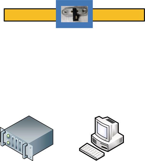
6 Journal of Sensors

 TMR current sensor

 PC

 DC High-low
 I PGA output current temperature
 source test
 ADC+MCU+RS485 chamber

 RS232

 Current source Control computer
 (a) (b)

 Data acquisition card

 (c)

 Figure 9: (a) Diagram of the measurement system. (b) Test device. (c) Busbar current sensor test.

 Table 1: Test instruments.

Device Model Manufacturer
DC current source XF30ZA-1 K Tsinghua Science and Technology Development Co., Ltd.
Power supply GPD-3303S Guwei Electronics Co., Ltd.
Multimeter DMM4050 Tektronix
PC RK-610 ADLINK
Data acquisition card SMDAQ-6000 Sinomags Technology Co., Ltd.
High-low temperature RGDJ-500 Surui Test Equipment Co., Ltd.

 The equivalent circuit of the busbar current sensor is B1 represents the magnetic flux density generated by the
shown in Figure 7. measured current I at TMR1 according to equation (1). K I
 is the coefficient between B1 and current I.
 RA1 = R11 //R21 //R31 //R41 , ð13Þ

 RA2 = R12 //R22 //R32 //R42 , ð14Þ V OUT = ðV A +−V A − ÞK A : ð20Þ

 RA3 = R13 //R23 //R33 //R43 , ð15Þ
 K A is the magnification of PGA.
 RA4 = R14 //R24 //R34 //R44 , ð16Þ Equations (4)–(6) and (17)–(20) can be calculated to
 ð17Þ obtain equation (21). The V OUT of the busbar current sensor
 V A + = V 1 +//V 2 +//V 3 +//V 4 +,
 is shown in equation (21).
 V A − = V 1 −//V 2 −//V 3 −//V 4 −, ð18Þ

 B1 = I · K I : ð19Þ V OUT = ðV 1 +−V 1 − ÞK A = V CC B1 SK A = V CC ISK I K A : ð21Þ
Journal of Sensors 7

 5

 4.5

 4

 Current sensor Vout (V)
 3.5

 3

 2.5

 2

 1.5

 1

 0.5

 0
 −600 −500 −400 −300 −200 −100 0 100 200 300 400 500 600
 Current (A)

 (a)
 1

 0.8

 0.6
 Current sensor linearity error (%)

 0.4

 0.2

 0

 −0.2

 −0.4

 −0.6

 −0.8

 −1
 −600 −500 −400 −300 −200 −100 0 100 200 300 400 500 600
 Current (A)

 (b)

Figure 10: (a) 600 A dc peak current I-V characteristics of the current sensor. (b) Relative accuracy of current sensor within 600 A dc peak
current at 25°C.

 2

 1.5

 1
 Noise RMS of sensor (mV)

 0.5

 0

 −0.5

 −1

 −1.5

 −2
 0 10 20 30 40 50
 Time (s)

 Figure 11: Noise RMS of the current sensor.
8 Journal of Sensors

 2.51

 Offset in the full temperature zone (V)
 2.5

 2.49

 2.48
 −40 −20 0 20 40 60 80 100

 (a)
 1

 0.8

 0.6
 Percentage of sensitivity change (%)

 0.4

 0.2

 0

 −0.2

 −0.4

 −0.6

 −0.8

 −1
 −40 −20 0 20 40 60 80 100

 (b)
 1

 0.8
 Current sensor relative accuracy (%)

 0.6

 0.4

 0.2

 0

 −0.2

 −0.4

 −0.6

 −0.8

 −1
 0 50 100 150 200 250 300
 Current (A)

 (c)

Figure 12: (a) Offset in the full temperature zone. (b) Percentage of sensitivity change in the full temperature zone relative to 25°C. (c) Relative
accuracy of current sensor in the full temperature zone relative to 25°C.
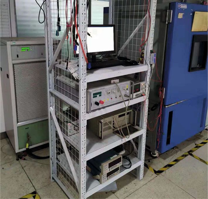
Journal of Sensors 9

 The equivalent circuit of the busbar current sensor in the 4. Conclusions
external magnetic flux density is shown in Figure 8.
 This paper designs a new type of small volume dc current
 V S sensor, which has the characteristics of small volume, flexible
 V E + = CC + V CC Bex , ð22Þ installation, and high precision. The current sensor adopts a
 2 2
 new differential combination scheme, which has good linear-
 V CC S ity and anti-interference ability. The current sensor adopts an
 V E− = + V CC Bex , ð23Þ open-closed structure for easy nonintrusive installation.
 2 2
 Compared with the traditional magnetic current sensor and
 V OUT = ðV E +−V E − ÞK A = 0: ð24Þ ring array sensor, the new sensor has a smaller volume. The
 size of the current sensor can be adjusted flexibly according
 Therefore, it can be concluded from equation (24) that
 to the size of the busbar. The relative accuracy of the current
under the constant external magnetic field interference, the
 sensor in the full temperature range is within ±1%. It is very
output of the current sensor does not change, which meets
 suitable for the dc busbar power system and has a broad
the requirement of the resisting external constant magnetic
 application prospect.
field interference.
 In Figure 1, when the measured busbar is passed with
600 A current without an external interference busbar, it Data Availability
can be obtained from Figure 3 that the equivalent differential The data that support the findings of this study are available
magnetic field strength of the current sensor is 19.52 Gs. from the corresponding author upon reasonable request.
When the measured busbar and the interference busbar with
the same size are passed with 600 A current in the same direc-
tion, the equivalent differential magnetic field strength of the
 Conflicts of Interest
current sensor is 19.80 Gs. The interference error of the The authors declare that they have no conflicts of interest.
current sensor is 1.4%. When D takes other values, the same
method can be used for analysis and calculation. Acknowledgments
3. Results The authors would like to thank H.Y. Chen, X.G. Yao, J.M.
 Bai, K. Tan, C. Gao, and J.J. Feng. This work went well under
The maximum magnetic flux density generated by the dc their help.
600 A current near TMR is less than 200 Gs, in the good
working linear range of TMR.
 References
 Figure 9 shows the measurement system which includes
current source, power supply, multimeter, PC, and data [1] C. Xiao, L. Zhao, T. Asada, W. G. Odendaal, and J. D. van
acquisition card which includes microcontroller unit Wyk, “An overview of integratable current sensor technolo-
(MCU), analog-to-digital converter (ADC), RS232, and gies,” in 38th IAS Annual Meeting on Conference Record of
RS485. The MCU is S9S08DZ60F2MLH made by NXP semi- the Industry Applications Conference, pp. 1251–1258, Salt Lake
conductors, and the ADC is AD7194BCPZ made by Analog City, UT, USA, USA, 2003.
Devices, Inc. The dc current source is XF30ZA-1 K, which [2] S. Ziegler, R. C. Woodward, H. H. C. Iu, and L. J. Borle, “Cur-
is manufactured by Tsinghua Science and Technology Devel- rent sensing techniques: a review,” IEEE Sensors Journal, vol. 9,
opment Co., Ltd., China, with a typical accuracy of ±0.02%, no. 4, pp. 354–376, 2009.
which can meet the requirements of current sensor testing [3] H. Zhang, F. Li, H. Guo, Z. Yang, and N. Yu, “Current mea-
in Table 1. surement with 3-D coreless TMR sensor array for inclined
 Figure 10 shows the I-V characteristic, and the linearity conductor,” IEEE Sensors Journal, vol. 19, no. 16, pp. 6684–
error of the current sensor is less than ±1% at 25°C. 6690, 2019.
 Using the default configuration of the multimeter [4] I. Jedlicska, R. Weiss, and R. Weigel, “Increasing the measure-
 ment accuracy of GMR current sensors through hysteresis
DMM4050, a sampling period of 0.5 s, sampling for 50 s, to
 modeling,” in 2008 IEEE International Symposium on Indus-
test the noise of the current sensor. Figure 11 shows the noise trial Electronics, pp. 884–889, Cambridge, UK, 2008.
RMS (root mean square) of the current sensor that is about
 [5] L. Cristaldi, A. Ferrero, M. Lazzaroni, and R. T. Ottoboni, “A
±1 mV. The good noise characteristic of the sensor is the linearization method for commercial hall-effect current trans-
guarantee of the good accuracy of the sensor. ducers,” IEEE Transactions on Instrumentation and Measure-
 Figure 12(a) shows the offset of the current sensor in the ment, vol. 50, no. 5, pp. 1149–1153, 2001.
full temperature zone. The change of offset in the full temper- [6] Z. Zhenhong, O. Syuji, A. Osamu, and K. Hideto, “Develop-
ature zone relative to 25°C is not more than ±10 mV. The ment of the highly precise magnetic current sensor module
sensitivity change in the full temperature zone relative to of +/-300 A utilizing AMR element with bias-magnet,” IEEE
25°C is less than ±1% in Figure 12(b). Figure 12(c) shows Transactions on Magnetics, vol. 51, no. 1, 2015.
the relative accuracy of current sensor relative to 25°C in [7] “CSA-1V Melexis Datasheet,” June 2013, https://www.melexis
the full temperature zone. The relative accuracy of the .com.
current sensor in the full temperature range is within ±1%. [8] M. Blagojevic, U. Jovanovic, I. Jovanovic, D. Mancic, and R. S.
So, the current sensor has good temperature characteristics. Popovic, “Coreless open-loop current transducers based on
10 Journal of Sensors

 hall effect sensor CSA-1V,” Facta Universitatis Series: Electron-
 ics and Energetics, vol. 29, no. 4, pp. 489–507, 2016.
 [9] M. Blagojevic, U. Jovanovic, I. Jovanovic, D. Mancic, and R. S.
 Popovic, “Realization and optimization of bus bar current
 transducers based on Hall effect sensors,” Measurement Sci-
 ence and Technology, vol. 27, no. 6, p. 065102, 2016.
[10] P. Ripka, M. Pribil, V. Petrucha, V. Grim, and K. Draxler, “A
 fluxgate current sensor with an amphitheater Busbar,” IEEE
 Transactions on Magnetics, vol. 52, no. 7, pp. 53–58, 2016.
[11] L. Di Rienzo and Z. Zhang, “Spatial harmonic expansion for
 use with magnetic sensor arrays,” IEEE Transactions on Mag-
 netics, vol. 46, no. 1, pp. 53–58, 2010.
[12] R. Weiss, R. Makuch, A. Itzke, and R. Weigel, “Crosstalk in cir-
 cular arrays of magnetic sensors for current measurement,”
 IEEE Transactions on Industrial Electronics, vol. 64, no. 6,
 pp. 4903–4909, 2017.
[13] J. Y. C. Chan, N. C. F. Tse, and L. L. Lai, “A coreless electric
 current sensor with circular conductor positioning calibra-
 tion,” IEEE Sensors Journal, vol. 62, no. 11, pp. 2922–2928,
 2013.
[14] D. Wang, C. Nordman, J. M. Daughton, Z. Qian, and J. Fink,
 “70% TMR at room temperature for SDT sandwich junctions
 with CoFeB as free and reference layers,” IEEE Transactions
 on Magnetics, vol. 40, no. 4, pp. 2269–2271, 2004.
[15] G. Feng, S. Van Dijken, J. F. Feng, J. M. Coey, T. Leo, and D. J.
 Smith, “Annealing of CoFeB/MgO based single and double
 barrier magnetic tunnel junctions: tunnel magnetoresistance,
 bias dependence, and output voltage,” Journal of Applied Phys-
 ics, vol. 105, no. 3, 2009.
You can also read