Numerical Study on Subsonic-Supersonic Laval Nozzle Using MacCormack Scheme
←
→
Page content transcription
If your browser does not render page correctly, please read the page content below

Journal of Physics: Conference Series

PAPER • OPEN ACCESS

Numerical Study on Subsonic-Supersonic Laval Nozzle Using
MacCormack Scheme
To cite this article: Boyang Li et al 2021 J. Phys.: Conf. Ser. 2012 012096

View the article online for updates and enhancements.

 This content was downloaded from IP address 46.4.80.155 on 19/09/2021 at 03:35
ICMMAP 2021 IOP Publishing
Journal of Physics: Conference Series 2012 (2021) 012096 doi:10.1088/1742-6596/2012/1/012096

Numerical Study on Subsonic-Supersonic Laval Nozzle Using
MacCormack Scheme

 Boyang Li1, *, †, Jingbo Wu2, *, † and Yuzhou Liu3, *, †
 1
 School of International Education, Wuhan University of Technology, Wuhan, Hubei,
 430070, China
 2
 SWJTU-LEEDS Joint School, Southwest Jiaotong University, Chengdu, Sichuan,
 610000, China
 3
 Architecture and Built Environment, University of Nottingham Ningbo China,
 Ningbo, Zhejiang, 315100, China
 *
 Corresponding author’s e-mail: cn18j4w@leeds.ac.uk
 †
 These authors contributed equally.

 Abstract. Due to the wide application of the Delaware nozzle in many fields, the flow
 characteristics of the subsonic-supersonic isentropic flow in the De-Laval nozzle are analyzed
 numerically. The flow in the nozzle can be simplified to a quasi-one-dimensional flow problem.
 First, the MacCormack format is employed to discretize the control equations in conservative
 form. Then, the results with and without artificial viscosity are compared. Grid independence is
 also discussed. The results show that the numerical solution and the theoretical solution agree
 very well, indicating that the numerical simulation results are very reliable. In addition, a
 higher pressure will reduce the peak and valley values of Mach number, pressure, density,
 temperature and velocity in the nozzle, and these extreme values of subsonic supersonic
 isentropic nozzle appear earlier. Additionally, the shock wave is accurately captured, and the
 shock wave is behind the throat. This research is of great significance to understand the flow
 characteristics in the nozzle.

1. Introduction
The nozzle is a model designed to control the motion of the fluid and it can accelerate the fluid by
converting the pressure and heat to kinetic energy. The De-Laval nozzle is invented by Gustaf de
Laval, a Swedish inventor and it is a converging-diverging type of nozzle whose front end gradually
narrowed and finally converged into a throat. The back of it grows from small to large and expend
outwards [1]. The image of the De-Laval nozzle is shown in Figure 1 below.

 Content from this work may be used under the terms of the Creative Commons Attribution 3.0 licence. Any further distribution
 of this work must maintain attribution to the author(s) and the title of the work, journal citation and DOI.
Published under licence by IOP Publishing Ltd 1
ICMMAP 2021 IOP Publishing
Journal of Physics: Conference Series 2012 (2021) 012096 doi:10.1088/1742-6596/2012/1/012096

 Figure 1. De-Laval nozzle.

 Furthermore, the De-Laval nozzle is used to accelerate the hot, pressurized gas to supersonic speed
along the axial direction. Through this process, the heat energy of the flow is converting to kinetic
energy [2]. The process is that the subsonic gas continues to accelerate before reaching the throat and
eventually exceeds the speed of sound. The supersonic gas will be further accelerated after passing
through the throat because, for the supersonic fluids, the flow velocity is proportional to the cross-
sectional area [3]. Due to these properties, the De-Laval nozzle is widely applied in many science
fields. In aeronautics, the nozzle is used as rocket exhausts and it can optimize the engine thrust during
the takeoff phase. Besides, it is applied in the wind tunnels experiment as well in order to study the
aerodynamics of miniaturized static shuttles or plans facing the gas at high speed. What’s more, it is
even used in powder metallurgy [4]. Due to the wide application of the De-Laval nozzle in the science
fields, it is important and necessary to keep studying it.
 There are various researches on the De-Laval nozzle. According to the research of Li, J, et al [5],
the transonic shock problem of ‘Full compressible Eular system’ in two-dimensional De-Laval nozzle
is studied and it is solved in a nozzle whose divergence is small and arbitrary perturbations in the
divergence. Besides, the compressible Eular system of ‘steady isentropic’ and ‘irrotational smooth
transonic’ flows in two-dimensional De-Laval nozzle are studied by Wang, C and Xin, Z [6].
According to [7], Matz, M and Aumiller, M compare the cylindrical nozzle and de Laval nozzle in
wire arc spraying are compared. Base on the measurement, they draw that the gas velocity closely
correlates with the atomization of the droplets. According to [8], Cheng, J, et al studies the well-
posedness theory of the incompressible flow in the De-Laval nozzle with a certain outlet pressure.
Base on the results, they find that there is an interval of Bernoulli’s constant in a flow with certain
mass flux in the upstream and certain pressure in the outlet. There exists a smooth incompressible jet
flow from the nozzle if Bernoulli’s constant is in that interval. Besides, in the De-Laval nozzle, Dykas,
S, et al compared the results of studies on the wet steam flow with spontaneous condensation obtained
by ‘in-house Computational Fluid Dynamics (CFD) code’ and the ‘Ansys CFX commercial package’
[9]. According to [10], Xu, L, et al use the commercial CFD software to study the atomizer with a De-
Laval nozzle. The simulation results indicate that as a result of gas interaction, the mass loading effect
is significant. According to [11], Hatta, N, et al describe the analytical procedure of gas-particle
mixtures in the supersonic nozzle flow for a prescribed nozzle configuration. In addition, N. D.
Deshpande, et al applied equations for one-dimensional nozzle flow to analyze the De-Laval nozzle
and use the CFD software ANSYS Fluent to simulate the flow [1]. Base on the results, they draw
several conclusions that: (1) The flow velocity increases from the inlet to the outlet and the speed at
the throat and outlet are approximately Mach 1 and Mach 3.03. (2) The temperature keeps decreases
from the inlet to the outlet and that of the outlet is 1760.89K. 3. The pressure keeps decreases from the
inlet to the outlet and that of the outlet is 0.729 bar. Furthermore, the shock waves cause a sudden
decrease in pressure after the throat.

 2
ICMMAP 2021 IOP Publishing
Journal of Physics: Conference Series 2012 (2021) 012096 doi:10.1088/1742-6596/2012/1/012096

 The above research is of great significance for understanding the flow mechanism of the nozzle.
The study of the flow state inside the nozzle is of great significance for the application of the nozzle.
Therefore, the flow in the nozzle is also studied and the shock wave is captured. The McCormack
scheme is used to discretize the governing equations of the flow in the nozzle.
 The rest of the paper is organized as follows: The second section introduces the method for
numerical simulation. The third section presents the results and discussion. Then the last section is the
conclusion.

2. Method

2.1. Governing Equations

 Figure 2. Convergent-divergent nozzle.

For the flow problem in the convergent-divergent nozzle in Figure 2, the shape of the Laval nozzle is a
hyperbola, which satisfies 1 2.0 1.5 . The flow in the nozzle can be considered as
subsonic supersonic isentropic flow. It can be regarded as a quasi-one-dimensional flow problem due
to the symmetry, and the conservation form of the governing equations are

 0 (1)

 ∂ ∂ ∂
 (2)
 ∂ ∂ ∂
 ∂ /2 ∂ /2 ∂
 (3)
 ∂ ∂ ∂
 Where is the cross-sectional area of nozzle, the density, the pressure, the velocity and the
internal energy.

 3
ICMMAP 2021 IOP Publishing
Journal of Physics: Conference Series 2012 (2021) 012096 doi:10.1088/1742-6596/2012/1/012096

 Non-dimensional variables are commonly used to express the flow field in the nozzle flow.
Furthermore, use the nondimensional variables correctly can avoid the large disparity in the
calculation and avoid increasing the error. The definition of nondimensional variables is shown below.
 The flow at the inlet to the nozzle comes from a reservoir where the pressure and temperature
are constants. Denoting the length of the nozzle as , the speed of sound in the reservoir as , the
sonic throat area as . Then the nondimensional variables can be defined as:

 , , , , , (4)
 /
 Where . By introducing the nondimensional variables, the conservation form of the
governing equations become:
 ∂ ∂
 0 (5)
 ∂ ∂
 1
 ∂ ∂ 1 ∂

 (6)
 ∂ ∂ ∂

 ∂ ∂
 1 2 1 2
 0 (7)
 ∂ ∂
 Where is the specific heat ratio. It can be expressed in the following first-order hyperbolic partial
differential equation,
 ∂ ∂
 (8)
 ∂ ∂
 So, the equations for one-dimensional flow in conservation form can be expressed in a generic
form

 0
 1
 ⎛ ⎞ 1 ∂
 ⎛ ⎞,
 ⎜ ⎟,
 ∂ ′
 (9)

 ⎝ 1 2 ⎠ 0
 ⎝ 1 2 ⎠

2.2. MacCormack Scheme and Discrete governing equations.
MacCormack scheme is a numerical two-step method that capable of discretizing non-linear equation
and hyperbolic partial differential equation. Essentially, the MacCormack scheme is an advanced
variant originated from the Lax-Wendroff technique but with a simpler approach, additional predictor
and corrector, no necessity to calculate the intermediate value on mid-point of the function likewise.
 To illustrate the scheme, consider the first-order hyperbolic partial differential equation,
 ∂ ∂
 0 (10)
 ∂ ∂
 Where is the quantity vector to be solved, and and are vector functions of . The application
of the MacCormack scheme to Eq. (10) proceeds in two steps.

 4
ICMMAP 2021 IOP Publishing
Journal of Physics: Conference Series 2012 (2021) 012096 doi:10.1088/1742-6596/2012/1/012096

2.2.1. Predictor step.

 Figure 3. Schematic diagram of McCormack scheme.

On the grid, as shown in Figure 3, , represents the value of at grid at time . Then we have

 Δ (11)
 2Δ
 Where is the predicted value of at grid at time ∆ . Then , can be obtained
from .

2.2.2. Corrector step. In the corrector step, the predicted value is corrected according to the
following equation

 Δ
 (12)
 2 Δ
 Note that the corrector step uses a backward finite difference scheme for spatial derivative. Also,
the time-step used in the corrector step is ∆ /2 in contract ∆ in the predictor step.
 Replacing the by the temporal average

 (13)
 2
 Finally, the corrector can be obtained

 Δ
 (14)
 2 2 Δ

2.2.3. Artificial viscosity. Besides, to get a smooth and stable solution, artificial viscosity is added in
the process of numerical simulation.
 | 2 |
 2 (15)
 2
 According to Section 2.1, can be obtained from .
 To sum up, the McCormack scheme with artificial viscosity is as follows

 5
ICMMAP 2021 IOP Publishing
Journal of Physics: Conference Series 2012 (2021) 012096 doi:10.1088/1742-6596/2012/1/012096

 Δ (predictor step) (16)
 2Δ
 Δ
 (corrector step) (17)
 2 2 Δ
 Where,

 | 2 |
 2
 2

2.3.Boundary Conditions
For nozzle problems, whereas other factors including density and temperature remain constants at the
boundary of inflow (i.e. will not change with time),
 1, 1 18
 For the subsonic inflow boundary, the velocity at the boundary is allowed to change. Here we
implement John D. Anderson’s method and set the boundary conditions as follows [12],
 , 19
 ,
 20

 , , 21
 1 2
 Where , are i-th term in the of the first node and , and are constants. γ is the
coefficient of thermalization.
 For supersonic outflow boundary, all factors have to be allowed to change. Use extrapolation to
obtain their values likewise,
 ,
 22

 ,
 23

 , ,
 24

 Where , are i-th term in the of the lats node. And , and are constants.
 Initial conditions including density and temperature for outflow in the different region according to
the nozzle shape are given by,
 0 1, ′ 0 1, ∈ 0,0.5 25
 0 1 0.37 0.5 , 0 1 0.12 0.5 , ∈ 0.5,3 26

 6

ICMMAP 2021 IOP Publishing
Journal of Physics: Conference Series 2012 (2021) 012096 doi:10.1088/1742-6596/2012/1/012096

3. Results and Discussion

3.1. Comparison of theoretical and numerical solutions

 (a) Mach number (b) Pressure
 Figure 4. Comparison of theoretical and numerical solutions.

By comparing the theoretical and numerical solutions in terms of Mach number and pressure in Figure
4, it can be found that they are basically matched. The horizontal coordinate represents the position in
the nozzle. Besides, the error between the numerical and theoretical solutions is found to be very small,
and the position of the shock wave can be clearly seen by the analysis. This means that the numerical
simulation results in this paper are accurate and can be used for subsequent analysis.

3.2. Comparison of different grids

 (a) Mach number (b Pressure

 7
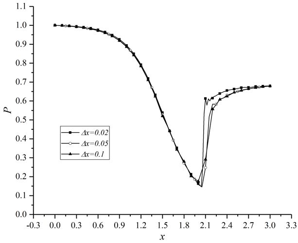
ICMMAP 2021 IOP Publishing
Journal of Physics: Conference Series 2012 (2021) 012096 doi:10.1088/1742-6596/2012/1/012096

 (c) Density (d) Temperature

 (e) Velocity
 Figure 5. Comparison of different grids.
 In the following, the study focuses on the variations of Mach number, pressure, density,
temperature and velocity for different grids. The control condition is to maintain an outlet pressure of
0.68 and change the grid length to be 0.02, 0.05 and 0.1.
 In Figure 5(a), when the grid is divided into smaller and finer, such as taking for 0.02, the
maximum Mach number achievable in the nozzle is about 1.91. By comparison, it is found that as Δx
gradually decreases, the maximum Mach number in the nozzle increases. As the mesh is divided finer
and finer, the maximum Mach number will gradually converge to a definite value rather than an
infinite growth. It also finds that the position where the shock wave appears is almost unaffected, all
around the horizontal coordinate of 2.1. In Figure 5(e), the variation rule of the velocity is basically the
same as the Mach number.
 Moreover, the change in pressure, density and temperature are also basically similar. Therefore, the
pressure distribution is chosen as an example to be analysed. As decreases from 0.1 to 0.02, the
minimum value of pressure generated within the nozzle becomes smaller. When Δx is divided into
finer and finer, the minimum value of pressure does not keep decreasing but converges to an exact
value of 0.14. The curve of temperature is a bit special, when the mesh is relatively small such as Δx =
0.02, the change of temperature starts to fluctuate at the position where the horizontal coordinate is
greater than 2.1.
 The above results show that the smaller the Δx is, the more accurate the variable distributions are.
In general, increasing the number of grids can improve the measurement accuracy but also increase the
complexity of the calculation. However, as Δx decreases to 0.05, the accuracy of the curve hardly
changes anymore and it is almost the same as when Δx = 0.02. So Δx = 0.05 is chosen in the present
work.

 8
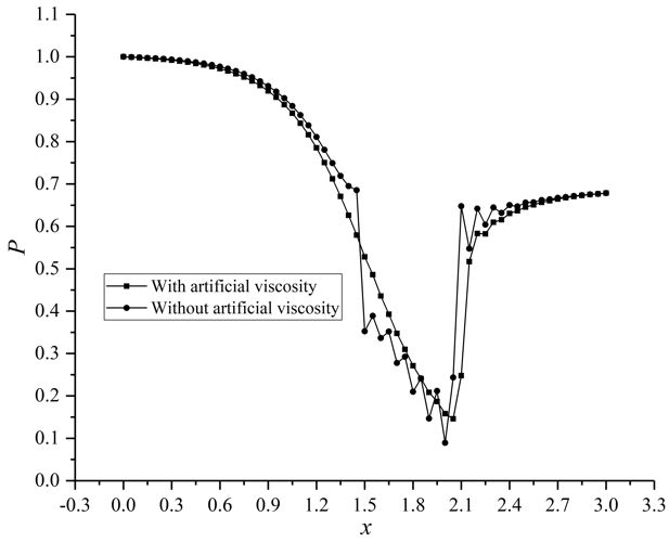
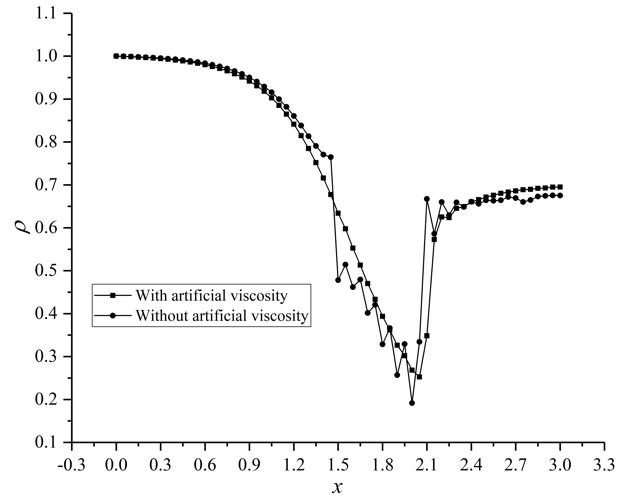
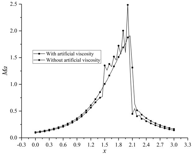
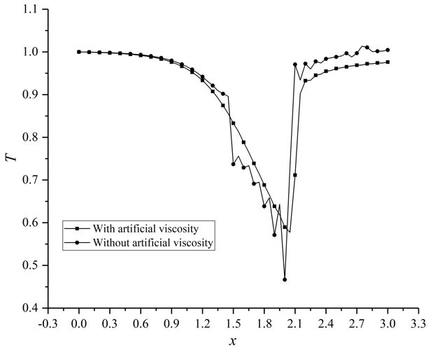
ICMMAP 2021 IOP Publishing
Journal of Physics: Conference Series 2012 (2021) 012096 doi:10.1088/1742-6596/2012/1/012096

3.3. Comparison of numerical results with and without artificial viscosity term

 (a) Mach number (b) Pressure

 (c) Density (d) Temperature

 (e) Velocity
 Figure 6. Comparison of numerical results with and without artificial viscosity term.

 Figure 6 shows the comparison of the Mach number, pressure, density, temperature and velocity
profiles with and without the artificial viscosity. It is shown that if the artificial viscosity term is added,
the results of the numerical calculations will become more stable, more convergent. Without adding
the artificial viscosity term, The numerical results are very oscillating and inaccurate, especially in the

 9
ICMMAP 2021 IOP Publishing
Journal of Physics: Conference Series 2012 (2021) 012096 doi:10.1088/1742-6596/2012/1/012096

region of supersonic speed before the shock wave. So, adding the artificial viscosity term is chosen in
the present work.

3.4. Comparison at different outlet pressures
In order to compare the influences of different outlet pressures on the flow state inside the nozzle,
simulations are carried out separately for different outlet pressure pe.

 (a) Mach number (b) Pressure

 (c) Density (d) Temperature

 (e) Velocity
 Figure 7. Comparison at different outlet pressures.

 10
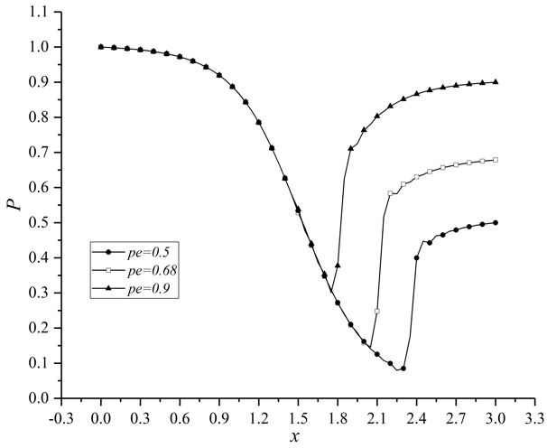
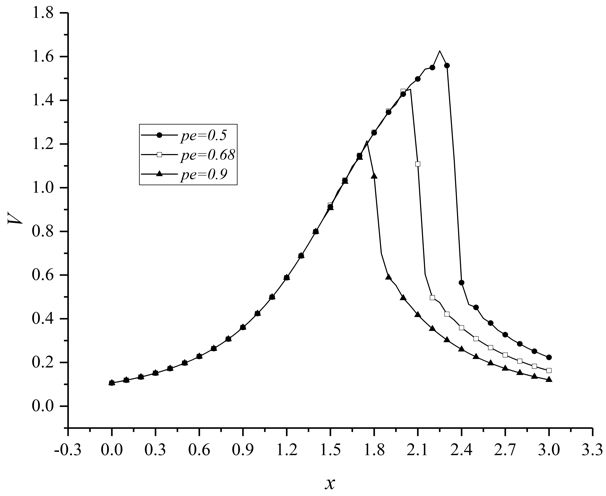
ICMMAP 2021 IOP Publishing
Journal of Physics: Conference Series 2012 (2021) 012096 doi:10.1088/1742-6596/2012/1/012096

 Figure 7(a) shows the Mach number distributions of the nozzle under different outlet pressures.
The overall trend is to first increase and then reach a maximum point, followed by a sharp drop in
Mach number over a little distance, and finally, the curve flattens out. The cusp of the curve represents
the shock wave, which appears behind the throat. As pe = 0.68, the shock wave appears at the position
where the dimensionless distance equals nearly 2.1. While pe is equaled to 0.5, the shock wave
appears near the dimensionless distance of 1.8. As pe equals 0.9, the position of the shock wave
appears at about 2.4. In general, as the pe increases, the location where the shock wave appears also
moves to the right. The Mach number becomes larger as the outlet pressure increases at the same
location after the appearance of the shock wave.
 The pressure distributions under different outlet pressures are shown in Figure 7(b). As can be seen,
the pressure changes very little near the initial position, and then the pressure starts to gradually
decrease as x reach 0.6. After reaching the lowest point, it turns sharply up and finally levelled off near
the nozzle outlet. After comparison, it is found that the pressure is the same at the position before the
appearance of the shock wave, regardless of the outlet pressure. After the appearance of the shock
wave, the pressure gradually becomes larger at the same position with the increase of pe. At a pe of
0.5, the dimensionless value of pressure at the point of 2.5 is only 0.44, while this value becomes 0.87
when the pe increases to 0.9.
 In addition, the distribution of density and temperature and the distribution of pressure can be
found to be consistent. The distributions of velocity and Mach number are consistent. The above
analysis provides a clear understanding of the influences of outlet pressure on the flow state in the
nozzle.

4. Conclusion
The McCormack scheme is used to discretize the conservation form of the governing equations of the
flow in the nozzle. The problem can be reduced to a quasi-one-dimensional flow problem. The results
indicate that the numerical solution is in good agreement with the theoretical solution. The artificial
viscosity term can make the solution smoother and more accurate. More, larger pressure will cause
less peak and trough values of Mach number, the pressure within the nozzle, density, temperature and
velocity with the earlier appearance of these extremum values for the subsonic-supersonic isentropic
nozzle. Besides, the shock wave was accurately captured and located behind the throat. Finally, the
flow state inside the nozzle can be understood in detail through the research results of this paper. Since
there are many factors that can influence the basic properties of the fluid within the nozzle and the
location of the shock wave, the further and comprehensive study should be taken on integrating all
factors that can impact the results, different methods likewise, in order to obtain a solution which can
be implemented in real situations.

References
[1] Deshpande N.D., Vidwans S.S., Mahale P.R., Joshi R.S., Jagtap K.R. (2014) Theoretical and
 CFD Analysis of De-Laval Nozzle International. Journal of Mechanical And Production
 Engineering, 2:2320–2092.
[2] Clarke, C., Carswell, B. (2007) Principles of astrophysical fluid dynamics. Cambridge
 University Press, Cambridge.
[3] Patel M.S., Mane S.D., Raman M. (2016) Concepts and CFD Analysis of De-Laval Nozzle.
 International Journal of Mechanical Engineering and Technology, 7:221–240.
[4] Canosa, A., Ocaña, A., Antiñolo, M., Ballesteros, B., Jiménez, E., Albaladejo, J. (2016) Design
 and testing of temperature tunable de Laval nozzles for applications in gas-phase reaction
 kinetics. Experiments in Fluids, 57:152.
[5] Li, J., Xin, Z., Yin, H. (2012) Transonic Shocks for the Full Compressible Euler System in a
 General Two-Dimensional De Laval Nozzle. Archive for Rational Mechanics and Analysis,
 207: 533-581.

 11
ICMMAP 2021 IOP Publishing
Journal of Physics: Conference Series 2012 (2021) 012096 doi:10.1088/1742-6596/2012/1/012096

[6] Wang, C., Xin, Z. (2019) Smooth Transonic Flows of Meyer Type in De Laval
 Nozzles. Archive for Rational Mechanics and Analysis, 232:1597-1647.
[7] Matz, M., Aumiller, M. (2014) Practical Comparison of Cylindrical Nozzle and De Laval
 Nozzle for Wire Arc Spraying. Journal of Thermal Spray Technology. 23:1470-1477.
[8] Cheng, J., Du, L., Xiang, W. (2018) Incompressible Jet Flows in a de Laval Nozzle with
 Smooth Detachment. Archive for Rational Mechanics and Analysis, 232:1031-1072.
[9] Dykas, S., Majkut, M., Smołka, K., Strozik, M. (2018) An attempt to make a reliable
 assessment of the wet steam flow field in the de Laval nozzle. Heat and Mass Transfer.
 54:2675-2681.
[10] Xu, L., Zhou, X., Li, J., Hu, Y., Qi, H., Wen, W., Du, K., Ma, Y., Yu, Y. (2020) Numerical
 Simulations of Molten Breakup Behaviors of a de Laval-Type Nozzle, and the Effects of
 Atomization Parameters on Particle Size Distribution. Processes. 8:1027.
[11] Hatta, N., Fujimoto, H., Ishii, R., Umeda, Y., Kokado, J. (1989) Numerical study on supersonic
 flows of gas-liquid particle mixtures in a De Laval nozzle. ISIJ International, 29:911-918.
[12] John D. Anderson, Jr.. (1995), Computational Fluid Dynamics: The Basics with applications,
 Singapore: McGraw-Hill Book Co..

 12
You can also read