Verification of Spread Spectrum Correlator - IAENG
←
→
Page content transcription
If your browser does not render page correctly, please read the page content below
Proceedings of the World Congress on Engineering 2021
WCE 2021, July 7-9, 2021, London, U.K.
Verification of Spread Spectrum Correlator
Akhhiila Gurram, Navika Iyer, and Lili He, Member, IAENG
Abstract- Since the early 1940s, military communication The design verification process is not simply linear, but
systems, regular networking, and wireless communication it is a continuous process to test until it meets the
systems use spreading techniques. One such technology is requirements.
Spread Spectrum, where the waveform is modulated by
Universal Verification Methodology is a standard
spreading the bandwidth using a pseudorandom noise, thereby
encrypting the signal. The project verifies a spread spectrum verification methodology consisting of class libraries
correlator and checks for its verification properties. It aims to required to build reusable test benches for the System
check the correlators through 14 different designs under tests Verilog-based environment. It works on a message-based
(DUTs) while correlating to the gold code (PRN), frequency, programming model where the UVM components
and phase. It further aims to check the correlation properties communicate with messages.
with frequency errors and phase errors. This project will allow
upgrading systems with spread spectrum techniques to send II. METHODOLOGY
and receive information with finer encryption. The project
aims to provide full functional verification of the design and UVM is a standard methodology used in verification to
check if the design meets the specification requirements. The test functionality, timing, and performance. Types of
results of the project show plot of correlation characteristics verification: Simulation, assertions, formal, semi-formal,
with frequency and phase errors. and HW/SW. Verification of spread spectrum correlator
tests functionality by building class libraries to test the
Index Terms— Gold Code, Pseudorandom Noise, Spread System Verilog-based environment. It uses messages, data
Spectrum Technique, Universal Verification Methodology collection, and class objects to communicate with multiple
UVM components through TLM interfaces, ports, exports,
I. INTRODUCTION and imps. UVM classes have UVM transactions,
The Spread Spectrum technique is used in components, and objects where each of them performs
communication systems by increasing the transmission different tasks. The verification runs in 9 different phases.
bandwidth to secure and reliable communication [1]. A. UVM Components
Narrowband signals transmit information; however, they are
intercepted easily. Any signal in the same band could easily
jam the narrowband signals leading to loss or delicate
information corruption. If there is a low S/N ratio due to
interference, communication performance (C) increases the
bandwidth by injecting a higher frequency signal.
The Shannon and Hartley channel-capacity theorem
explains Spread Spectrum using equation [2]:
(1)
Where C stands for Channel Capacity (in bits/second), B
stands for required channel Bandwidth (in Hz), and S/N is
the Signal to Noise power Ratio. To apply the spread Fig. 1. Block diagram of Spread Spectrum Communication
spectrum technique to any channel; before the receiver
antenna, insert the spread spectrum code; this is known as Major UVM components are sequencer, driver, monitor,
the spreading operation leading to the diffusion of scoreboards, agent, environment, test, and top module, and
information to a larger bandwidth. The Spread Spectrum each of these components extends to a base class. UVM
technique applies on top of another modulation technique Sequencer sends the sequence items generated by the
such as BPSK[3]. Verification is the process of determining sequence to and from the driver with a built-in export called
the correctness of a design. It checks if the design developed seq_item_export. UVM driver collects the sequence items
is according to the specifications before process installation sent by the sequencer and pushes them into the design under
and optimization. test. It uses a configuration database to access the virtual
interface, which connects to the Design under test. During
Akhhiila Gurram is a student at San Jose State University, San Jose, CA. the driver's run phase, the sequence item fields map to the
USA. phone: (925)-520-5274. email: akhhiila.gurram@gmail.com
Navika Iyer is a student at San Jose State University, San Jose, CA, USA.
virtual interface handle. Therefore, the sequence items
phone: (408)-797-4212, email: navika.iyer20@gmail.com convert to pin wiggles and apply to DUT. It continuously
drives the interface signals to the DUT throughout the
simulation time.
ISBN: 978-988-14049-2-3 WCE 2021
ISSN: 2078-0958 (Print); ISSN: 2078-0966 (Online)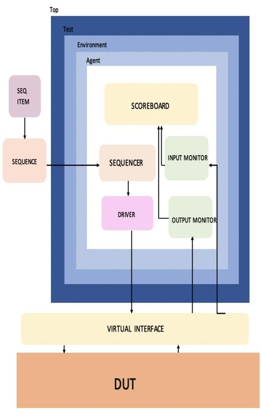
Proceedings of the World Congress on Engineering 2021
WCE 2021, July 7-9, 2021, London, U.K.
UVM Monitor collects the signal level activity from the message and keep in mind that the message sent will
design through the virtual interface, converts it to encounter various noise types. [7]
transaction items, and sends it to the other UVM
B. Modulator
components. It uses a configuration database to access the
virtual interface connected to the Design under test. The The modulator is responsible for converting the message
data transfers through TLM analysis ports. UVM bits into signals to send through a channel. There are
Scoreboard component checks the functionality of the DUT, different types of modulation techniques used in the
whether the design is behaving correctly and according to industry, such as Phase Shift Keying (PSK), Frequency Shift
the requirements or not. It receives the data from the Keying (FSK), and Amplitude Shift Keying (ASK), among
monitor through analysis ports and stores the data in others.[7]
analysis FIFOs. C. Channel
UVM Agent is an abstract container class used to
The channel is the physical medium of message
emulate and verify the Design under Test. It encapsulates a
transportation. A channel also includes attenuation, noise,
driver, sequencer, and monitor. All the components are
and interference to the message signal.
connected using TLM interfaces. The connect phase is the
most critical phase as it connects all the agent's child D. De-modulator
classes. The de-modulator is responsible for converting the
UVM Environment is a container class for multiple signals received through the channel back to bits. The
agents and other components like scoreboards, top-level demodulation technique used is the same as the modulation
monitors. technique used to transmit the signal at the sender side.
UVM test contains the environment which, acts as a
container class. The top module contains all the components E. Decoder
like the test, packages, interface, and DUT. Import UVM A decoder is finally responsible for converting the bits
packages using "import uvm_pkg::*:" and run_test is into understandable and readable messages as sent by the
declared invoking to build the UVM test component sender.
responsible for building the UVM hierarchy. F. Spreading and de-spreading code
B. UVM Phases This additional code is added to the signal while
There are nine phases in UVM. Build phase, connect modulating and demodulating respectively to spread the
phase, end of elaboration phase, the start of simulation signal's bandwidth and make it immune to interceptions.[8]
phase, run phase, extract phase, check phase, report phase,
and final phase. These phases are essential to build, connect IV. THE DESIGN UNDER TEST
and run the UVM components to act in a synchronizing Of the six inputs, Din is the input data signal, while the
mechanism. The build phase is top-down, while the rest of address register is to determine the use of Din. A strobe
them are bottom-up. The extract phase, check phase, report signal is a one-bit signal used to determine when to write or
phase, and final phase are together called clean-up phases. check the address register. The fourth input signal is Samp
The run phase is the only phase with a method-type task and it is used to get the sample value.
while the rest of them use functions [4-5]. The last input signal is push_samp which determines
C. UVM Objects when the Sample value is available.
UVM object, unlike the UVM component, is not There are four outputs; Dout is the same value as Din.
required to stay alive during the entire simulation. Sequence The second output is the correlator which is the actual
and Sequence items are the only two objects, and they output, and the third output is just a one-bit flag which is the
extend to a base class. UVM Sequence and Sequence item push_correlator which signifies that the correlator output is
classes are built with macros, registered with a factory, and ready.
provided stimulus, triggered during UVM phases. The Table I. Design Specifications
classes use item methods like create (), copy (), clone (), Name Size Direction
print ().
Din 32 bits Input
III. SPREAD SPECTRUM TECHNIQUE Addr 4 bits Input
Spread Spectrum's idea is to increase the bandwidth of Strobe 1 bit Input
the signal transmitted but, at the same time, maintaining the Sync 1 bit Input
power level, and this leads to indistinguishable peaks in a Samp 12 bits Input
spectrum, which looks like noise. Since the information
cannot be differentiated from noise unless the receiver has Push_samp 1 bit Input
proper decoding techniques, it is tough to intercept or jam Dout 32 bits Output
these signals. The spread spectrum has emerged as one of Corr 32 bits Output
the most secure ways of transmitting the information.[6] Push_corr 1 bit Output
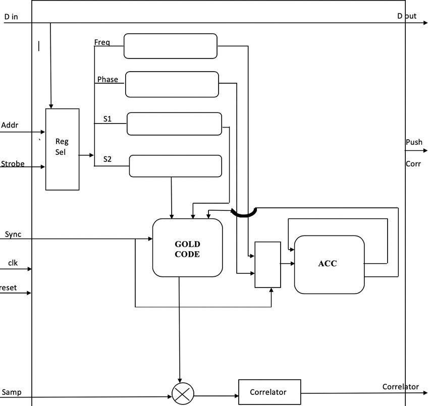
The 6 components of the block diagram are explained as
follows
The first module is called the Register Select Module. As
A. Encoder the name suggests, the responsibility of this module is to
The encoder is responsible for converting messages into select the register for input data. The first signal checked is
bits (or signals). It removes redundancy to compress the
ISBN: 978-988-14049-2-3 WCE 2021
ISSN: 2078-0958 (Print); ISSN: 2078-0966 (Online)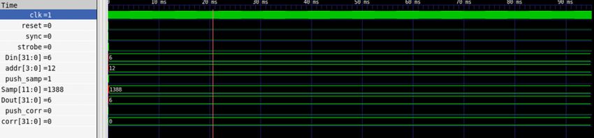
Proceedings of the World Congress on Engineering 2021
WCE 2021, July 7-9, 2021, London, U.K.

  push_Samp. If push_Samp is high, the sample input is then            V. UVM TESTBENCH
  read.
                                                                         A. Interface
      The address signal has only four values considered in the
  design. If the address is 0, 4, 8, 12, that means the input data         The interface has input and output signals with a
  is equal to frequency, phase, S1, S2 register, respectively.         clocking block, and the modport is a named port where the
  S1 and S2 registers are responsible for selecting tapping bits       direction of the signals is specified. The interface acts as a
  for polynomials in the Gold Code. If the sync is high in the         medium between the design and the uvm testbench to
  accumulator module, it sets the accumulator equal to phase.          exchange the signlas.
      If the push_samp is high and sync is 0, then the                   B. Sequence Item
  accumulator keeps adding frequency to itself. Once the                   The class is registered with the factory “uvm_ object_
  accumulator value crosses 100 Million, 100,000,000                   utils” and constructed using a class constructor. The items
  subtracted from it, and raise a flag to indicate the Gold Code       are created in the body using type_id:: create. The body of
  to advance to the next chip.                                         the sequence calls for multiple tasks. These tasks include
      Every time the accumulator crosses 100 million and               directed test case by specifying the Din value as 100
  raises the flag, there is a counter to increment in the gold         Million, push samp = 1, Samp = 1388 and address= 4'h0,
  code module. The Gold Code [9-10] module consists of two             4'h4, 4'h8, 4'hC, and strobe = 1.
  polynomials. Both of them are set to 10'b1111111111 when
  the sync signal is high. Four temporary registers aid in the           C. Sequencer
  calculation of the gold code output. The 10th bit is taken               The class registers with the factory UVM “component
  from the first polynomial and stored in the first register.          utils.”
  Then 2 bits are taken from the second polynomial, XORed
  together, and stored in the second register. The output of the         D. Driver
  gold code is the modulo two addition of register one and                 The driver class's build phase has the configuration
  register 2, and the gold code output becomes 0 [11]. Once            database to access the design through a virtual interface.
  the accumulator raises its flag, move on to the next chip.           Failing to connect will show a fatal error. The connect phase
  The two taps on polynomial 1 are modulo two added                    connects the ports. The interface signals take sequence items
  together, and the polynomial is left-shifted by one and then         into at the positive edge of the clock. The sync signal is set
  repeat the same process.                                             high for every alternative clock cycle, and the driver uses its
      Once the counter reaches 1023, the push_corr flag goes           inbuilt seq_item_port to get signals from the sequencer and
  high. Gold code output determines whether the sample value           item.done method use the items[11].
  is added or subtracted to the correlator value and gives the         E. Input and Output Monitor
  final output. Din directly goes into Dout.
                                                                           The monitor's build phase has the configuration

                                                   Fig. 2 Block Diagram of Spread Spectrum

ISBN: 978-988-14049-2-3                                                                                                      WCE 2021
ISSN: 2078-0958 (Print); ISSN: 2078-0966 (Online)
Proceedings of the World Congress on Engineering 2021
WCE 2021, July 7-9, 2021, London, U.K.
database, so the monitor accesses the design through a The four scoreboards send and receive messages to
virtual interface. imitate the correct function of the Spread Spectrum
. Correlator. The reg select scoreboard performs a register
select operation. The accumulator scoreboard performs the
frequency addition and raises a flag. The gold code
scoreboard checks the tapping polynomials in register S1
and S2 and performs the operations. The correlator
scoreboard receives the output, which checks for the
accumulator flag and increments the correlator counter.
Once the counter reaches 1023, check the gold code output.
According to the gold code output, the correlator adds or
subtracts the previous value to the sample and gives it.
The 5th scoreboard, which is the checker scoreboard,
compares the output achieved using the reference model to
the actual output from the DUT. If it matches, the design
passes the test; otherwise, it fails the test.
G. Agent
The agent connects all the child classes like the
scoreboards, monitors, driver, and sequencers after the build
phase achieves proper hierarchy.
H. Environment
The environment class connects to the agent and builds a
hierarchy. The agent class item is created in the build phase
using type_id::create. The connect phase connects its child
classes, and it is displayed.
I. Test
Fig. 3. UVM Testbench Block Diagram The test class is the last in the hierarchy, which connects
Analysis ports use messages for communication between the environment and the sequence. The items for the
components. The task enabling the run phase has the input environment and sequence class are created in the build
interface signals that push into sequence items at the phase using type_id::create, and the run phase has phase
clock's positive edge. objections to signify the start and end of the test.
F. Scoreboard
There are five different scoreboards used in this project.
Each checks a separate module of the test and sends
information to each other through messages.
Fig.4. Simulation results of passed DUTs
ISBN: 978-988-14049-2-3 WCE 2021
ISSN: 2078-0958 (Print); ISSN: 2078-0966 (Online)Proceedings of the World Congress on Engineering 2021
WCE 2021, July 7-9, 2021, London, U.K.
Fig. 5. Waveform of DUTS that failed the test
Fig. 6. Zoomed waveform of the DUTs
Fig. 7. Waveform of the DUTs that passed the test
J. Top Module
instantiate the DUT, and set the configuration database. For
The top module encapsulates the entire uvm a better representation, create waveform files using dump
environment. We include all uvm component and object files [12]. The virtual interface is present in configuration
files at the top to be built and used. After initializing the database allows us to access from uvm components like
clock and reset, provide the virtual interface handle, driver and monitor.
ISBN: 978-988-14049-2-3 WCE 2021
ISSN: 2078-0958 (Print); ISSN: 2078-0966 (Online)Proceedings of the World Congress on Engineering 2021
WCE 2021, July 7-9, 2021, London, U.K.
VI. RESULTS [3] S. Kulkarni, P. Mazumder and G. Haddad, "A high-speed 32-bit
parallel correlator for spread spectrum communication", IEEE,
14 DUTs were tested 7 DUTs failed the test and 8 DUTs Bangalore, India, 1996.
Passed. This section shows screen captures of the simulation [4] A. Goiser and M. Sust, "Spread Spectrum communication using
CMOS digital correlator", IEEE, Lisbon, Portugal, 1989.
results as well as the waveforms achieved by DUTs. [5] A. Hendrickson, "Verification of PN Synchronization in a Direct-
Fig. 4 shows the simulation results of the DUTs that Sequence Spread Spectrum Digital Communication System",
passed the test. The expected and received values match; US6002709, 1999
Fig. 8. Simulation results of DUTs that failed the test
therefore, the DUTs correlated correctly.Fig. 5 shows the [6] J. Yun, "Adaptive acquisition method and apparatus for CDMA and
simulation results of DUTs that failed. Fig. 6 shows the spread spectrum systems compensating for frequency offset and
zoomed-in waveform of the DUT, which passed the
noise", KR100473679B1, 2005
testbench. When the push corr is high, push the value of the [7] V. Nath and A. Kumar, "A Comparative Study of Spread Spectrum
corr. Fig. 7 shows the waveform of the DUT till the end of Technique based on Various Pseudorandom Codes", Global Journal
simulations which passed the testbench. When the push corr of research in engineering, vol. 12, no. 6, 2012.
Available:https://pdfs.semanticscholar.
is high, push the value of the corr, as seen in fig. 7.
org/b821/b35033237efd3c31bb016e93bb9d87e49e46.pdf. [Accessed
As shown in the figure, the expected and received 16 September 2019].
outputs from the correlator do not match; therefore, the [8] "Exploring communications technology", OpenLearn, 2020. [Online].
DUTs failed the test. Fig. 8 shows the waveform of the Available:https://www.open.edu/openlearn/science-maths-
technology/exploring-communicationstechnology/content-section-1.4.
result which failed. The other DUTs never gave out any [Accessed: 03- Feb- 2020].
outputs because the push corr never went high, implying the [9] "Understanding Spread Spectrum for Communications - National
corr value was never given out. Instruments", Ni.com, 2020. [Online]. Available:
https://www.ni.com/en-us/innovations/whitepapers/06/
understanding-spread-spectrum-for-communications.html. [Accessed:
VII. CONCLUSION 07- Mar- 2020].
The project's objective was to provide functional [10] "The GPS PRN (Gold Codes)", Natronics.github.io, 2020. [Online].
Available:https: //natronics.github.io/blag/ 2014/gps-prn/. [Accessed:
verification for the spread spectrum correlator and plot its 13- Feb- 2020].
correlation characteristics. It has successfully achieved [11] Huang, Kai & Zhu, Peng & Yan, Rongjie & Yan, Xiaolang. (2015).
functional verification by building an environment “Functional Testbench Qualification by Mutation Analysis”. VLSI
consisting of agents, drivers, monitors, and Scoreboards of Design. 2015. 10.1155/2015/256474.
[12] Saponara, Sergio & Vitullo, Francesco & Petri, Esa & Fanucci, Luca
the main blocks like Accumulator, Correlator, and the Direct & Coppola, Marcello & Locatelli, Riccardo. (2011). “Coverage-
Digital Synthesizer. The correlator output was verified and Driven Verification of HDL IP Cores”. 10.1007/978-94-007-0638-
shown in the results. 5_8.
REFERENCES
[1] "An Introduction to Spread-Spectrum Communications - Maxim",
Maximintegrated.com, 2003. [Online]. Available:
https://www.maximintegrated.com/en/design/technicaldocuments/tuto
rials/1/1890.html. [Accessed: 02- Oct- 2019].
[2] V. Eerola and T. Ritoniemi, "Signal Acquisition System for Spread
Spectrum Receiver", US6909739B1, 2005.
ISBN: 978-988-14049-2-3 WCE 2021
ISSN: 2078-0958 (Print); ISSN: 2078-0966 (Online)You can also read


