The Interior Side of Revit: Documenting Interior Design Projects with Autodesk Revit
←
→
Page content transcription
If your browser does not render page correctly, please read the page content below
The Interior Side of Revit: Documenting Interior
Design Projects with Autodesk® Revit®

Damian Serrano, Assoc. AIA, Project/BIM Coordinator -- RLF Inc.
Scott D. Brown, AIA, Director of Building Information Modeling – HHCP

AB5151 Revit is a great tool for architects, structural engineers, and MEP engineers—but what about
interior designers? This class will answer some of the many questions faced by interior designers who are
developing projects in Revit. What is the best way to represent finishes in schedules and elevations? How
do I coordinate room finish information if the rooms are in a linked model? How do I coordinate
comprehensive interior design (CID) packages to schedule equipment and furniture? What about
signage? Join us and learn innovative strategies for integrating interior design into your project models.

Learning Objectives
 At the end of this class, you will be able to:
•   Set up interior design models in different scenarios of multi-discipline collaboration
•   Use key schedules to assign rooms comprehensive finish information such as manufacturer, color,
    model, etc. and set up finish schedules
•   Create floor patterns, wall finish floor plans and elevations leveraging model and schedule information
•   Define strategies for modeling and coordination of Equipment, Furniture and Signage packages

About the Speakers:
Damian is a Project/BIM Coordinator with RLF, a nationally recognized A/E firm specializing in healthcare
and government projects. With 19 years of experience in the AEC arena, Damian has been a key player
in RLF's migration from CAD to BIM. Damian is a Revit Architecture Certified Professional and also an
Adjunct Instructor at Seminole State College of Florida and Valencia Community College. He
implemented the first BIM/Revit class at college level in the Central Florida area. Damian has a degree in
Building Design and Construction and an Architecture degree from University of Buenos Aires, Argentina.
damian_serrano@rlfae.com

Scott is a licensed Architect with 16 years of project experience. For the past 10 years, Scott has been
training architects, designers and students on Revit. He is a founder and former president of the Central
Florida Revit user group. Scott earned his Bachelor of Environmental Design from the University of
Colorado, Boulder. Scott is currently a Project Coordinator and the Director of Building Information
Modeling for HHCP Architects in Maitland, Florida.
sdbrownaia@gmail.com or sbrown@hhcp.com

*We would like to thank Miriam Ganesh, IIDA, LEED AP, who also contributed to this class.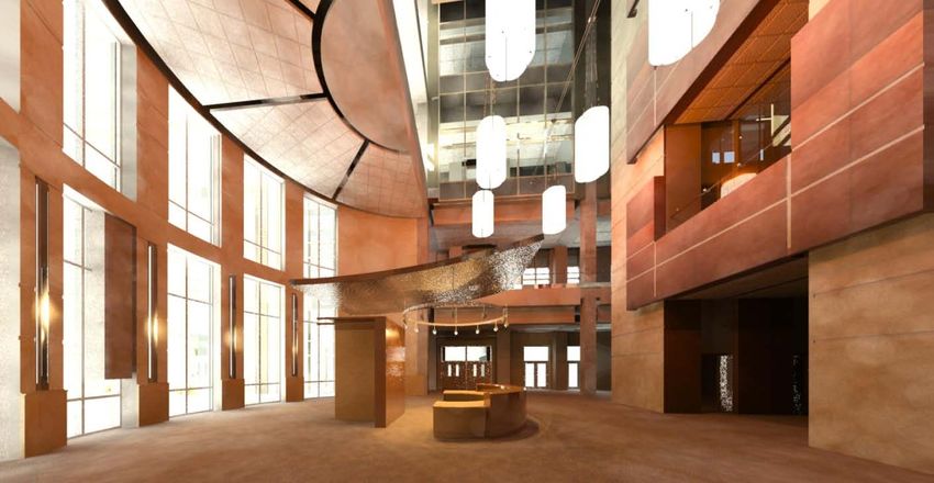
The Interior Side of Revit

Class Outline

•     Introduction
•     Model Setup, Architecture, Interior Design, Equipment
•     Room Finish Schedules / Finish Key Schedules
•     Floor Finish Plans
•     Wall Finish Plans
•     Interior Elevations
•     Millwork Elevations and Details
•     Equipment 2D/3D
•     Furniture & Artwork 2D/3D
•     Signage
•     Materials
•     Rendering Tips
•     Conclusion
•     Q&A

                                                                                      2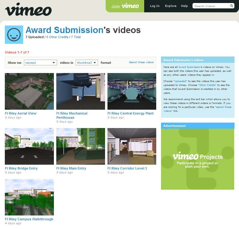
The Interior Side of Revit

Introduction
It is typically said that Revit is not a user friendly tool for interior designers in the way that they document
their work. While it may be true that Revit still needs to address some of the requirements for interior
designers, our ID departments have embraced this technology and are leveraging its capabilities to
produce great results (Fig. 1).

Fig. 1: RLF’s Interior Design department has embraced Revit and is leveraging its capabilities to produce
great results. Project: Veteran Affairs Medical Center, Orlando, FL

Typically, interior design tasks include two main components: Structural Interior Design (SID) and
Comprehensive Interior Design (CID). The SID portion includes finish selection and documentation, floor
finish plans, wall finish plans, interior elevations, millwork elevations, millwork details and exterior and
interior signage. The CID encompasses selection and placement of furniture and artwork. Since many of
our projects are healthcare-related, this package also includes coordination with medical equipment
throughout the facility.

                                                                                                                   3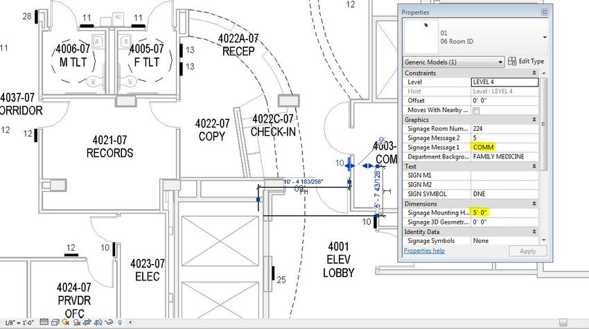
The Interior Side of Revit

The Interior Model Setup

Correctly setting up the models is one of the keys to develop projects in Revit efficiently. Wrong decisions
made at the beginning of a project can have impact throughout the design and documentation phases,
making coordination more complicated and wasting hours of labor.
When we first started using Revit, architecture and interior departments would share a single Revit model.
This worked very well for small projects - which as a rule of thumb we consider to be less than 10,000
square feet. However for larger projects, working in a single model created significant problems as files
became too large often burdening our network and crashing our computers. As a result we decided to
create separate models. The interior model, which we refer to as the ID/EQ model, not only houses all
interior design aspects, but also serves as the model used by our medical equipment planning team.
Architecture and engineering models are linked into the ID/EQ model, which helps to manage the data
with better coordination and efficiency.

One of the main differences of working in a separate interior design model is that instead of including
Revit “rooms” (seen in blue below) as in the architecture model, we use Revit “spaces” (seen in green
below). Revit “spaces” were originally developed for Revit MEP and act similarly as rooms in their
behavior and properties. Once placed in the model, a space can detect the room located in the same
physical location in the linked model and read its name and number. The room name and number can
then be copied to the space, if desired. Spaces can be assigned parameters for finishes and can be
reported in furniture and equipment schedules. These characteristics and others make “spaces” perfectly
adequate to use in interior models. Also, it is important to mention that working with spaces does not
require a Revit MEP license, although their creation is simplified if you have one.

Fig. 2-3: The architecture model includes the rooms (shown in blue) and the interior-equipment model has
spaces (shown in green) that are “connected” to the rooms in the linked model.

                                                                                                           4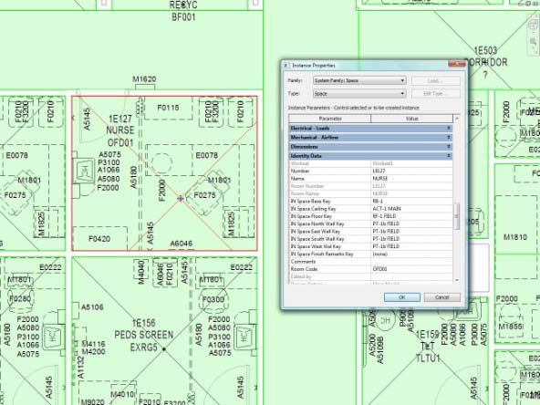
The Interior Side of Revit

The SID: Finish Documentation

There are two main ways to document finishes in a BIM project:

    1. Room Schedule based: the rooms contain finish information in multiple parameters and they are
       shown in schedule format.
    2. Model based: the finishes are modeled to the maximum extent possible and are identified in floor
       plans and interior elevations.

Unfortunately these two methods do not talk to each other.
That means that room parameters cannot read material
information from the adjacent walls, floor and ceilings and
report it. As a result you have to pick using one or the other, or,
as we typically do, using both and coordinating manually.

Schedule based finishes

Room finishes can be documented through parameters
assigned to Revit rooms or spaces. These can include surfaces
such as floor, base, wall (north, south, east and west), and
ceiling. When parameters are assigned a value, they populate
the room finish schedule, which technically is a space schedule
in Revit. The values assigned come from key schedules which
contain all the information about the finish. For example, when
a finish is assigned a value such as PT-1, this is a key that
includes all of the information about the finish such as
manufacturer, color, style, size, etc. (Fig. 4) This information
allows us to create simultaneous parametric finish identification
schedules (Fig. 5) which can also be used for quality control
purposes: in order for a finish to list in this schedule, it has to
have been used in a room or space.

Fig. 4: Finish information is included as parameters of rooms or
spaces. Every finish is a key parameter that drives additional
information, such as material, manufacturer, color, pattern, etc.

Fig. 5: Parametric Finish Identification Schedules are used for the CDs, but also as a QA/QC tool.

                                                                                                          5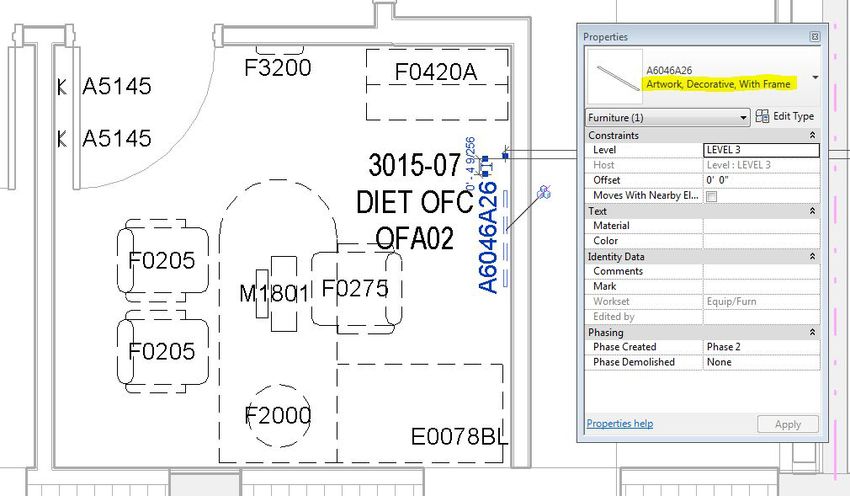
The Interior Side of Revit

Model based finishes: Floor Finish Plans

At RLF it is standard procedure to show a pattern in any room with more than one finish. If a room has
only one finish and is left without a pattern, it is because it is covered by the finish schedule. In order to
create patterns, we model floor finishes in 3D using the floor tool in Revit and give each floor a true
thickness that represents the material being used. This floor is also assigned a hatch pattern so it can be
easily distinguished when printed (Fig. 6). For any other discipline linking to our model, it is very easy to
hide the patterns by using Visibility/Graphics Overrides to turn off the floors from the ID/EQ model.

Along with the floor patterns displayed in our floor finish plans, we list pattern direction for flooring that
has grain, dimensioning and other pertinent information to assist in installation.

Fig. 6: Floor Patterns are represented with 3D objects in the Interior Design model.

                                                                                                                 6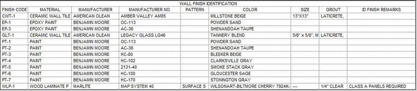
The Interior Side of Revit

Model based finishes: Wall Finish Plans

Our interior designers use wall finish brackets to identify wall finishes in plans for rooms with multiple
room finishes (Fig. 7). These brackets were created in-house as a family that can be stretched, flipped
and rotated. We also note interior finish elevations in plans as well as dimensions for any wall paneling.
The material is then noted with a wall tag.

Fig.7: Wall finishes are represented with stretchable brackets. The material note is a wall tag.

Fig. 8: The stretchable bracket is a detail family used to show the extents of a finish in Floor Plan.

                                                                                                             7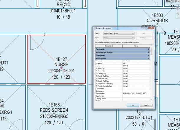
The Interior Side of Revit

Model based finishes: Interior Elevations

Revit is a great tool for interior elevations since they are very realistic depictions of what a space will look
like.Interior elevations, which show material and color transitions on a wall with multiple finishes. Wall
finishes are modeled with the wall tool if they have a significant thickness, i.e. tile, stone, wall panel
systems, etc. They are assigned materials that can be tagged in the elevations (Fig. 9).

Fig. 9: Wall Finishes are modeled and assigned materials that can be tagged.

                                                                                                               8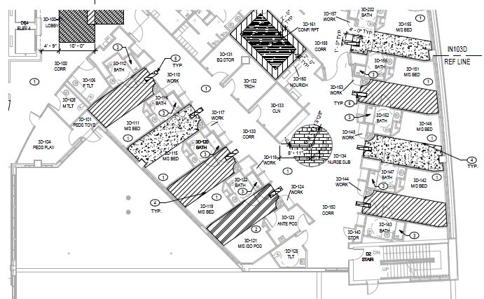
The Interior Side of Revit

Millwork Elevations

Millwork elevations show the front, side and back appearance of any piece of custom millwork. Millwork is
represented with 3D families that are visible in an elevation even if the vantage point is changed; these
families are specific to each project and they are created with parametric dimensions based on design
requirements (Fig. 10-11). We apply finishes and materials to the geometry parameters so we can
schedule them in millwork schedules.

Fig. 10-11: Custom millwork is developed in 3D to simplify the creation of interior elevations.

Millwork Details

Millwork details in Revit are drawn using drafting views with detail components; these detail component
families have been assigned a keynote value that allow us to tag them, creating a reference to the
specification sections for the contractor. By creating these drafting views, we are then able to create
section markers in the elevations as shown in Fig. 10-11 and link them to the millwork sections shown
below (Fig. 12) with the option “reference other view”. Anyone that is reviewing the elevation can double
click on the section cut and be directed to the detail.

Fig. 12: Millworks sections are represented with 2D drafting views. These are connected to the section
markers in the interior elevations using the option “reference other view”.

                                                                                                            9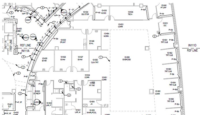
The Interior Side of Revit

Signage

A signage package, which may have its own model depending on the project size, scope and design
schedule, includes sign location plans (Fig. 13), sign elevations and sign schedules for both exterior and
interior signage. We have developed a fully parametric 3D signage library (Fig. 14) that contains
parameters for messages, numbers, pictogram symbols, arrows and other features. Once placed in the
model, signs can report the room they belong to or the adjacent room they are referencing, such as signs
placed in corridors. The families have also parametric dimensions embedded into them such as mounting
height, distance from door frame, offset from walls, etc. and are customized to the client’s preference for
look and functionality.

Fig. 13: Signage families have properties to control room number where it is physically located or
adjacent, mounting heights, offset from door frames and other dimensions.

                                 Fig. 14: Signage families are fully 3D parametric and can be assigned
                                 values for messages, room number, etc.

                                 Signage models are exported to Navisworks, where they can be used to
                                 navigate the project, generating walk-throughs and animations. This is
                                 also a great tool to verify sign locations, messages and direction. The
                                 Navisworks walk-throughs can be shared with other members of the
                                 design team through a video portal (Fig 15). A sample of this can be
                                 watched at http://vimeo.com/user5667300/videos

                                                                                                          10
The Interior Side of Revit
Fig. 15: Navisworks walkthroughs are shared with other team members through a video sharing portal.
11The Interior Side of Revit
The CID: Furniture and Artwork
CID packages typically occur simultaneously with the SID package; however there are projects where the
furniture and artwork selection occurs after the job has started construction. For the most part, furniture
and artwork is a part of the ID/EQ model and is usually placed in its own workset for model opening
purposes. Sometimes, on even larger projects, furniture and artwork have their own model that link with
the architecture and interior models.
A typical CID submission includes furniture/artwork plans, furniture procurement sheets, cost estimate
and room by room lists. Because accountability of the model is a guiding principle of our BIM practices, it
is important that we place every piece of furniture and artwork in the model. The elements of the CID
package are scheduled and exported in database format to be compiled in MS Access, where it is used to
generate detailed reports, produce the procurement sheets, cost estimates and room by room lists.
Each furniture and artwork family includes parameters such as an identification number (called JSN in
government projects), logistic category, specification section, etc. Our library includes both 2D (Fig. 16)
and 3D (Fig. 17) versions of the furniture families and is typically created to match the specific furniture
manufacturer and style chosen for the space. While most of our document production uses the 2D
version of families, the 3D version is utilized for coordination with Navisworks and presentation purposes
(Fig. 18).
Fig. 16: Equipment families in 2D are used for construction document purposes.
Fig. 17: The furniture and equipment 2D families have 3D equivalent versions in a separate library.
12The Interior Side of Revit
Fig. 18: The 3D versions of the equipment families are utilized mainly for presentation purposes. Project:
Irwin Army Community Hospital, Fort Riley, KS
13The Interior Side of Revit
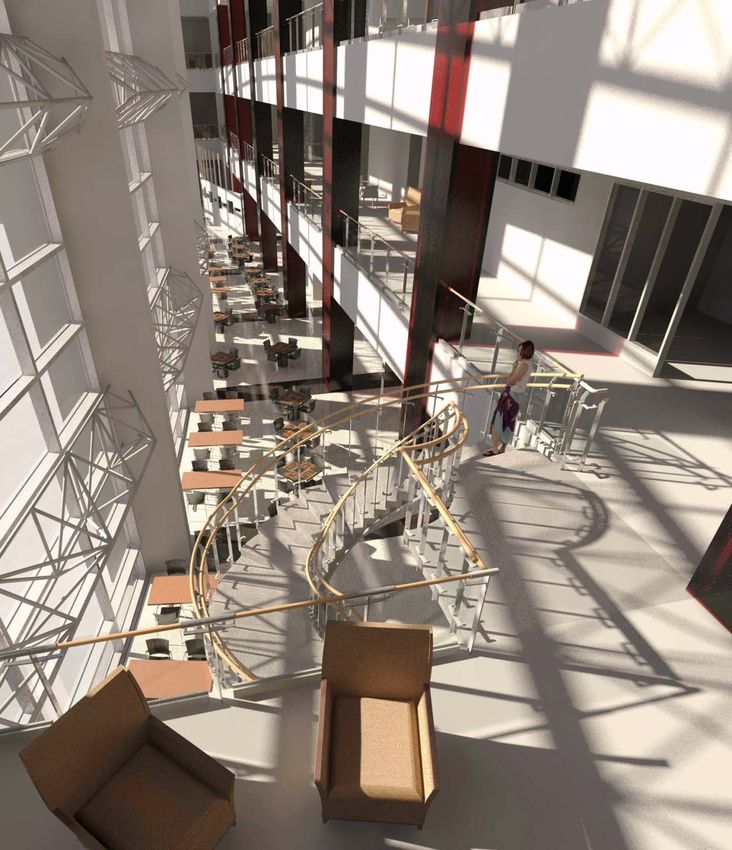
Conclusion
Revit has made the way we create interior design construction documents more efficient and has helped
us provide consistent, quality documents for our clients. One of the greatest benefits has been our ability
to leverage the 3D capabilities of the software to help our clients visualize the end product. We are able to
render an image to near photo quality for presentation and discussion purposes (Fig. 1 and 19). All
materials and finishes are represented accurately and are easy to change with a few clicks. We have
come a long way from the days of AutoCAD. BIM is the way of the future (or should we say the present).
It is a fantastic technology that allows us to work more efficiently and with a greater capability to provide
the client with a more coherent, cohesive and realistic output.
-Damian & Scott
November 2011
14You can also read