User instructions GAZELLE HS GAZELLE HS COMPACT GAZELLE HS COMPACT LOW HEIGHT - (Sliding Door System)
←
→
Page content transcription
If your browser does not render page correctly, please read the page content below
user
    instructions

                GAZELLE HS
         GAZELLE HS COMPACT
    GAZELLE HS COMPACT LOW HEIGHT
          (Sliding Door System)

IM0074 1st Issue 21.05.13
                            1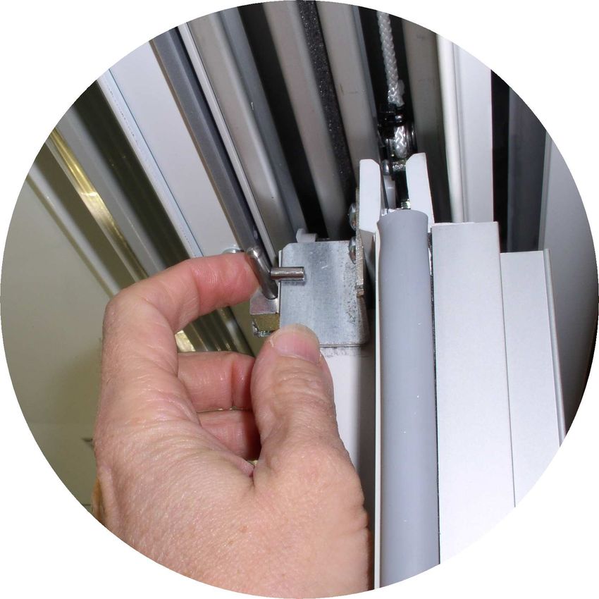
1. INDEX

Chapter                      Content                  Page   Rev.

  1       INDEX                                        2      -

  2       CLASSIFICATION                               3      -

  3       MODEL NAME                                   4      -

  4       INTRODUCTION                                 4      -

  5       SHIPPING, UNPACKING, INSTALLING & STORING    5      -

  6       POSITIONING & RUNNING THE CABINET            5      -

  7       GENERAL DESCRIPTION                          10     -

  8       PROFILES                                     11     -

  9       CABINET HANDLING                             12     -

  10      CLIMATE CONDITIONS                           12     -

  11      FOOT PLANS                                   14     -

  12      TECHNICAL FEATURES                           15     -

  13      USE OF THE CABINET                           16     -

  14      LOADING THE CABINET                          17     -

  15      ORDINARY MAINTENANCE                         18     -

  16      CABINET DISMANTLING AND DISPOSAL             19     -

  17      MANUFACTURERS CONTACT DETAILS                20     -

                                       2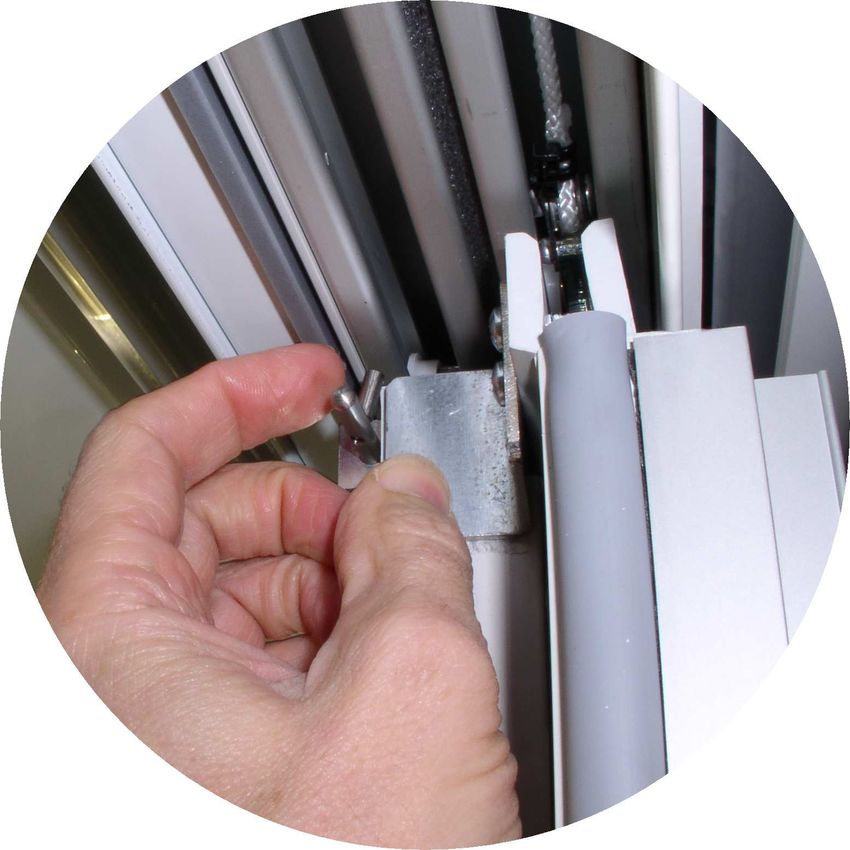
2. CLASSIFICATION

         3
3. MODEL NAME

                                   4. INTRODUCTION

This booklet has been formulated in a simple and rational way to help the reader
fully understand the GAZELLE HS display case. Please, read it carefully and keep
it with the cabinet (fig.1)

                                     fig.1

However, the warning and advice contained in this manual cannot cover every
possible contingency. It is important to underline that common sense, care and
caution cannot be supplied by the manufacturer, but must be provided by those in
charge of its operation and maintenance.

The manufacturer assumes no responsibility for any personal injury or
property damage which may be caused by non-compliance with the
instructions contained in this booklet. Whoever operates the machine must have
read this manual beforehand.

The descriptions and sketches reported in this manual do not bind the manufacturer,
who reserves the right to update them and/or include any upgrading modification of
parts and fittings if deemed necessary for manufacturing or commercial purposes, at
any time and with no previous notice.

Keep this booklet carefully for further consultation.

It is forbidden to reproduce the present manual either totally or partially without
GEORGE BARKER’S written consent.

                                           4
5. SHIPPING, UNPACKING, INSTALLING AND STORING

The case must be shipped and installed as detailed in the separate Installation Manual by
qualified personnel with the correct equipment.

                          6. POSITIONING AND RUNNING THE CABINET

The GAZELLE HS cabinet is only intended for use indoors, within a shop or
supermarket building. Under no circumstances should the case be commissioned
outside in an open environment.

The display case must not be installed in premises containing explosive gas
substances.

6.1 DESCRIPTION

The GAZELLE HS refrigerated display cabinets are available in six different linear
lengths, and the GAZELLE HS Compact and Compact Low are available in five
different linear lengths. The range also includes three different end of island cabinets
for the completion of back-to-back runs as well. The refrigerated display cabinet is
appropriate for the preservation and self service sale of fresh and/or pre-packed
products. Its general description and dimensions are illustrated on page 10, 11 & 12.
As for its weights, crating included and excluded, see tab.l on page 12. A wide
variety of optional accessories are also available for enhanced functions. For more
information, contact the authorized after sales service only.

6.2 TRANSPORTATION

The refrigerated display cabinet is supplied in a package containing a pallet that
enables transportation by the use of fork lifts. Handle the cabinet on its own pallet or
on a similar platform; use a fork lift either manual or electric, provided it is adequate
for handling such appliances and it has the requisite lifting capacity (see page 12 –
fig.3 and tab.l). Handling is reserved for the authorized after-sales service.

6.3 DELIVERY AND STORAGE

Prior to removing the refrigerated display cabinet from the carrier, check the
conditions of the package. If it is showing visible damage, the machine may have
suffered some consequences. If so, unpack the machine in the presence of the
carrier and sign, under protest the delivery bill. The manufacturer assumes no
liability for any damage caused by transportation or wrong handling during storage.
Unpacking is reserved for the authorized after-sales service. Storing temperature
must be between -25°C and +55°C, air humidity between 30% and 95%. Keep the
refrigerated display cabinet safe from direct sunlight and from the elements.

                                            5
6.4 AMBIENT CONDITIONS
The refrigerated display cabinet must not be installed in premises containing
explosive gas substances. It can neither be used in the open nor exposed to the rain.
Before connecting the refrigerated display cabinet make sure that it’s rating plate
data correspond to the features of the existing electrical installation. For correct
operation the refrigerated display cabinet must be placed on a level floor (see page
12 – fig.4), far from sources of heat and/or direct sunlight, doors, windows, fans or
ventilation outlets (see page 12 – fig.5). It must also be granted a reasonable free
front area for customer service.
The refrigerated display cabinet must be housed in a room conforming to the
ambient requirements mentioned on page 12- fig.6 and tab.ll.
IMPORTANT: placing fixed panels on the top of the cabinet is forbidden, as
this part must be accessible for servicing purposes.
6.5 TECHNICAL SPECIFICATIONS
The built-in electrical installation is composed of control devices lodged in the lower
part of the refrigerator. The technical details, which are also reported on the rating
plate, inside the display cabinet are shown in table III, page 15.
The sound level generated by the equipment is below 70dB (A). This refrigerated
cabinet generates no harmful vibrations.
WE HEREBY DECLARE THAT THE DISPLAY CABINET AT ISSUE COMPLIES AS
EXECUTING EEC DIRECTIVE 1935/2003 ON MATERIALS AND OBJECTS WITH
EDIBLES.
6.6 LOADING PRODUCTS
Once the technicians have completed cabinet installation, switch it on through the
isolator/cut off switch. The cabinet will then start its cooling cycle. Allow about two
hours before loading products (fig.15), which must already be at their preservation
temperature. THE DISPLAY CABINET IS FACTORY-REGULATED FOR THE
ANTICIPATED PERFORMANCE.
When loading products make certain that:
• they are similar in size and type;
• for the shelves without stiffeners, the shelf load limit is 225 kg/sq.m for shelves
410-460-510mm and 160 kg/sq.m for shelves 560-610mm. For shelves with
stiffeners the shelf load limit is 300 kg/sq.m for shelves 410-460-510mm and 210
kg/sq.m for shelves 560-610mm.
• products do not cover the air return grille (see fig.7, page 16).
6.7 USE
This refrigerated display case was designed and manufactured exclusively for the
display of fresh pre-packed food, drinks and dairies. The case is aimed for the
6conservation of food temperature, not for lowering it. When introduced, the
foodstuffs must be at their conservation temperature.
WARNING: It is possible to enter the electronic programming of the refrigerated
display cabinet. SUCH ACTIONS ARE RESERVED FOR THE TECHNICAL PERSONNEL.
6.8 PRESCRIPTIONS AND RESTRICTIONS
KEEPING PHARMACEUTICAL PRODUCTS IN THE DISPLAY CABINET IS STRICTLY
FORBIDDEN (fig.8).
DO NOT REMOVE protections or panels when it requires the use of tools. IN
PARTICULAR, DO NOT REMOVE THE ELECTRIC CONTROL BOARD COVER.
Do not expose the display case to atmospheric agents (fig.13). DO NOT STEP on the
cabinet bumper rail. DO NOT STEP ON THE TOP OF THE CABINET AND DO NOT LAY
WEIGHTS ON IT (fig.9).
Do not spill water directly or indirectly on the display case (fig.11). Do not touch the
equipment with damp or wet hands or feet; do not use it while barefoot (fig.12).
ANY OTHER USE NOT EXPRESSLY MENTIONED IN THIS BOOKLET MUST BE
CONSIDERED AS HAZARDOUS. THE MANUFACTURER ASSUMES NO RESPONSIBILITY
FOR ANY DAMAGE RESULTING FROM IMPROPER, INCORRECT OR UNREASONABLE
USE.
6.9 ORDINARY MAINTENANCE
ATTENTION! BEFORE STARTING ANY MAINTENANCE OR CLEANING, DISCONNECT
THE REFRIGERATOR FROM THE ELECTRICAL POWER SUPPLY BY THE CABINET
ISOLATOR (fig.2).
IMPORTANT: During maintenance or cleaning operations, be sure that the light in the
working area is sufficient and if necessary, use an additional source of light.
CLEANING THE REFRIGERATED DISPLAY CASE
1) Every week clean the outer surfaces of the display case with mild soap or
detergent in lukewarm water only. Wipe carefully with a soft cloth. Never clean
it using inflammable or scouring agents, alcohol, acetone or solvents. NEVER
CLEAN THE DISPLAY CASE BY THE USE OF WATER JETS. Clean glass surfaces
using glass-cleaning products only.
CAUTION! NEVER WASH OR CLEAN THE UPPER PART OF THE DISPLAY CASE WITH
WATER OR LIQUIDS
2) Every month clean the inside surfaces following the instructions provided in the
preceding item:
73) Defrost the display case every three months to let the ice that may have formed
between the fins melt. Frost may otherwise prevent correct operation. Proceed as
follows.
Disconnect the display case from the electrical power supply by the cabinet isolator
(fig.2).
Empty the display cabinet, store the contents in cold rooms or refrigerators that are
suitable for preserving and maintaining product at the required temperature.
Wait until the cold room has reached ambient temperature.
Clean the inside of the display case thoroughly with mild soap or detergent and
lukewarm water. Wipe carefully with a soft cloth.
After having carefully checked that the display case is completely dry inside, start
the appliance again by the cabinet isolator.
Allow a couple of hours before loading the products back again.
Attention! Disassemble and assemble very slowly, using heavy-duty gloves. It is
advisable to have these cleaning operations carried out by authorized service
personnel.
ANY MAINTENANCE OPERATION NOT INCLUDED AMONG THE FORMER STEPS MUST
BE CARRIED OUT BY THE AUTHORISED AFTER-SALES SERVICE OR BY QUALIFIED
PERSONNEL.
CANOPY AND SHELF LIGHTING: canopy and shelf lamps must be replaced by the
after-sales service only. Resort to it if need be.
If you should wish to eliminate shelf lighting, let it be done by the authorised after-
sales service.
6.10 EMERGENCY SITUATIONS
a) The display case will not start or will not keep on working:
• there may be a general black-out;
• the wall main switch may be off.
If power failure is not due to any of the above causes, call the nearest after-sales
service immediately, empty the display case and store the foods in cold rooms or
refrigerators that may ensure preservation temperature.
b) The display case will not cool properly:
• make sure that the product load is correct and the air slots are not covered;
• defrost and clean it before starting normal operation (see chapter 6);
• make sure that the case is not exposed to sources of heat or draught;
• check that the display case is perfectly horizontal by the use of a spirit level. Make
certain that ambient conditions comply with the requirements of fig.5-6 on page 12.
Should insufficient cooling persist, resort to the nearest after-sales service.
c) The cabinet operates noisily:
• Make sure that screws and bolts are closed tight;
• Check that the display case is perfectly horizontal by the use of a spirit level.
IN CASE OF A GAS LEAK OR FIRE, do not breathe inside the room that houses the
display case before having aired it properly. Turn the display cabinet off by the
8isolator switch behind the lift up flap (see fig.2) DO NOT USE WATER BUT ONLY DRY
EXTINGUISHERS TO FIGHT THE FIRE.
6.11 AFTER-SALES SERVICE
Should it be necessary to resort to technical assistance, contact your sales person
immediately. If spare parts are needed, always refer to your after-sales service:
insist on the use of original spare parts. Scroll the Italian and European network of
branch offices on the back of this manual for addresses and phone numbers.
6.12 DISMANTLING AND DISPOSAL
For the sake of the environment, please sort the parts and materials composing the
display case in accordance with the waste disposal provisions in force in your
country, so that they can be properly disposed of or recycled. All its parts cannot be
treated as household waste, except for the metal parts, which nevertheless are not
considered as special waste in most European countries.
THE PARTS COMPOSING THE REFRIGERATING CIRCUIT MUST NOT BE SEVERED OR
SEPARATED BUT DELIVERED INTACT TO A CENTRE SPECIALISED IN RECYCLING
REFRIGERANT GAS.
REFRIGERANT DISPOSAL CONSIDERATIONS
Classification:
This material and/or its container must be disposed of as hazardous waste.
Disposal Considerations:
Do not discharge into drains or the environment; dispose to an authorized waste
collection point.
97. GENERAL DESCRIPTION
fig.2
108. PROFILES
GAZELLE HS
PROFILES
GAZELLE HS GAZELLE HS COMPACT
CROSS SECTION CROSS SECTION
100
100
1040 740
807 507
600 450
1611 1581 1611 1581
2090 mid 2090 mid
±15mm ±15mm
undercase clearance
undercase clearance
±15mm
±15mm
760 460
125
125
362 mid 362 mid
±15mm ±15mm
988 688
1040 740
GAZELLE HS COMPACT LOW HEIGHT
CROSS SECTION
100
740
507
450
1174 1144
1653 mid
±15mm
undercase clearance
±15mm
460
125
362 mid
±15mm
688
740
119. CABINET HANDLING
fig.3
tab.l
10. CLIMATE CONDITIONS
fig.4 fig.5
fig.6
tab.ll
1211. FOOT PLANS
GAZELLE HS
POSITION OF FEET
1311. FOOTPLANS
GAZELLE HS COMPACT & GAZELLE HS COMPACT LOW HEIGHT
POSITION OF FEET
1412. TECHNICAL FEATURES
tab.lll
1513. USE OF THE CABINET
fig.7
fig.8
fig.10
fig.9
fig.11 fig.13
fig.12
1614. LOADING THE CABINET
The Sliding Doors can be mechanically
held open while the cabinet is being
restocked. To enable this, the self
closing mechanism needs to be
temporarily disabled.
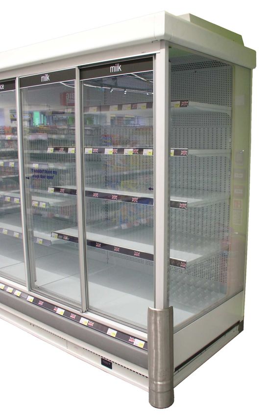
1. Slide two doors
together, the locking
pin is located at the
top of the door.
2. Rotate the pin
through 90° to
temporarily lock the
doors together.
3. When finished
restocking, the pin should
be returned to the vertical
position, enabling the
doors to automatically
close again.
fig.14
1715. ORDINARY MAINTENANCE
fig.15 fig.16
fig.17
1816. CABINET DISMANTLING AND DISPOSAL
Before removing and transporting cabinets for end of life disposal the refrigerant must be removed by
a competent engineer.
All materials must be disposed of by competent personnel using a method in line with current local
rules and regulations.
(For the sake of the environment, please sort the display case parts and materials in accordance with
the waste disposal provisions in force in your country, so that they can be properly disposed of or
recycled. No parts can be treated as household waste, except for the metal parts which are not
considered as special waste in most European countries.
REFRIGERANT DISPOSAL CONSIDERATIONS
Classification
This material and/or its container must be disposed of as hazardous waste.
Disposal Considerations
Do not discharge into drains or the environment, dispose to an authorized waste
collection point.
1917. MANUFACTURERS CONTACT DETAILS
GAZELLE HS cabinet manufactured by:
George Barker – Epta UK
Highfield Works – Highfield Road – Bradford BD10 8RU
Tel +44 (0)1274 703200 – Fax +44 (0)1274 615916
24hour Customer Service Tel 0870 120 0070
e-mail: ServiceCenterBradford@eptarefrigeration.com
20You can also read