THE SIMULATION PLATFORM FOR POWER ELECTRONIC SYSTEMS - RT Box User Manual January 2021 - Plexim
←
→
Page content transcription
If your browser does not render page correctly, please read the page content below
THE SIMULATION PLATFORM FOR
POWER ELECTRONIC SYSTEMS

RT Box User Manual January 2021
How to Contact Plexim:

%   +41 44 533 51 00             Phone
    +41 44 533 51 01             Fax
)   Plexim GmbH                  Mail
    Technoparkstrasse 1
    8005 Zurich
    Switzerland
@   info@plexim.com              Email
    http://www.plexim.com        Web

    RT Box User Manual
    © 2021 by Plexim GmbH
    The product described in this manual is furnished under a license agreement.
    The software may be used or copied only under the terms of the license agree-
    ment. No part of this manual may be photocopied or reproduced in any form
    without prior written consent from Plexim GmbH.
    PLECS is a registered trademark of Plexim GmbH. MATLAB, Simulink and
    Simulink Coder are registered trademarks of The MathWorks, Inc. Bonjour
    is a registered trademark of Apple, Inc. Other product or brand names are
    trademarks or registered trademarks of their respective holders.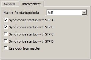
Contents

Contents                                                                               iii

1 Quick Start                                                                           3
  Requirements . . . . . . . . . . . . . . . . . . . . . . . . . . . . . . . . . .      3
  Install the Target Support Package . . . . . . . . . . . . . . . . . . . . .          3
  Set up Zeroconf . . . . . . . . . . . . . . . . . . . . . . . . . . . . . . . . .     3
  Connect the RT Box . . . . . . . . . . . . . . . . . . . . . . . . . . . . . .        4
  Upload a Model . . . . . . . . . . . . . . . . . . . . . . . . . . . . . . . . .      4
  Start the External Mode . . . . . . . . . . . . . . . . . . . . . . . . . . . .       5
  Shutdown . . . . . . . . . . . . . . . . . . . . . . . . . . . . . . . . . . . . .    6
  Next Steps . . . . . . . . . . . . . . . . . . . . . . . . . . . . . . . . . . . .    6

2 Setting up the RT Box                                                                 7
  Network Configuration . . . . . . . . . . . . . . . . . . . . . . . . . . . . .       7
       Setting the hostname . . . . . . . . . . . . . . . . . . . . . . . . . . .       7
       Using dynamically assigned IP addresses (DHCP) . . . . . . . . . .               8
       Using static IP addresses . . . . . . . . . . . . . . . . . . . . . . . .        8
  Firmware Update . . . . . . . . . . . . . . . . . . . . . . . . . . . . . . . .       9
  Automatic Start of an Executable . . . . . . . . . . . . . . . . . . . . . .         10
Contents
3 RT Box Architecture 11
Front Panel . . . . . . . . . . . . . . . . . . . . . . . . . . . . . . . . . . . 11
Analog Inputs . . . . . . . . . . . . . . . . . . . . . . . . . . . . . . . 11
Analog Outputs . . . . . . . . . . . . . . . . . . . . . . . . . . . . . . 14
Digital Inputs . . . . . . . . . . . . . . . . . . . . . . . . . . . . . . . 15
Digital Outputs . . . . . . . . . . . . . . . . . . . . . . . . . . . . . . 17
Resolver . . . . . . . . . . . . . . . . . . . . . . . . . . . . . . . . . . 18
Rear Panel . . . . . . . . . . . . . . . . . . . . . . . . . . . . . . . . . . . . 20
CAN . . . . . . . . . . . . . . . . . . . . . . . . . . . . . . . . . . . . . 20
UART . . . . . . . . . . . . . . . . . . . . . . . . . . . . . . . . . . . . 20
Displayport . . . . . . . . . . . . . . . . . . . . . . . . . . . . . . . . . 21
Industrial Ethernet . . . . . . . . . . . . . . . . . . . . . . . . . . . . 22
Grounding Concept . . . . . . . . . . . . . . . . . . . . . . . . . . . . . . . 22
Principle of Operation . . . . . . . . . . . . . . . . . . . . . . . . . . . . . 23
Execution of the Real-time Application . . . . . . . . . . . . . . . . 23
4 Specifications 25
Overview . . . . . . . . . . . . . . . . . . . . . . . . . . . . . . . . . . . . . 25
Mechanical Dimensions . . . . . . . . . . . . . . . . . . . . . . . . . . . . 27
RT Box 1 . . . . . . . . . . . . . . . . . . . . . . . . . . . . . . . . . . 27
RT Box 2 . . . . . . . . . . . . . . . . . . . . . . . . . . . . . . . . . . 27
RT Box 3 . . . . . . . . . . . . . . . . . . . . . . . . . . . . . . . . . . 28
5 RT Box Coder Options 31
6 Distributed Realtime Simulation 33
Model Setup for Distributed Realtime Simulation . . . . . . . . . . . . . 33
Identifying Suitable Subsystems . . . . . . . . . . . . . . . . . . . . 33
Exchanging signals between two models . . . . . . . . . . . . . . . 34
Signal relaying . . . . . . . . . . . . . . . . . . . . . . . . . . . . . . 35
Time and Startup Synchronization . . . . . . . . . . . . . . . . . . . . . . 35
Synchronized versus Unsynchronized Simulation . . . . . . . . . . 36
ivContents
7 Scripting 39
Establishing an XML-RPC Connection to the RT Box . . . . . . . . 39
Overview of XML-RPC Commands . . . . . . . . . . . . . . . . . . . 39
Example Script . . . . . . . . . . . . . . . . . . . . . . . . . . . . . . 42
8 RT Box Target Support Library Component Reference 43
Analog In . . . . . . . . . . . . . . . . . . . . . . . . . . . . . . . . . . . . . 44
Analog Out . . . . . . . . . . . . . . . . . . . . . . . . . . . . . . . . . . . . 45
CAN Receive . . . . . . . . . . . . . . . . . . . . . . . . . . . . . . . . . . . 46
CAN Transmit . . . . . . . . . . . . . . . . . . . . . . . . . . . . . . . . . . 47
Data Capture . . . . . . . . . . . . . . . . . . . . . . . . . . . . . . . . . . 49
Digital In . . . . . . . . . . . . . . . . . . . . . . . . . . . . . . . . . . . . . 50
Digital Out . . . . . . . . . . . . . . . . . . . . . . . . . . . . . . . . . . . . 51
Incremental Encoder . . . . . . . . . . . . . . . . . . . . . . . . . . . . . . 52
Programmable Value . . . . . . . . . . . . . . . . . . . . . . . . . . . . . . 54
PWM Capture . . . . . . . . . . . . . . . . . . . . . . . . . . . . . . . . . . 55
PWM Out . . . . . . . . . . . . . . . . . . . . . . . . . . . . . . . . . . . . . 56
PWM Out (Variable) . . . . . . . . . . . . . . . . . . . . . . . . . . . . . . 58
Quadrature Encoder Counter . . . . . . . . . . . . . . . . . . . . . . . . . 62
Resolver In . . . . . . . . . . . . . . . . . . . . . . . . . . . . . . . . . . . . 65
Resolver Out . . . . . . . . . . . . . . . . . . . . . . . . . . . . . . . . . . . 67
SFP In . . . . . . . . . . . . . . . . . . . . . . . . . . . . . . . . . . . . . . 68
SFP Out . . . . . . . . . . . . . . . . . . . . . . . . . . . . . . . . . . . . . 69
SPI Master . . . . . . . . . . . . . . . . . . . . . . . . . . . . . . . . . . . . 70
To File . . . . . . . . . . . . . . . . . . . . . . . . . . . . . . . . . . . . . . 73
UDP Receive . . . . . . . . . . . . . . . . . . . . . . . . . . . . . . . . . . . 75
UDP Send . . . . . . . . . . . . . . . . . . . . . . . . . . . . . . . . . . . . 76
Wall Clock . . . . . . . . . . . . . . . . . . . . . . . . . . . . . . . . . . . . 77
1Contents 2
1

            Quick Start

Requirements
            In order to operate your RT Box you need
            • a host computer (with Microsoft Windows, Mac OS X or Linux),
            • PLECS Blockset or Standalone 4.5 or newer and
            • PLECS Coder.
            If you have not done so yet, please download and install the latest PLECS re-
            lease on your host computer.

Install the Target Support Package
            Download the appropriate ZIP archive from the web page
            www.plexim.com/download/rt_box, extract it and move the folder
            PLECS_RT_Box e.g. to HOME/Documents/PLECS/CoderTargets. In PLECS,
            choose the entry Preferences... from the File menu (PLECS menu on Mac
            OS X) to open the PLECS Preferences dialog.
            On the Coder tab click on the Change button and select the folder HOME/Doc-
            uments/PLECS/CoderTargets. The RT Box Target should now be listed under
            Installed targets.

Set up Zeroconf
            The RT Box uses the Zero Configuration Networking (Zeroconf) protocol to fa-
            cilitate network communication without the aid of additional network servers.
            To use Zeroconf, the corresponding software components are required on your
1 Quick Start
host computer (which runs PLECS). It is also possible to use the RT Box with-
out Zeroconf, but this requires additional steps for assigning an IP address,
see “Network Configuration” (on page 7).
On Mac OS X, Zeroconf is integrated into the operating system.
On Linux, the avahi daemon and the libdnssd compatibility library must be
installed. On Debian/Ubuntu Linux, the corresponding packages are named
avahi-daemon and libavahi-compat-libdnssd1.
On Windows, Zeroconf is available through Apple’s Bonjour drivers, which
may already be installed on your computer. Alternatively, you can install the
appropriate mDNSInstaller package that is bundled with the Target Sup-
port Package. You find the 32-bit and 64-bit installer packages in the folder
PLECS_RT_Box/bin/win.
Connect the RT Box
Use an Ethernet cable to connect the RT Box to your local network or – if
your host computer supports Zeroconf – directly to an Ethernet port on your
host computer.
Turn on the RT Box by flicking the power switch on the rear panel. The green
Power LED at the front panel will turn on. When the RT Box has acquired a
dynamic IP address from a DHCP server on the network, it will turn on the
green Ready LED to indicate that it is ready to communicate.
Note The Ready LED will not turn on if you have connected the box directly
with your host computer so that it uses a self-assigned IP address.
To test the network connection, open a web browser on the host computer and
enter the address http://rtbox-0123456789ab.local, where 0123456789ab is
the MAC address of the RT Box (without colons), which you find on a sticker
below the SD card slot on the back.
Upload a Model
In PLECS, choose the entry Demo Models from the Window menu to open
the PLECS Demo Model Library. Open the demo model Basic Topologies /
Boost converter and save it e.g. as HOME/Documents/PLECS/Boost-RT.plecs.
4Start the External Mode
In order to generate code for the complete model, open the Coder Options di-
alog by choosing the entry Coder options... from the Coder menu. In the
General tab set the Discretization step size parameter to e.g. 1e-5.
Now select the Target tab and switch the Target selector from Generic to ei-
ther PLECS RT Box 1, PLECS RT Box 2 or PLECS RT Box 3 depending on which
target the model should later run. If this option is not available, the RT Box
Support Package has not been installed correctly (see “Install the Target Sup-
port Package” on page 3).
In the Target device field, enter the address of your RT Box. If your host
computer supports Zeroconf, a button marked ... appears next to this field. A
click on this button opens a browser that shows the RT Boxes that are visible
in the network.
Click on the Build button at the bottom of the Coder Options dialog to start
the build process. This will generate the C code for the model, compile it and
upload it to the RT Box. After the successful upload, the blue Running LED
on the front panel of the RT Box will turn on to indicate that the real-time
application is running.
Start the External Mode
Select the External Mode tab of the Coder Options dialog and click on the
Connect button. Set the Number of samples parameter to e.g. 200 and click
on the Start autotriggering button. PLECS will now capture the real-time
signals of the Ammeter and Voltmeter in the model running on the RT Box
and display them on the Scope in your PLECS model.
You can synchronize the data capture to a specific trigger event. To do so, set
the Trigger channel selector from Off to the desired signal. The Scope will
now show a small square indicating the trigger level and delay. If the level
or delay are outside the current axes limits, a small triangle will be shown
instead. Drag the trigger icon to change the trigger level; drag it with the left
mouse-button pressed to change the trigger delay. Both parameters can also
be set in the External Mode dialog.
Note While a trigger channel is active, the Scope signals are only updated
when a trigger event is detected.
51 Quick Start
While the PLECS model is connected to the RT Box, the model is locked
against modifications. To disconnect from the RT Box, click on the Discon-
nect button or close the Coder Options dialog.
Shutdown
To turn off the RT Box, simply flip the power switch on the rear panel.
Next Steps
To connect the real-time application with real-world I/O signals, use the blocks
from the PLECS RT Box library in the PLECS Library Browser. For in-
stance, to use a digital input channel as the gate signal for the FET, replace
the Pulse Generator with a Digital In block (see page 50). To feed the current
and/or voltage measurement back to an external controller via an analog out-
put channel, use an Analog Out block (see page 45) and connect it to the de-
sired meter.
62
Setting up the RT Box
Network Configuration
Communication with the RT Box is done via Ethernet. The box is identified
either by its IP address or by a unique hostname. The RT Box supports Zero
Configuration Networking (Zeroconf) to allow identifying the box by its host-
name without any additional network servers (see “Set up Zeroconf ” on page
3).
Three networking scenarios are supported by the RT Box:
• Dynamically assigned IP addresses: The RT Box is connected to a larger
network and receives an IP address from an external DHCP server. Name
resolution is done by an external DNS server or optionally by using Zero-
conf.
• Static IP address: A fixed IP address is assigned to the RT Box. The box
can be accessed by its IP address. Name resolution is done by an external
DNS server or optionally by using Zeroconf.
• Self-assigned IP address: The RT Box is connected directly to a PC with no
additional network infrastructure. Both the RT Box and the PC use auto-
matically assigned IP addresses. Address assigning and name resolution is
done by Zeroconf, the installation of a Zeroconf driver is mandatory.
Setting the hostname
Since the IP address of the RT Box is typically not known it is more conve-
nient to access the box by its hostname. By default the hostname is set to
the MAC address (without colons) with the prefix rtbox-, for example rtbox-
20b0f70361c2. The MAC address is printed on a sticker below the SD card
slot on the backside of the RT Box. A custom hostname can be set by creating2 Setting up the RT Box
a text file named hostname in the directory /config/etc on the SD card of the
RT Box. The file should contain a single line with the custom hostname.
Using dynamically assigned IP addresses (DHCP)
By default the RT Box is configured to use a dynamically assigned IP address
from a DHCP server. No additional setup is necessary for this scenario.
After the box has been switched on the green Ready LED will turn on when
the box has acquired an IP address from the DHCP server and is ready for
communication.
If the box was previously configured with a static IP address it
can be reconfigured to use dynamic address by removing the file
/config/etc/network/interfaces from the SD card.
Using static IP addresses
Follow these steps for configuring the RT Box using static IP addresses:
1 Choose a suitable private IP subnet. For example, enter 192.168.0.3 for
the RT Box and choose 192.168.0.2 for the host computer.
2 Create a text file with the following structure with your specific addresses
(the parameters):
auto lo
iface lo inet loopback
auto eth0
# IPv4 addres: all parameters except for 'address' and 'netmask' are optional
iface eth0 inet static
address 192.168.0.3
netmask 255.255.255.0
network 192.168.0.0
broadcast 192.168.0.255
gateway 192.168.0.1
The file must be named interfaces and be placed in the directory
/config/etc/network on the SD card of the RT Box.
3 Plug the ethernet cable of the RT Box to either an ethernet port or an eth-
ernet adapter of the host computer and boot the RT Box.
8Firmware Update
4 For Windows:
Open the “Network and Sharing Center” in the Windows Control Panel
and click on the appropriate connection.
In the “Local Area Connection x Status” window, click on Properties.
In the “Local Area Connection x Properties” window, double-click on In-
ternet Protocol Version 4 (TCP/IPv4).
In the “Internet Protocol Version 4 (TCP/IPv4) Properties” window,
configure the static IP address of the host computer. For example, enter
192.168.0.2 as the “IP address” and 255.255.255.0 as the “Subnet mask”.
5 For Mac:
“Open Network Preferences” and select the appropriate interface with a
new “Service Name”.
“Manually” configure the IPv4 of the host computer. For example, enter
192.168.0.2 as the “IP address” and 255.255.255.0 as the “Subnet mask”.
6 The RT Box should now be listed when clicking the Browse RT Boxes
button. The RT Box can be targeted by entering the chosen static IP ad-
dress of the RT Box, for example, enter 192.168.0.3 or the hostname
rtbox-xyz.local as the Target Device in the Coder Options dialog.
Firmware Update
The firmware of the RT Box is stored on a SD Card which is accessible on the
back side of the box. The version of the installed firmware is displayed in the
Info tab in the RT Box web interface.
Follow these steps for updating the firmware:
1 Make sure that the latest version of the target support package is installed
on your PC. The target support package is available from the Plexim web-
site.
2 Turn off the RT Box. Remove the SD Card from the slot on the back of the
box by pushing it in.
3 Put the card into an SD card reader connected to your PC.
4 Locate the new firmware: Open the directory containing the target support
package, then open the folder PLECS_RT_Box\firmware. It contains a
92 Setting up the RT Box
sub-directory versionnumber, e.g. 1.0.0. The firmware files are the two files
image.ub and BOOT.BIN in this directory.
5 Copy the two files image.ub and BOOT.BIN to the root directory of the SD
card.
6 Eject the SD card and remove it from the card reader.
7 Place the SD card back into the slot on the back of the RT Box.
8 Turn on the box and reload the web interface of the RT Box in your web
browser. The new firmware version should be displayed in the Info tab of
the RT Box Web Interface.
Automatic Start of an Executable
It is possible to automatically run an executable directly after the startup of
the RT Box. This option is useful if an RT Box should always run the same
model or if no connection to a host PC is available.
Follow these steps to configure the box for this purpose:
1 Leave the target device field of the Target tab in the PLECS Coder op-
tions empty and generate code.
2 Open the output directory that is specified in the General tab of the
PLECS Coder options.
3 Rename the file modelname.elf to autostart.elf and copy it to the root
directory of the SD card which also contains the RT Box firmware.
4 Reboot the RT Box with the same SD card. The model will start after the
RT Box has booted up.
103
RT Box Architecture
This chapter describes the hardware architecture of the RT Box 1, 2 and 3.
Most of the following properties are common to all versions of the RT Box.
Differences between versions are specifically mentioned in the following sec-
tions.
Front Panel
The front panel of the RT Box contains connectors for the analog and digital
inputs and outputs (I/Os). For RT Box 1 and 2 there are four of these connec-
tors whereas the RT Box 3 has eight. The I/Os need to be connected by the
user to the device-under-test (DUT). If the RT Box is employed for HIL sim-
ulations, the DUT is the real control hardware and the RT Box emulates the
plant. If the RT Box is used for rapid control prototyping, the DUT is the real
plant controlled by the RT Box.
All I/O connectors are 37 pin normal-density D subminiature (D-Sub) connec-
tors. Male connectors are used for inputs while female ones are used for out-
puts.
In addition, the front panel of the RT Box 1 contains 4 LEDs to indicate the
status of the box. For the RT Box 2 and 3 the status of the box is shown in an
interactive display.
Analog Inputs
The RT Box 1 and 2 provide 16 analog input channels the RT Box 3 provides
32 thereof. The input voltage range can be set for all channels together to ei-
ther ±10 V or ±5 V. Each channel can be individually configured for differen-
tial or single-ended measurement.3 RT Box Architecture
The analog-to-digital converters (ADCs) inside the RT Box are specified for
a maximum sampling rate of 2 MSPS with no-cycle latency for the RT Box 1
and a maximum sampling rate of 3 MSPS with no-cycle latency for the RT Box
2 and 3. As the firmware of the RT Box currently limits the cycle time to a
minimum of 1 µs, a sampling rate of up to 1 MSPS can be realized.
The analog inputs play an important role when the RT Box is used for rapid
control prototyping. To allow instantaneous sampling of the input signals, the
analog inputs do not have internal anti-aliasing filters. If the bandwidth of
the input signal shall be limited, such filters must be added externally.
Differential measurement
The analog inputs are equipped for fully differential measurement. The mea-
sured voltage is the difference between the positive and the negative input.
The full-scale differential input range is ±10 V or ±5 V, depending on the con-
figuration.
A ground connection between the DUT and the RT Box is required even in dif-
ferential mode, because the inputs cannot float freely with respect to GND.
For linear operation, the input voltages referenced to GND shall not exceed
±10.8 V. As a consequence, the acceptable common mode voltage range is
±5.8 V (for ±10 V operation) and ±8.3 V (for ±5 V operation).
Single-ended measurement
To configure an input channel for single-ended measurement, only the positive
input is used for signal measurement while the corresponding negative input
is clamped to GND. The full-scale input voltage range is either ±10 V or ±5 V,
depending on the configuration.
Analog Input Connector
1 19
20 37
37 pin male D-Sub (front view)
12Front Panel
Pinout of the analog input connector. *The value in brackets (x) specifies the
channel number for the second analog input connector of the RT Box 3
Pin Description* Pin Description
1 Analog input 0 (16) positive 20 Analog input 0 (16) negative
2 Analog input 1 (17) positive 21 Analog input 1 (17) negative
3 Analog input 2 (18) positive 22 Analog input 2 (18) negative
4 Analog input 3 (19) positive 23 Analog input 3 (19) negative
5 Analog input 4 (20) positive 24 Analog input 4 (20) negative
6 Analog input 5 (21) positive 25 Analog input 5 (21) negative
7 Analog input 6 (22) positive 26 Analog input 6 (22) negative
8 Analog input 7 (23) positive 27 Analog input 7 (23) negative
9 Analog input 8 (24) positive 28 Analog input 8 (24) negative
10 Analog input 9 (25) positive 29 Analog input 9 (25) negative
11 Analog input 10 (26) positive 30 Analog input 10 (26) negative
12 Analog input 11 (27) positive 31 Analog input 11 (27) negative
13 Analog input 12 (28) positive 32 Analog input 12 (28) negative
14 Analog input 13 (29) positive 33 Analog input 13 (29) negative
15 Analog input 14 (30) positive 34 Analog input 14 (30) negative
16 Analog input 15 (31) positive 35 Analog input 15 (31) negative
17 n/c 36 n/c
18 n/c 37 GND
19 n/c Shield PE
133 RT Box Architecture
Analog Outputs
The 16 analog output channels of the RT Box are heavily used for HIL sim-
ulations. The analog outputs provide the voltage signals from sensors inside
the simulated plant and need to be connected to the analog inputs of the con-
troller.
The full-scale voltage range of the outputs can be set to ±10 V, 0 . . . 10 V, ±5 V
and 0 . . . 5 V.
For testing purposes, the analog outputs can be connected with the analog in-
puts of the same or a different RT Box using a 37 pin D-Sub extension cable.
Analog Output Connector
19 1
37 20
37 pin female D-Sub (front view)
Pinout of the analog output connector. *The value in brackets (x) specifies the
channel number for the second analog output connector of the RT Box 3
Pin Description* Pin Description
1 Analog output 0 (16) 20 GND
2 Analog output 1 (17) 21 GND
3 Analog output 2 (18) 22 GND
4 Analog output 3 (19) 23 GND
5 Analog output 4 (20) 24 GND
6 Analog output 5 (21) 25 GND
7 Analog output 6 (22) 26 GND
8 Analog output 7 (23) 27 GND
9 Analog output 8 (24) 28 GND
10 Analog output 9 (25) 29 GND
14Front Panel
(contd.) Pinout of the analog output connector. *The value in brackets (x)
specifies the channel number for the second analog output connector of the
RT Box 3
Pin Description* Pin Description
11 Analog output 10 (26) 30 GND
12 Analog output 11 (27) 31 GND
13 Analog output 12 (28) 32 GND
14 Analog output 13 (29) 33 GND
15 Analog output 14 (30) 34 GND
16 Analog output 15 (31) 35 GND
17 n/c 36 n/c
18 n/c 37 GND
19 n/c Shield PE
Digital Inputs
Active bus hold circuitry holds unused or floating data inputs at a valid logic
level. If a specific logic level is required for high-impedance inputs, pull-down
or pull-up resistors must be connected externally.
Digital Input Connector
1 19
20 37
37 pin male D-Sub (front view)
153 RT Box Architecture
Pinout of the digital input connector. *The value in brackets (x) specifies the
channel number for the second digital input connector of the RT Box 3.
Pin Description Pin Description
1 Digital input 0 (32) 20 Digital input 1 (33)
2 Digital input 2 (34) 21 Digital input 3 (35)
3 Digital input 4 (36) 22 Digital input 5 (37)
4 Digital input 6 (38) 23 Digital input 7 (39)
5 GND 24 Digital input 8 (40)
6 Digital input 9 (41) 25 Digital input 10 (42)
7 Digital input 11 (43) 26 Digital input 12 (44)
8 Digital input 13 (45) 27 Digital input 14 (46)
9 Digital input 15 (47) 28 GND
10 Digital input 16 (48) 29 Digital input 17 (49)
11 Digital input 18 (50) 30 Digital input 19 (51)
12 Digital input 20 (52) 31 Digital input 21 (53)
13 Digital input 22 (54) 32 Digital input 23 (55)
14 GND 33 Digital input 24 (56)
15 Digital input 25 (57) 34 Digital input 26 (58)
16 Digital input 27 (59) 35 Digital input 28 (60)
17 Digital input 29 (61) 36 Digital input 30 (62)
18 Digital input 31 (63) 37 GND
19 5 V, 1.5 A max. Shield PE
16Front Panel
Digital Outputs
Digital Output Connector
19 1
37 20
37 pin female D-Sub (front view)
Pinout of the digital output connector. *The value in brackets (x) specifies the
channel number for the second digital output connector of the RT Box 3.
Pin Description Pin Description
1 Digital output 0 (32) 20 Digital output 1 (33)
2 Digital output 2 (34) 21 Digital output 3 (35)
3 Digital output 4 (36) 22 Digital output 5 (37)
4 Digital output 6 (38) 23 Digital output 7 (39)
5 GND 24 Digital output 8 (40)
6 Digital output 9 (41) 25 Digital output 10 (42)
7 Digital output 11 (43) 26 Digital output 12 (44)
8 Digital output 13 (45) 27 Digital output 14 (46)
9 Digital output 15 (47) 28 GND
10 Digital output 16 (48) 29 Digital output 17 (49)
11 Digital output 18 (50) 30 Digital output 19 (51)
12 Digital output 20 (52) 31 Digital output 21 (53)
13 Digital output 22 (54) 32 Digital output 23 (55)
14 GND 33 Digital output 24 (56)
15 Digital output 25 (57) 34 Digital output 26 (58)
16 Digital output 27 (59) 35 Digital output 28 (60)
173 RT Box Architecture
(contd.) Pinout of the digital output connector. *The value in brackets (x) spec-
ifies the channel number for the second digital output connector of the RT Box
3.
Pin Description Pin Description
17 Digital output 29 (61) 36 Digital output 30 (62)
18 Digital output 31 (63) 37 GND
19 n/c Shield PE
Resolver
The RT Box 2 and 3 provide a resolver interface that can be used for
Hardware-in-the-loop (HIL) and Rapid Control Prototyping (RCP) applications.
Resolver In connector (RCP)
1 5
6 9
9 pin male D-Sub (front view)
Pinout of Resolver In connector
Pin Description
1 GND
2 +COSIN
3 +SININ
4 +EXCOUT
5 GND
6 -COSIN
7 -SININ
18Front Panel
Pinout of Resolver In connector
Pin Description
8 GND
9 -EXCOUT
Resolver Out connector (HIL)
9 pin female D-Sub (front view)
Pinout of Resolver Out connector
Pin Description
1 GND
2 +COSOUT
3 +SINOUT
4 +EXCIN
5 GND
6 -COSOUT
7 -SINOUT
8 GND
9 -EXCIN
193 RT Box Architecture
Rear Panel
CAN
The CAN connector is available on RT Box 2 and 3 and hardware revision 1.2
of the RT Box 1.
CAN Connector
1 5
6 9
9 pin male D-Sub (front view)
Pinout of CAN connector
Pin Description
1 n/c
2 CAN_L channel 1
3 GND
4 CAN_L channel 2
5 n/c
6 n/c
7 CAN_H channel 1
8 CAN_H channel 2
9 n/c
The CAN connector is electrically isolated from the rest of the RT Box.
UART
The UART Interface is only available on the RT Box 2 and 3.
20Rear Panel
RS-232/422/485 Connector
1 5
6 9
9 pin male D-Sub (front view)
Pinout of RS-232/422/485 Connector connector
Pin RS-232 RS-422
1 RXD channel 2 Rx+ channel 2
2 RXD channel 1 Rx+ channel 1
3 TXD channel 1 Tx+ channel 1
4 TXD channel 2 Tx+ channel 2
5 GND GND
6 RTS channel 2 Tx- channel 2
7 RTS channel 1 Tx- channel 1
8 CTS channel 1 Rx- channel 1
9 CTS channel 2 Rx- channel 2
Displayport
A displayport connector is only available on the RT Box 2 and 3. There is cur-
rently no software implementation in the RT Box target support package for
this interface.
Displayport Connector
Displayport connector (front view)
213 RT Box Architecture
Industrial Ethernet
Two Industrial Ethernet ports are available on the RT Box 2 and 3. There is
currently no software implementation in the RT Box target support package
for this interface.
Industrial Ethernet Connector
Industrial Ethernet connector (front view)
Grounding Concept
Inside the RT Box, signal Ground (GND) and Protective Earth (PE) are not
connected direcly. Instead, GND and PE are loosly coupled by means of a high
impedance RC network, consisting of a 1 MΩ resistor, a 1 µF capacitor and
a 5V zener diode (SMAJ5.0CA), all connected in parallel. This configuration
avoids ground loops that might otherwise occur if the device-under-test (DUT)
used single-ended analog measurement and provided a low-impedance connec-
tion between GND and PE.
As the communication lines of both the Ethernet port and the SFP+ modules
are AC coupled, multiple RT Boxes can be connected with each other and to
a host computer without creating ground loops. At the RT Box, the shields of
those lines are connected to PE. The service port is also referenced to PE and
isolated from GND of the RT Box.
At the rear panel, only the SD card slot and the USB A receptable are ref-
erenced to GND of the RT Box. Mass storage devices such as SD cards and
USB memory sticks usually do not have a PE connection, so they can be used
at these ports without creating ground loops. However, care should be taken
when using externally powered USB devices with a PE connection, such as
printers.
The CAN connector (only available on certain versions of the RT Box) is elec-
trically isolated from the rest of the RT Box.
22Principle of Operation
Principle of Operation
The basic building blocks of the RT Box are shown in the figure below.
Ethernet
ARM Core 1 ARM Core 2
Control RT Application
PWM Generator
PWM Capture Encoder
Analog In Analog Out Digital In Digital Out
RT Box Overview
The RT Box uses two ARM cores. The first core is responsible for communica-
tion, both directly with PLECS or through the web interface of the RT Box.
The second ARM core is dedicated to the real-time application. It has direct
access to the different peripheral blocks. Digital Out signals can be set either
directly or through the PWM Generator or Encoder unit. Digital Inputs can be
sampled by the PWM capture block which allows for high accuracy duty cycle
measurement. The Digital Inputs can also be read directly.
Execution of the Real-time Application
After the real-time application has been initialized, its step function is called
in fixed periodic intervals, tCycle . The cycle time must be chosen large enough
to ensure that the step function is always executed completely before a new
cycle is started.
233 RT Box Architecture
Model Step k k+1
ADC conversion k k+1 k+2
PWM Capture Period k k+1 k+2
Analog & Digital Outputs k-2 k-1 k
PWM & Encoder k-2 k-1 k
tDILat tOLat
tAILat
tCycle
Input / output timing
244
Specifications
Overview
RT Box 1 RT Box 2 RT Box 3
Simulation Cores 1 x 1 GHz 3 x 1.5 GHz
Processor
Xilinx Zynq Z-7030 ZU9EG
Analog Channels 16 32
inputs Resolution 16 bit simultaneous sampling
-10 ... 10 V
Voltage ranges
-5 ... 5 V
Input type Differential
Sample rate 2 Msps 3 Msps
Input impedance 1 MΩ, 24 pF
Connector D-Sub 37 pin male
Analog Channels 16 32
outputs Resolution 16 bit simultaneous update
-10 ... 10 V
0 ... 10 V
Voltage ranges
-5 ... 5 V
0 ... 5 V
Sample rate 2 Msps 5 Msps4 Specifications
Output
impedance 0Ω
Max. out-
10 mA
put current
Connector D-Sub 37 pin female
Digital Channels 32 64
inputs Logic levels 3.3 V (5 V tolerant)
High-level input min. 2 V
Low-level input max. 0.8 V
Connector D-Sub 37 pin male
Digital Channels 32 64
outputs Logic levels 3.3 V and 5 V
Output
impedance 220 Ω
Output current ≤ 10 mA
Connector D-Sub 37 pin female
I/O Pro- Short-circuit permanent
tection Overvoltage -24 ... 24 V
Connec- Gigabit Ethernet 1 2
tivity
SFP+
4 8
(6.25 Gbps/lane)
USB 2.0 High- USB 3.0 Super-
USB device
Speed, type A Speed, type A
Firmware SD card
Power 100 ... 240 Vac
supply Internal 50 ... 60 Hz
50 VA 65 VA 100 VA
26Mechanical Dimensions
Depth x Width 310 x 250 mm
Size
Height 100 mm 145 mm
Table 4.1: Technical Specifications of RT Box 1, 2 and 3
Mechanical Dimensions
RT Box 1
The four 37 pin D-Sub connectors on the front panel are displaced 19.05 mm
(0.75 inch) vertically and 84 mm (3.3 inch) horizontally.
84 mm (3.3")
19.05 mm (0.75")
20.5 mm (0.8") 63.5 mm (2.5")
≈37.5 mm (1.48")to desktop
Mechanical dimensions of the front panel of the RT Box 1
RT Box 2
The four 37 pin D-Sub connectors on the front panel for digital and analog in-
/outputs are displaced 84 mm (3.3 inch) horizontally and 19.05 mm (0.75 inch)
vertically. The resolver connectors have the same vertical displacement as the
analog and digital in-/outputs and a horizontal distance of 64.5 mm to the digi-
tal in- and outputs.
274 Specifications
84mm
19.05mm
64.5mm
Mechanical dimensions of the front panel of the RT Box 2
RT Box 3
The eight 37 pin D-Sub connectors on the front panel for digital and ana-
log in-/outputs are displaced 84 mm (3.3 inch) horizontally and 19.05 mm
(0.75 inch) / 23.15 mm (0.91 inch) vertically. The resolver connectors have the
same vertical displacements as the analog and digital in-/outputs and a hori-
zontal distance of 64.5 mm to the digital in- and outputs.
28Mechanical Dimensions
84mm
64.5mm
23.15mm
19.05mm
Mechanical dimensions of the front panel of the RT Box 3
294 Specifications 30
5

RT Box Coder Options

The Target page contains code generation options which are specific to the
PLECS RT Box.

General

Analog input voltage range The allowed voltage range for analog input
signals. The specified range is discretized with a resolution of 16 bit. For best
results the smallest matching range should be selected.

Analog output voltage range The voltage range for analog output signals.
The specified range is discretized with a resolution of 16 bit. For best results
the smallest matching range should be selected.

Digital output voltage level The voltage level for all digital outputs of the
RT Box. Possible values are 3.3 V and 5 V.

Analog input sampling / Sampling delay The delay (in seconds) between
the start of the simulation step and the sampling of the analog inputs for the
next simulation step. If a sampling delay of 0 is specified, sampling for the
next simulation step is done at the beginning of the current simulation step
(corresponding to the maximum latency). To sample the analog inputs as late
as possible, select Minimize latency. Minimum latency is usually desirable
unless sampling must be synchronized to, for example, the peaks of the PWM
carrier.

Enable external mode This setting adds code to use the external mode on
the RT Box. Code size and memory consumption are slightly increased when
the external mode is enabled.
5 RT Box Coder Options
Overrun limit The maximum number of consecutive overruns that may oc-
cur before the simulation is aborted. Increasing this parameter allows the
simulation to continue in certain conditions where the calculation time ex-
ceeds the model step size for a short period of time, e.g. when sending the first
trigger command in external mode.
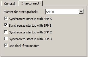
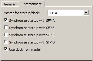
Interconnect
These options allow to synchronize multiple connected RT Boxes. Please also
read section “Time and Startup Synchronization” (on page 35).
Master for startup/clock Specifies on which SFP port the RT Box that is
acting as a master is connected. For the top level master or for standalone
boxes this option must be set to Self.
Synchronize startup with SFP x Enables startup synchronization on the
given SFP port. Boxes acting as a master must enable startup synchronization
on all ports to which a slave is connected. Boxes acting as a slave must enable
startup synchronization on the port to which the master is connected.
Use clock from master Enables simulation time step synchronization. The
SFP port to which the RT Box acting as master is connected must be specified
in option Master for startup/clock. No settings are necessary on the RT Box
acting as master.
CAN
These options allow to set up the CAN interfaces of the RT Box.
Enable CANx Enables or disables a CAN interface. If a CAN interface is
enabled and configured to use digital IO pins, these pins cannot be used for
other purposes (e.g. PWM generation or PWM capturing).
Baud rate The baud rate that is used on the connected CAN bus. All de-
vices on a CAN bus must be configured to use the same baud rate.
TX/RX pin Specifies which IOs to use for CAN communication. Each CAN
channel requires one input and one output pin. Select ’Internal CAN interface’
for the in-built CAN interface on the back of some RT Box models (see section
“CAN” (on page 20)).
326
Distributed Realtime Simula-
tion
A simulation model may be split up and run on multiple hardware nodes in
parallel. The advantages of this approach are:
• Increased number of I/Os
• Shorter simulation time steps
However, running different parts of a model on different hardware nodes also
poses some difficulties:
• The nodes may need to exchange information in every simulation step.
• The I/Os of the different nodes must be synchronized to guarantee consis-
tent electrical states.
• The simulation startup must be synchronized to guarantee consistent model
states.
This chapter describes how distributed realtime simulation can be faciliated
using multiple RT Boxes with minimal additional modifications to the simula-
tion model.
Model Setup for Distributed Realtime Simulation
Identifying Suitable Subsystems
As a first step the simulation model needs to be divided into suitable subsys-
tems for parallel simulation. Obvious candidates for independent subsystems
are isolated electrical circuits.
Another common solution is to separate circuit models at a capacitor or in-
ductor that can be replaced by a current source in one part of the model and6 Distributed Realtime Simulation
a voltage source in the other part. Both sources are controlled by respective
measurements in the other part of the model. This approach can often be ap-
plied to DC-link capacitors: Note that in an offline simulation a Delay block
Model with DC-link before split-up
z-1 A
V
Model with DC-link after split-up
is necessary in at least one direction of communication to prevent algebraic
loops.
Exchanging signals between two models
For physical distribution of the model onto different RT Boxes the code for
each part of the model must be generated separately. Therefore we need to
create a subsystem for each RT Box and place the corresponding part of the
model inside it.
34Time and Startup Synchronization
The signals between the subsystems are now replaced by SFP blocks. The
SFP ports establish a high-speed bidirectional serial communication link be-
tween two RT Boxes with a bandwith of 6.25 Gbps. To send signals from a
model over a SFP port use the SFP Out block (see page 69). To receive sig-
nals from an SFP port and use it in a model use the SFP In block (see page
68). The SFP communication introduces a latency of two simulation timesteps
SFP SFP
I A
In Out
port: SFP A port: SFP B
SFP SFP
V
Out In
port: SFP A port: SFP B
Rectifier Inverter
Model with communication over SFP
(i.e. model B processes the information from model A two timesteps after it
was processed by Model A). For offline simulations, these delays are modelled
internally in the SFP blocks, so no external delay block is necessary anymore.
In this example, SFP port A is used on the first box running the rectifier and
SFP port B is used on the second box running the inverter. This assumes that
a SFP cable connects port A on the first box with port B on the second box.
Signal relaying
Signals can be exchanged between any two boxes that have a direct physical
SFP connection. To exchange signals between boxes that are connected only
via other boxes, signal relaying must be manually provided on the boxes in
between:
In the case shown above the latency for a signal from Model A to Model C
(and vice versa) is four simulation steps.
Time and Startup Synchronization
In addition to simulation data exchange, the SFP connection allows synchro-
nizing the simulation time steps and the simulation startup between multiple
356 Distributed Realtime Simulation
SFP SFP SFP SFP
In Out In Out
port: SFP A Model B port: SFP B port: SFP A
Calculations for Model B port: SFP A
width: 1 Model C
width: 2
SFP SFP
SFP SFP In
In Out
Out
port: SFP A port: SFP A
Calculations for Model C port: SFP A port: SFP B width: 1
width: 2
Box A Box B Box C
Signal relaying
RT Boxes. Synchronization requires assigning “master” and “slave” roles to
SFP ports. For time step synchronization the clock signal from the master is
distributed to a number of slaves. All boxes with time step synchronization
enabled must use the same simulation step time.
For startup synchronization the master first waits for all registered slaves to
become available (and optionally synchronized with the master clock). Then
the master sends a start signal to all slaves simultaneously and also starts its
own simulation model.
The assignment of master and slave roles is done in the Interconnect set-
tings of the RT Box specific coder options. Please see section “RT Box Coder
Options” (on page 32) for further details.
Note that one RT Box can connect to a master on one SFP port and act as a
master for further RT Boxes connected to the other SFP ports. This results in
a tree-like structure where the clock signal is distributed from the tree root to
the subsequent levels. However, you should consider that clock jitter increases
with each level that is added to the tree. Configuration settings for four RT-
Boxes arranged in a tree with 3 levels are shown in the figure below.
Synchronized versus Unsynchronized Simulation
As stated above, the latency of a signal sent from one box to another box is
two simulation steps when the two boxes use synchronized simulation time
steps. This is the best solution for distributed simulations where the calcula-
tion time for each simulation step is roughly the same on all boxes.
Another common scenario is to use additional RT Boxes for I/O extension only.
To minimize I/O latency it may be advisable to not use simulation time step
synchronization. The RT Boxes running as I/O extender should run very sim-
ple models that only connect incoming SFP blocks to peripheral blocks and
36Time and Startup Synchronization
SFP SFP
Out Out
port: SFP A port: SFP B
Top-level master
Master & Slave Slave 1
SFP SFP
In In
port: SFP A port: SFP A
SFP
Out
port: SFP B
SFP
In
port: SFP A
Slave 2
Startup and time synchronization in a 3 level tree
vice versa. These models can typically be run with a step size of just 1 µs. In
this case, the SFP latency is reduced to the step size of the fast I/O extenders
376 Distributed Realtime Simulation
plus the time needed for SFP data transmission (typically well below 1 µs).
Another scenario where time step synchronization is not recommended is
when splitting the model into a fast part (e.g. for the electrical system) and
a slow part (e.g. the mechanical system). Both parts can then run on two RT
Boxes with different time steps.
387
Scripting
For automated test environments the RT Box can be controlled via external
scripts using an XML-RPC interface. XML-RPC is a lightweight protocol for
executing functions on a remote machine. The RT Box acts as an XML-RPC
server, which processes requests sent from scripts running on another com-
puter. Many scripting languages support XML-RPC out of the box, for exam-
ple Python or Ruby. For other scripting language, extensions for XML-RPC
support are available.
In the following examples, Python 2.x syntax and script excerpts are used.
Establishing an XML-RPC Connection to the RT Box
The RT Box listens to XML-RPC connections on TCP port 9998. The following
Python code initiates an XML-RPC connection to the RT Box:
import xmlrpclib
import socket
ip = socket.gethostbyname("examplebox.local")
server=xmlrpclib.Server("http://" + ip + ":9998/RPC2")
Note that the URL must end with "/RPC2", which is an XML-RPC convention.
Overview of XML-RPC Commands
Commands for PLECS start with rtbox followed by a dot. In Python they are
invoked on the server object, for example
server.rtbox.start()7 Scripting
Loading, starting and stopping a real-time simulation
The command
rtbox.load(binaryObject)
loads a new executable (ELF file) on the RT Box. The parameter binaryObject
must be a base64 encoded XML-RPC binary object. In Python, this object can
be created using the Binary object from xmlrpclib. The following code shows
how to read an ELF executable file and load it on the RT Box using Python:
with open("TestModel_codegen/TestModel.elf", "rb") as f:
server.rtbox.load(xmlrpclib.Binary(f.read()))
The command
rtbox.start()
starts the execution of the real-time simulation.
The command
rtbox.stop()
stops the execution of the real-time simulation.
Sending data to the real-time simulation
The command
rtbox.setProgrammableValue('componentPath', valueList)
sets the output of the Programmable Value block (see page 54) indicated by
componentPath. The parameter componentPath is the path of the block rel-
ative to the code generation subsystem.The parameter valueList must be an
XML-RPC array where the number of elements corresponds to the width of
the output signal. If the Programmable Value Block has an output signal with
a width of 1 a scalar value may be used as parameter. The example code be-
low changes an output of width 2 to the values 5 and 7:
rtbox.setProgrammableValue('Value1', [5.0, 7.0])
40Another example shows setting an output of width 1 to the value 7:
rtbox.setProgrammableValue('Value1',[7])
or
rtbox.setProgrammableValue('TestModel/Value1',7)
Getting data from the real-time simulation
The command
rtbox.getCaptureData('componentPath')
returns the last filled data buffer from the Data Capture block (see page 49)
indicated by componentPath. The parameter componentPath is the path of the
block relative to the code generation subsystem.The returned value is a struct
with the following fields:
data
The data as a two-dimensional array. The inner dimension corresponds
to the width of the input signal, the outer dimension corresponds to the
number of samples.
triggerCount
Specifies how many times the sample buffer has been filled.
sampleTime
Specifies the time between two samples, in seconds.
The command
rtbox.getCaptureTriggerCount('componentPath')
returns how many times the sample buffer of the Data Capture block (see
page 49) indicated by componentPath has been filled. The parameter compo-
nentPath is the path of the block relative to the code generation subsystem.
The command
rtbox.getDataCaptureBlocks()
returns a list of all Data Capture blocks in the current model, with path.
The command
417 Scripting
rtbox.getProgrammableValueBlocks()
returns a list of all Programmable Value blocks in the current model, with
path.
Example Script
This Python script loads a new executable on the RT Box and starts it. It sets
a value and reads some values back from the model after the correspond-
ing data block has captured sufficient data. The Data Capture block “Cap-
ture1” and the Programmable Value block “Value1” must be placed in the root
schematic of the model. Finally, the real-time simulation is stopped.
import xmlrpclib
# Python 3:
# import xmlrpc.client
import socket
import time
import random
ip = socket.gethostbyname("examplebox.local")
server=xmlrpclib.Server("http://" + ip + ":9998/RPC2")
# Python 3:
# server=xmlrpc.client.ServerProxy("http://" + ip +
# ":9998/RPC2")
with open("TestModel_codegen/TestModel.elf", "rb") as f:
print("Uploading executable")
server.rtbox.load(xmlrpclib.Binary(f.read()))
f.closed
print("Starting executable")
server.rtbox.start()
print("Simulation running")
val = random.random()
print("Setting value %.7f" % val)
server.rtbox.setProgrammableValue('Value1', [val])
while server.rtbox.getCaptureTriggerCount('Capture1') == 0:
print("Waiting for data")
time.sleep(1)
data = server.rtbox.getCaptureData('Capture1')
print("Got value %.7f" % data['data'][0][0])
print("Stopping executable")
server.rtbox.stop()
428 RT Box Target Support Library Component Reference This chapter lists the contents of the RT Box Target Support library in alpha- betical order.
8    RT Box Target Support Library Component Reference

     Analog In

     Purpose                Output the measured voltage at an analog input channel.

     Library                PLECS RT Box

     Description            The output signal is scalable and can be used with an offset. The output sig-
                            nal is calculated as input*Scale+Offset.


     Parameters             Analog input channel(s)
                              Index of the analog input channel. For vectorized input signals a vector of
                              input channel indices must be specified.
                            Scale
                               A scale factor for the input signal.
                            Offset
                               An offset for the scaled input signal.

44
Analog Out
Analog Out
Purpose Set the output voltage of an analog output channel.
Library PLECS RT Box
Description The output voltage is scalable and can be used with an offset. The output volt-
age is calculated as input*Scale+Offset. Further, an output voltage limitation
can be set.
Parameters Analog output channel(s)
Index of the analog output channel. For vectorized output signals a vector
of output channel indices must be specified.
Scale
A scale factor for the output signal.
Offset
An offset for the scaled output signal.
Minimum output voltage
The lowest value that the output voltage can reach.
Maximum output voltage
The highest value that the output voltage can reach.
458 RT Box Target Support Library Component Reference
CAN Receive
Purpose Receives CAN messages.
Library PLECS RT Box
Description The block initiates the reception of CAN messages with the given ID on the
given CAN interface. On reception of a CAN message the data is made avail-
able on the block output d as a vectorized signal consisting of 8 bytes. The
output v is 1 in each simulation step where new data is received, 0 otherwise.
The data at block output d always has a width of 8 bytes regardless of the
length of the received CAN message.
Parameters CAN interface
The CAN interface to use. The selected CAN interface must be configured
in the RT Box Coder Options Dialog (see section “CAN” on page 32).
CAN ID source
Selects whether the CAN ID is specified as a parameter or is supplied as
an input signal.
CAN ID
The CAN identifier for which this block receives CAN messages. The CAN
ID can be supplied as either a 11 bit value (vor CAN 2.0A) or 29 bit value
(for CAN 2.0B).
Frame format
Specifies the frame format that is used when filtering for matching CAN
messages. Possible values are:
• Base for CAN 2.0A messages with an 11 bit identifier
• Extended for CAN 2.0B messages with an 29 bit identifier
• Auto uses the Base format if the specified CAN ID is smaller than 2047.
Otherwise, the Extended format is used.
Offline simulation
Enables or disables data injection in an offline simulation. If set to en-
abled, terminals are added to the subsystem for which code is generated.
In an offline simulation the data which is to be received by the CAN Re-
ceive block can be injected into these terminals. The block must be placed
in the root schematic of the subsystem for which code is generated. If set
to disabled, no such terminals will be added and the block can be used at
any subsystem level.
46CAN Transmit
CAN Transmit
Purpose Transmits CAN messages.
Library PLECS RT Box
Description The CAN Transmit block sends out data on a CAN bus. The data to send
must be provided on the block input d as a vectorized signal with data type
uint8. The length of the transmitted CAN message is determined by the
width of the input signal (1 to 8 bytes).
Messages are either sent regularly with a fixed sample time or on demand
when the trigger input changes. When configured for triggered execution, mes-
sages are sent when the trigger signal changes in the manner specified by the
Trigger type parameter:
rising
Data is sent when the trigger signal changes from 0 to a non-zero value.
falling
Data is sent when the trigger signal changes from a non-zero value to 0.
either
Data is sent when the trigger signal changes from 0 to a non-zero value or
vice versa.
Parameters CAN interface
The CAN interface to use. The selected CAN interface must be configured
in the RT Box Coder Options Dialog (see section “CAN” on page 32).
CAN ID source
Selects whether the CAN ID is specified as a parameter or is supplied as
an input signal.
CAN ID
The CAN identifier that is used for CAN messages sent by this block. The
CAN ID can be supplied as either an 11 bit value (for CAN 2.0A compli-
ance) or 29 bit value (for CAN 2.0B compliance).
Execution
Selects between regular and triggered execution.
Sample time
The time period for regular packet transmission (for regular execution
only).
478 RT Box Target Support Library Component Reference
Trigger type
The direction of the edges of the trigger signal upon which the data is
sent, as described above (for triggered execution only).
Offline simulation
Enables or disables data inspection in an offline simulation. If set to en-
abled, terminals are added to the subsystem for which code is generated.
In an offline simulation the data sent to the CAN Transmit block is avail-
able at these terminals. The block must be placed in the root schematic
of the subsystem for which code is generated. If set to disabled, no such
terminals will be added and the block can be used at any subsystem level.
48Data Capture
Data Capture
Purpose Capture data to be transferred via XML-RPC.
Library PLECS RT Box
Description The Data Capture block captures simulation data from real-time simulations
that are controlled by an external script. The captured data can be queried via
the XML-RPC interface of the RT Box.
All captured data is written into an internal buffer first. The size of the buffer
is controlled by the parameter “Number of samples”. Once the buffer is full,
the data can be read via XML-RPC. See “Getting data from the real-time sim-
ulation” on page 41 for a description of XML-RPC commands to access the
Data Capture block.
The start of data capturing can be controlled with an optional trigger signal.
Parameters Number of samples
The number of samples that are captured before data is accessible via
XML-RPC.
Trigger type
Specifies the edge of the trigger signal that starts data capturing. If set to
“continuous” the trigger input is ignored.
Trigger level
Defines the value that the trigger signal must reach to become active.
498 RT Box Target Support Library Component Reference
Digital In
Purpose Read a digital input.
Library PLECS RT Box
Description The output signal is 1 if the input voltage is higher than 2 Volts and 0 if it is
lower than 0.8 Volts. For other input voltages the output signal is undefined.
Parameters Digital input channel(s)
Index of the digital input channel. For vectorized input signals a vector of
input channel indices must be specified.
Input characteristic
Specifies whether an internal pull-up or pull-down resistor is connected to
the digital input.
50Digital Out
Digital Out
Purpose Set a digital output.
Library PLECS RT Box
Description The output is set low if the input signal is zero, it is set high for all other val-
ues. During an offline simulation the block behaves like a simple feedthrough.
Parameters Digital output channel(s)
Index of the digital output channel. For vectorized output signals a vector
of output channel indices must be specified.
518 RT Box Target Support Library Component Reference
Incremental Encoder
Purpose Generate quadrature encoder signals on digital outputs.
Library PLECS RT Box
Description The Incremental Encoder takes a rotational angle θ as input and generates
quadrature encoder signals with an optional index pulse on selected digital
outputs of the RT Box. During an offline simulation the pulses are available
on the outputs.
Parameters
General
Encoder module
Specifies used encoder module.
Line pairs
Defines the amount of pairs of black and white lines and therefore the en-
coder resolution. For every line pair, 4 state transitions at A, B per revolu-
tion can be seen. The index pulse at I is set once per revolution when the
angle crosses 0.
Coding in forward direction
Defines the A,B state sequence in forward direction.
Output when θ=0
Specifies the value of signals A and B when the input angle θ is zero and
an index pulse is generated.
Offline implementation
With the setting Continuous θ and ω are made available in for offline
simulation. With the setting Quadrature Encoded the quadrature sig-
nals A, B and I are made available as a vectorized signal.
Output
Digital encoder output [A] or [A, /A]
Indices of the digital outputs for signal A. If the signal is differential the
value must be a vector with two elements where the second element spec-
ifies the output for the differential signal Ā. For single-ended outputs the
value must be a scalar or a vector with one element.
52Incremental Encoder
Digital encoder output [B] or [B, /B]
Indices of the digital outputs for signal B. If the signal is differential the
value must be a vector with two elements where the second element spec-
ifies the output for the differential signal B̄. For single-ended outputs the
value must be a scalar or a vector with one element.
Digital index output [I] or [I, /I]
Indices of the digital outputs for index signal I. If the signal is differential
the value must be a vector with two elements where the second element
¯ For single-ended outputs
specifies the output for the differential signal I.
the value must be a scalar or a vector with one element. If the index sig-
nal output is not needed this parameter can be left empty.
Inputs θ
The rotational angle or rotor position.
53You can also read