Operating Instructions Feeding station Intec MAC
←
→
Page content transcription
If your browser does not render page correctly, please read the page content below

Operating Instructions
   Feeding station
     Intec MAC

      Operating Instructions for Intec MAC 1.00 En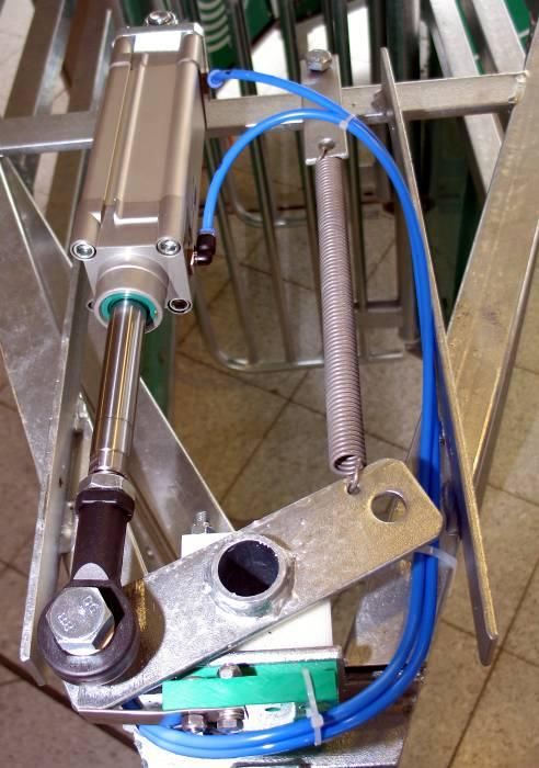
List of contents
IMPORTANCE OF THE OPERATING AND ASSEMBLY INSTRUCTIONS            6

GENERAL SAFETY INSTRUCTIONS                                      7

  DUTY OF CARE OF OPERATING COMPANY                              7
  EXPLANATION OF SAFETY SYMBOLS                                  7
  BASIC SAFETY MEASURES                                          8
    Maintenance and service                                     10
    Carrying out work on electrical systems                     11
    Carrying out work on the pneumatic system                   12
  OBSERVE THE ENVIRONMENTAL INSTRUCTIONS                        12
  MODIFICATIONS TO THE MACHINE                                  13
  REQUIREMENTS PLACED ON THE OPERATING STAFF                    13
  SPECIAL DANGERS                                               13
    Dangers due to noise                                        13
    Risks due to consumables and other substances               13

PRODUCT DESCRIPTION                                             14

  INTENDED USE                                                  14
  USE OTHER THAN THAT INTENDED                                  14

CONSTRUCTION AND OPERATION                                      15

  GENERAL DESCRIPTION                                           15
  FUNCTIONAL DESCRIPTION                                        16
  CONSTRUCTION                                                  17
   Entrance door                                                17
   Energy supply and feeder                                     19
   Feed reservoir and water connection                          20
   Feed box                                                     21
   Dispenser and trough flap                                    22
   EXIT                                                         23
   MAC Server                                                   24

OPERATION                                                       26

  CONTROL PANEL – RIGHT-HAND SIDE                               27
   Operating modes of the Intec MAC                             28
   Operating modes of the entrance door                         29
   The trough flap operating modes                              30
   The selection gate operating modes                           31
   Manual actions                                               32
  CONTROL PANEL – LEFT-HAND SIDE                                33
  CONFIGURATION AND SERVICE SETTINGS                            38

                             INTEC MAC OPERATING INSTRUCTIONS        PAGE 2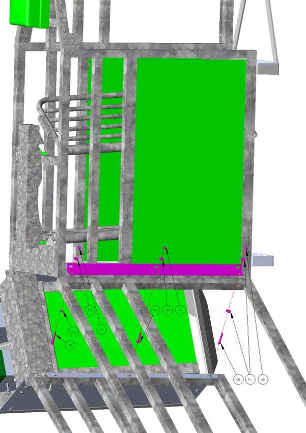
INTEC MAC

    Feed calibration                                                   39
    Feed amount volume in the feed pipe                                39
    Power supply check                                                 39
    Antenna tuning                                                     40
    Ignore entrance door sensor                                        40
    Configure station                                                  40
  DESCRIPTION OF THE STEPS WHEN THE INTEC MAC PROGRAM STARTS           42
    Step 5                                                             42
    Step 8                                                             42
    Step 11                                                            42
    Step 14                                                            42
    Step 15                                                            42
    Step 17                                                            42
    Step 20                                                            42

OPTIONS                                                                43

  SELECTION                                                            43
    Selection confirmation menu (if configured)                        43
  SUBSTANCE DISPENSER                                                  46
  COLOR MARKING                                                        47
  CLAW SPRAY UNIT                                                      48
  REGUMATE                                                             49
    Regumate counter menu (Regumate addition, if configured)           50

TECHNICAL SPECIFICATIONS                                               51

GENERAL SAFETY INSTRUCTIONS                                            51

MODIFICATIONS TO THE MACHINE                                           51

REQUIREMENTS PLACED ON THE OPERATING STAFF                             51

SPECIAL RISKS                                                          51

  TRANSPORTING MACHINE PARTS - SAFETY INSTRUCTIONS                     52
    Delivery                                                           53
  REQUIREMENTS AS REGARDS STORING SPARE PARTS                          54
  DIMENSIONS AND WEIGHT                                                55

ASSEMBLY                                                               55

  GENERAL                                                              55
  ASSEMBLY AND INSTALLATION                                            56

SAFETY FEATURES                                                        56

                               INTEC MAC OPERATING INSTRUCTIONS               PAGE 3
GENERAL INFORMATION ON COMMISSIONING AND/OR RECOMMISSIONING                        57

    De-commissioning                                                               57
    Basic adjustments                                                              57

COMMISSIONING THE MAC SYSTEM                                                       58

  PRECONDITIONS FOR COMMISSIONING                                                  58
  COMMISSIONING THE DEVICES                                                        58
  NETWORK CONNECTION OF THE DESKTOP PC                                             59
  DETERMINING THE NETWORK ADDRESS                                                  59
  THE CONFIGURATION MENU                                                           60
    The user data                                                                  60
    Search devices                                                                 60
    The device list                                                                61
    Saving the configuration                                                       62

TROUBLESHOOTING                                                                    63

  ERROR MESSAGES                                                                   63

MAINTENANCE AND SERVICE                                                            66

APPENDIX 1 - BARN LAYOUT                                                           68

    Example configuration for right-hand and left-hand versions of the Intec MAC   68

APPENDIX 2 - ASSEMBLY INSTRUCTIONS                                                 69

  ELEMENTS OF THE INTEC MAC SYSTEM                                                 69
  EXAMPLE DIAGRAM FOR 115/230V WIRING OF THE INTEC MAC SYSTEM                      70
  EXAMPLE DIAGRAM FOR ETHERNET WIRING OF THE INTEC MAC SYSTEM                      71
  GENERAL INSTRUCTIONS ON MECHANICAL ASSEMBLY OF THE INTEC MAC                     72
  ELECTRICAL AND PNEUMATIC ASSEMBLY OF THE INTEC MAC                               77
    Overview of junction box                                                       77
    Elements in the junction box                                                   78
    Configuration of the main connection hub                                       79
    Connection configuration of the extension connection hub (6-fold)              80
    Contact configuration of the M12 sockets and plugs                             81
  FEEDER CONTROL CONNECTION                                                        82
  INTEC MAC CONNECTION                                                             83
  METRACONTROLLER CONNECTION                                                       84
  CONNECTION OF FEEDER CONTROL CONTACT FOR EXTERNAL CONTROL                        85
  MOTOR SWITCH CONNECTION                                                          86
  METRA CONTROLLER CONNECTION CABLE TO THE MOTOR SWITCH                            87
  QUICKON ONE PLUG CONNECTION                                                      88

                               INTEC MAC OPERATING INSTRUCTIONS                         PAGE 4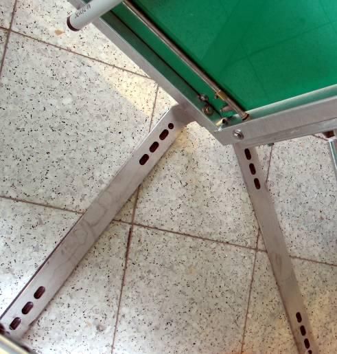
INTEC MAC

Y-CABLE CONNECTION                                           88

                     INTEC MAC OPERATING INSTRUCTIONS               PAGE 5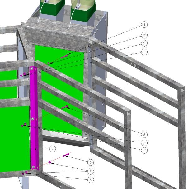
Importance of the Operating and Assembly Instructions
The Operating Instructions form is an integral part of the Intec MAC and:
they must be kept within immediate reach at all times, i.e. until the Intec MAC is
disposed of.
they must be passed on when selling, transferring or lending the Intec MAC.
We welcome all suggestions and feedback from you communicated orally or in writing. This
helps us make these Operating Instructions more user friendly, in line with your wishes and
requirements.
Since the Intec MAC may imply residual risks for people and property that cannot be
avoided, every person involved in transporting, installing, operating, maintaining and
repairing the Intec MAC must be properly instructed and must familiarize themselves with the
possible risks by carefully reading, understanding and observing the Operating Instructions
and specifically the safety instructions.
Insufficient knowledge of the Operating Instructions invalidates any and all rights to hold the
manufacturer liable. We recommend having personnel confirm in writing that they have been
thoroughly instructed.
Version 1.00 en
The manufacturer reserves the right to make changes to your product in keeping with the latest
technical developments. These individual changes are not necessarily always documented.
These Operating Instructions and the information contained in them have been compiled with all
due care. However, the manufacturer does not assume any liability for printing errors or other
errors and any damage or loss resulting from such errors.
The brand names and product names mentioned in this document are trademarks or registered
trademarks of their respective holders.
Our contact details: PigTek Europe GmbH
Industriestraße 7
48465 Schüttorf, Germany
Phone : +49 (0)59 23-96 47-0
Fax: +49 (0)59 23-96 47-47
Internet: www.pigtek.eu
INTEC MAC OPERATING INSTRUCTIONS PAGE 6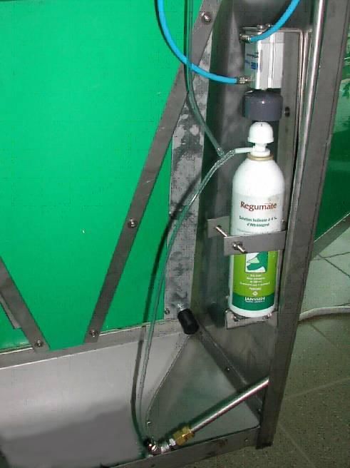
INTEC MAC

General safety instructions
Duty of care of operating company
The machine was constructed and built duly considering a risk analysis and following a
careful selection of the standards to be complied with and the further technical specifications.
As a result, it complies with the latest state of technology and guarantees optimum safety.
However, this safety can only be achieved in daily operating practice if all measures required
to such effect have been taken. It is the operating company's duty of care to plan these
measures and check their implementation.
The operating company must make sure in particular that
        the machine is only used according to its intended use (see chapter 5, Product
        description)
        the machine is only operated if it is in a technically perfect state and is functioning
        properly; the safety features must specifically be checked for their proper functioning
        on a regular basis
        the required personal safety equipment for the operating, maintenance and repair
        staff is available and is used
        the Operating Instructions are always available in a legible state and in their entirety
        at the machine's location of use
        the machine is only operated, maintained and repaired by sufficiently qualified and
        authorized staff
        such staff are regularly instructed on all relevant working safety and environmental
        issues and in particular know the Operating Instructions and the safety instructions
        contained therein
        all safety and warning instruction notices on the machine are always in place and
        legible.

Explanation of safety symbols
The following Operating Instructions contain specific safety instructions pointing out any
unavoidable residual risks that are present while the machine is being operated. These
residual risks concern dangers for
        People
        Animals
        The machine
        The environment
The symbols used in the Operating Instructions are mainly intended to alert you to the
safety instructions!

                  This symbol indicates that there is mainly a risk of danger to people.
                  (danger of fatal accidents, danger of injuries)
                  Any failure to observe these instructions may result in serious injury
                  or death.
    Danger!

                                  INTEC MAC OPERATING INSTRUCTIONS                                 PAGE 7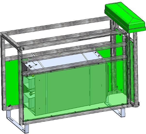
This symbol indicates that there is mainly a risk of danger to the
                 machine, equipment and the environment.

                 Any failure to observe these instructions may result in faults and
                 damage to the machine, as well as damage to property and the
   Caution!      environment.

The main objective of the safety instructions is to prevent personal injury.
        If a safety instruction is preceded by a warning triangle with the word "Danger”
        under it, dangers to the machine, materials and the environment are not excluded.
        However, if a safety instruction is preceded by a warning triangle with the word
        "Caution” under it, dangers to people are not immediately expected.

Also remember that a safety symbol can never replace the text of a safety instruction: you
must always read the complete text of a safety instruction!

                  This symbol does not mark any safety instructions, but installation or
                  other useful information.

Basic safety measures
These Operating Instructions contain all the essential instructions to be able to use the
machines safely.
These Operating Instructions must be stored near the machine. It must be guaranteed that
all personnel who carry out activities on the machine can refer to the Operating Instructions
at all times. In addition to these Operating Instructions, the company must also make
operating instructions available pursuant to the [German] Act on safety at work and the
Decree on using tools and equipment.
All signs bearing safety and operating instructions on the machine must always be kept in a
properly legible condition. Immediately replace any damaged or illegible signs.

                 The machine must only be operated by properly trained and authorized
                 personnel who are familiar with these Operating Instructions and can work
                 in keeping with them!
                 Make sure that you are sufficiently familiar with
                     the operating and control elements of the machine
                     the configuration of the machine
                    the operation of the machine
                    the direct vicinity of the machine
                    the safety features on the machine
                    the emergency measures

                 Before switching on the machine, check and make sure that

                                 INTEC MAC OPERATING INSTRUCTIONS                               PAGE 8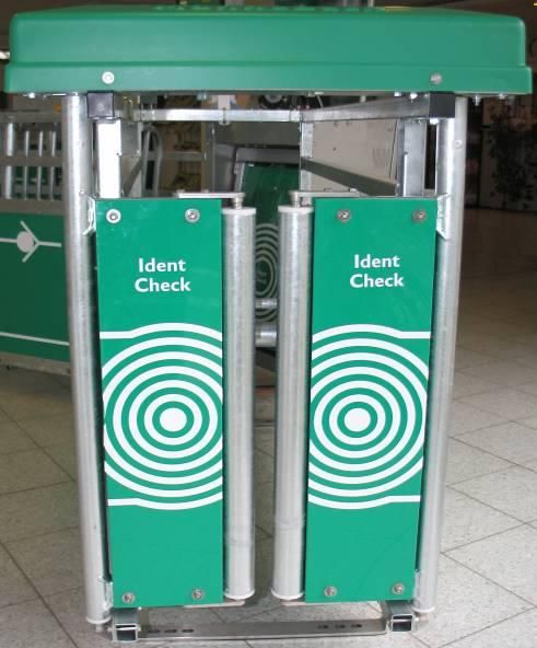
INTEC MAC

          only authorized personnel are in the working range of the
          machine!
          nobody can be injured by the machine while it is starting up!
Danger!   the machine has been checked for visual damage and is only
          operated in a technically perfect condition! Immediately report
          any defects found to your superior!
          any material not required for feeding has been removed from the
          working range of the machine!
          all safety features work perfectly!
          the machine is only started from the designated workstation.
          no safety features are removed or deactivated while the machine
          is running.
          no unauthorized personnel are in the working range of the
          machine!

                     INTEC MAC OPERATING INSTRUCTIONS                       PAGE 9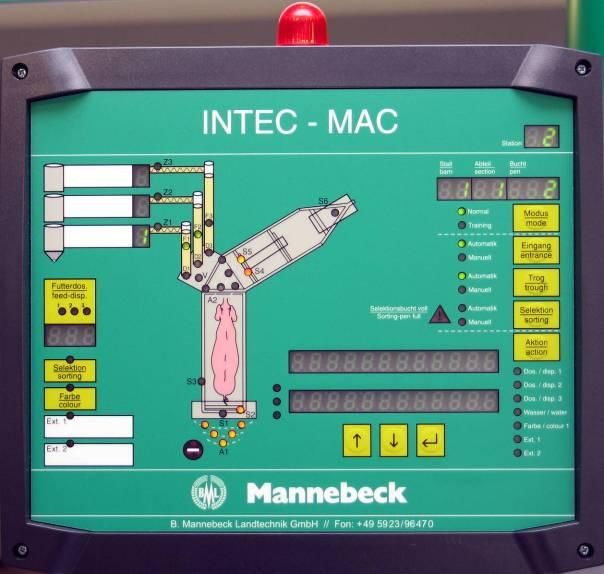
After switching off the machine, the operating staff must wait for all
                moving parts to have stopped moving and for the operating
                indicators to have extinguished before leaving the machine
                unsupervized.
   Danger!      Perform the following checks at least once a day:
                       check the exterior of the machine for visible damage
                       check the functioning of all safety features

Maintenance and service
Observe the inspection and maintenance intervals laid down in the Operating Instructions!
Observe the Maintenance and Repair Instructions for the individual components in these
Operating Instructions!
Immediately replace any machine parts that are not in perfect condition!
Only use original spare parts!

                Before carrying out maintenance or repair work:
                      secure the working range of the machine so that unauthorized
                      personnel cannot enter it!
                      Apply or put up a warning sign to alert people to the
   Danger!
                      maintenance or repair activities!
                      switch off the main switch to interrupt the power supply and
                      padlock it! The key to this lock must be held by the person
                      who is carrying out the maintenance or repair work!
                      Make sure that any parts of the system which have been
                      depressurized cannot be unexpectedly switched on again!
                      Use suitable and technically perfect lifting or hoisting devices
                      and sling gear to replace heavy machine parts!
                      Before carrying out any maintenance or repair work, make
                      sure that any parts of the machine you might touch have
                      cooled down to room temperature!
                      Dispose of any environmentally harmful lubricants,
                      refrigerants or detergents in keeping with applicable
                      regulations!

                                INTEC MAC OPERATING INSTRUCTIONS                            PAGE 10
INTEC MAC
Pay attention to the following after completing the maintenance
activities and before starting the machine:
Double-check that all screwed connections that were loosened
are tight!
Danger!
Check that all safety features and covers that were removed
have been properly installed again!
Make sure that all tools, materials and other equipment used
have been removed from the work area!
Clean the work area and remove any liquids or other
substances that have leaked out or escaped!
Make sure that all safety features on the machine work
properly again!
Carrying out work on electrical systems
Repairs to electrical systems on the machine must only be
carried out by professional electricians!
Regularly check all electrical systems!
Danger! Repair loose connections!
Immediately replace any damaged leads/cables!
Keep the control cabinet closed at all times! Only authorized
personnel who have the right key/tool are allowed to access the
control cabinet!
Never spray clean switch cabinets and other electrical
equipment housings using water hoses!
Whenever work is carried out on live machine parts or circuits a
second person must be present to switch off the main switch in
case of an emergency!
INTEC MAC OPERATING INSTRUCTIONS PAGE 11Carrying out work on the pneumatic system
Maintenance and repair work on the pneumatic system must
only be carried out by specifically trained staff!
Depressurise the pneumatic system of the machine before
carrying out any maintenance or repair activities!
Danger!
Regularly replace hoses as part of your preventative
maintenance routine, even if they do not appear to be damaged!
(Observe the manufacturer's instructions!)
Before re-commissioning after maintenance or repair work
check that all screwed connections which were undone are
tight again
make sure that reservoir covers, screens or filters which were
removed have been installed again
After completing maintenance or repair activities and before restarting
the feeding operation make sure that
all materials, tools and other gear needed for the maintenance
or repair activities have been removed from the working range
of the system
any liquids that have leaked out have been removed
all safety features on the system work perfectly!
Observe the environmental instructions
Observe the statutory requirements on preventing waste and on
proper recycling/disposal whenever work is carried out on or with the
machine
Caution!
Especially when installation, repair and/or maintenance activities are
carried out, make sure that substances that might pollute the water
such as
greases and lubrication oils
solvent-containing cleaning fluids
do not contaminate the soil or end up in the sewage system!
These substances must be stored, transported, collected and
disposed of in suitable containers!
INTEC MAC OPERATING INSTRUCTIONS PAGE 12INTEC MAC
Modifications to the machine
For reasons of safety, unauthorized modifications to the machine are strictly prohibited! This
also applies to welding work on load-bearing parts.
All changes and modifications planned must be approved in writing by PigTek Europe
GmbH.
Immediately replace any machine parts that are not in a defect-free condition.
Only use original spare parts / original wearing parts / original accessories - these parts were
designed and constructed specifically for the machine in question. If parts are purchased
from third parties there is no guarantee that they have been constructed and produced to
meet the relevant stress/load and safety requirements.
The use of parts and special equipment not planned by PigTek Europe GmbH on the
machine is explicitly not allowed.
Requirements placed on the operating staff
The machine must only be operated by properly trained, instructed and authorized staff.
Such personnel must be familiar with and observe the Operating Instructions.
Operating staff still in training may initially only work on the machine if supervized by an
experienced person. When training has been completed successfully this must be confirmed
in writing.
In principle, all control and safety features must only be operated by properly instructed staff.
All personnel carrying out activities on the machine must read the Operating Instructions and
must sign to confirm that they have understood them.
Special dangers
Dangers due to noise
The continuous sound pressure level for the operating staff is < 85 dB(A).
Depending on the local conditions, higher sound pressure levels may occur which may lead
to deafness, loss of equilibrium or reduced alertness. In such cases, suitable personal safety
equipment must be made available to the operating staff.
Observe the noise instructions in the operating instructions for your place of work and use
the prescribed personal safety equipment.
Risks due to consumables and other substances
The substances used to operate and clean the machine such as oils, solvents and
detergents must be handled and disposed of properly. Observe the instructions on the
relevant reservoirs and, if relevant, the producer's material safety data sheets.
INTEC MAC OPERATING INSTRUCTIONS PAGE 13Product description
Intended use
The Intec MAC has been built in accordance with the latest technological developments and
recognized technical safety rules. Its use may cause risks of physical or lethal injury to the
user or third parties and/or damage to the machine and other property.
The Intec MAC must only be used if it is in a technically perfect condition and in line with its
intended use, duly observing all safety risks and in accordance with the Operating
Instructions! Immediately remedy any malfunctions which may affect safety!
The Intec MAC
has been developed specifically for the feeding of pigs.
must be installed and connected in keeping with the Assembly Instructions. Only then
is safe operation possible and only then will the system work without any problems.
must be operated in keeping with the ambient conditions laid down, i.e. in a
temperature range of 10 – 40°C.
Any use deviating from or exceeding this is considered to be improper. The manufacturer is
not liable for any damage resulting from such non-intended use;
Observing the Operating Instructions, specifically the safety instructions, and the inspection
and maintenance specifications is also an integral part of the intended use.
Use other than that intended
Any use other than that specified above is forbidden. Use other than that intended may pose
risks. Such use other than that intended includes:
the feeding of living beings other than pigs.
operation under ambient conditions other than those agreed.
The safe operation of the machine is not guaranteed if the Intec
MAC is not used in accordance with this intended use.
PigTek Europe GmbH is not responsible for any personal injuries
Danger! or material damage or loss resulting from other than intended use.
Please consult PigTek Europe GmbH if you have any questions or doubts as to
the use of the Intec MAC.
INTEC MAC OPERATING INSTRUCTIONS PAGE 14INTEC MAC
Construction and operation
General description
The specific characteristics of the Intec MAC which have resulted from many years of
development and construction experience are:
Optimum reliability and optimum possibilities for monitoring and maintenance by the
personnel.
Rapid and easy replacement of wearing parts.
Amply spaced access openings enable easy, thorough and rapid cleaning.
Minimum space requirement due to compact design.
Long service life thanks to amply dimensioned construction elements and [bearings].
Optimum protection against corrosion.
INTEC MAC OPERATING INSTRUCTIONS PAGE 15Functional description
The Intec MAC has been designed for automatic sow feeding. The integrated feed
management system enables individual feed amounts to be dispensed to every single
animal. The individual animals are identified by means of passive ear tag transponders.
Every feeding station can be operated locally from a permanently installed control panel. The
network connection enables several feeding stations to be connected to and
programmed/operated from one central PC.
Optional accessories are available to expand the machine's functionality (e.g. selection gate
at the exit, color marking, claw care, automated addition of feed additives)
6
5
1 2 3 4
Figure 1: Intec MAC
1 Entrance door
2 Entrance
3 Exit
4 Selection gate
5 Feed box
6 Intec MAC box
INTEC MAC OPERATING INSTRUCTIONS PAGE 16INTEC MAC
Construction
Entrance door
(Figure 2 - 5)
The entrance door is secured to the frame (1) of the station. It has two door leaves (2) that
swing out and that have freely rotating rollers (3) on the inside.
The pneumatic drive (4) with the turning bar (5), the locking mechanism (6) and the locking
sensor (7) have been installed at the top and are protected against direct access on all sides.
The green safety cover (8) has been screwed onto the frame for safety reasons. All leads
and circuits (9) have been laid in the upper frame and are protected.
In normal operating mode the door is opened whenever the transponder of a sow entitled to
feed is recognized by the antenna. The door can also be operated manually from the Intec
MAC Box (see the chapter on Operation)
8
1
2
3
Figure 2: Entrance door
INTEC MAC OPERATING INSTRUCTIONS PAGE 176
9
Figure 3: Entrance door, closed
4
5
Figure 4: Entrance door, open
7
Figure 5: Entrance door, lock
INTEC MAC OPERATING INSTRUCTIONS PAGE 18INTEC MAC
Energy supply and feeder
(Figure 6)
The feeding station is powered by low voltage (24V DC) from a decentralized power supply
unit at the station.
A central compressed air connection supplies compressed air to the pneumatic system of the
station.
A network cable connects the station to the MAC Server and to other stations.
The Intec MAC feeding station can be configured with any kind of feeder. The example in the
figure shows a system in which a tube system (1) transports the feed into the feed
reservoir(s) (2) of the station.
1
2
Figure 6: Feeder
INTEC MAC OPERATING INSTRUCTIONS PAGE 19Feed reservoir and water connection
(Figure 7)
A request to top up the reservoir (1) is generated by a feed sensor (2) which can be installed
at any random location in the reservoir wall. If the level falls to below the sensor position it
will report "no feed" to the control system and the station will switch the output for the
relevant feeder (3) accordingly.
Any random reserve amount of feed can be programmed to ensure that there is sufficient
time to top up the feed reservoir without feeding being interrupted.
The water supply connection (4) with the stop valve and the water valve is located at the top
of the feed box where it is easily accessible.
3
1
2
4
Figure 7: Feed reservoir
INTEC MAC OPERATING INSTRUCTIONS PAGE 20INTEC MAC
Feed box
(Figure 8)
The feed box is located in the centre of the station.
The rear wall (1) can easily be removed for maintenance and cleaning.
The feed box contains one or two dispenser(s) (2), the swivelling trough flap with the
integrated antenna for transponder identification (3), the trough (4), the water valve, and the
junction box (5) with the compressed air control valve block.
2
1
5
3
4
Figure 8: CAD view of feed box
INTEC MAC OPERATING INSTRUCTIONS PAGE 21Dispenser and trough flap
(Figure 9)
The dispenser (1) is accessible when the rear wall has been removed. It consists of a sheet-
metal funnel with a rotating dispensing roller at its lower end. Its drive consists of a
pneumatic cylinder (2), every stroke of which turns a star-shaped wheel (3) one position
further. The required amount of feed to be dispensed is controlled by the number of strokes
and falls into the trough (4).
One or two dispensers can be installed in the feed box.
The trough flap (6) is swivelled open and closed by means of another pneumatic cylinder (7).
It is installed on a side bracket in the feed box and connected to the rotary shaft of the flap by
means of a swiveling level.
1
2
3
6
7
4
Figure 9: Feed box inside, without safety features
INTEC MAC OPERATING INSTRUCTIONS PAGE 22INTEC MAC
EXIT
(Figure 10)
The exit contains two doors that close automatically, one after the other. To ensure that no
animals enter the station in a reverse direction to the walking direction, the doors are
interlocked mechanically (1). Door 1 (2) must be opened before door 2 (3) can be pushed
open.
The exit doors are monitored by sensors. They check that the exits are opened and closed
again in the right order to make sure that the animals have properly left the station or have
returned to the station.
1
2
3
Figure 10: Exit
INTEC MAC OPERATING INSTRUCTIONS PAGE 23MAC Server
(Figures 11 - 13)
The MAC Server is necessary in order to operate the Intec MAC feeding station. The server
housing contains the following components:
Power supply unit (1)
USB network adapter (2)
Ethernet switch (3)
UPS - uninterruptible power supply (4)
UPS main switch with indicator (5)
Server on/off switch (6)
Figure 11: Server housing
INTEC MAC OPERATING INSTRUCTIONS PAGE 24INTEC MAC
Figure 12: Server with integrated components
Figure 13: Server on/off switch
INTEC MAC OPERATING INSTRUCTIONS PAGE 25Operation
(Figure 14)
A controller, the Intec MAC Box, is installed at every feeding station. It consists of a water-
resistant, impact-proof front with input buttons, indicators and text displays.
A schematic view of the feeding station with multi-colored indicators shows the status of the
integrated sensors connected in the feeding station.
Feeding station failures are indicated by means of a warning lamp (see arrow) screwed onto
the housing in a clearly visible position. Error codes are displayed to identify the causes of
the relevant failures.
The Configbox is mounted on the rear and is connected to the control panel by means of a
plug-and-socket connection. All basic data, e.g. the feeding station configuration with all
accessories, is permanently factory-programmed in this box. This enables the Intec MAC
Box to be replaced fast, without further programming.
Figure 14: Intec MAC Box sensors and function statuses
INTEC MAC OPERATING INSTRUCTIONS PAGE 26INTEC MAC
Control panel – right-hand side
(Figure 15)
The upper right-hand side section of the control panel contains 3 displays (1) with information
about the location of the feeding station, which is laid down in the configuration. These
displays enable easy identification of the relevant feeding station, especially when the
system comprises several feeding stations which are programmed via the PC program.
The same applies to switching over between automatic and manual mode for the entrance,
trough and selection or 'sorting' functions (3). The red warning lamp on the box is lit
whenever the "normal" or "automatic" modes have not been selected for these functions.
An additional warning lamp (4) is activated when the maximum number of animals for the
selection pen has been reached in sorting mode.
The currently active status is indicated by the LEDs on the left of the buttons.
The "action" button enables individual functions to be activated for a single operation in a test
mode. The functions are selected by briefly pressing the button (LED (6) lights up). The
selected function is carried out when the "action" button is pressed and held.
Press the "Enter" button (7) to confirm an entry or a selection. The two buttons (8) next to the
"Enter" button are used to make selections in the individual menus. At the same time, the
setting which has just been selected is shown in the two-line text display (9).
1
4 2
3
5
9
6
8 7
Figure 15: Control panel - right-hand side
INTEC MAC OPERATING INSTRUCTIONS PAGE 27Operating modes of the Intec MAC
The 'mode' button enables three different operating modes to be selected on the Intec MAC
Box.
Press the 'mode' button briefly to toggle between training mode and open mode. Press and
hold the 'mode' to switch back to normal mode.
Three different operating modes may be selected, depending on how familiar the animals are
with the feeding system.
Training mode
Training mode is intended for sows that visit the feeding station for the first time
and have no experience of the feeding system. In training mode, the entrance is opened
permanently and only closes when an animal with feed demand is identified at the trough
flap.
This ensures that untrained animals can access the station with no disruptive influence.
To activate training mode, press the 'mode' button briefly until the 'Training' indicator next to
the 'mode' button lights up permanently.
Open mode
Open mode is intended for animals which already know the system but have not yet
established a routine with it. In open mode, the entrance is also permanently opened, but
closes again as soon as the animal is identified by the "optical sensor" in the side wall.
Closing the entrance door this early prevents a second sow from forcing its way in.
To activate open mode, press the 'mode' button briefly until the 'Training' indicator next to the
'mode' button flashes.
Normal mode (closed mode)
Normal mode is intended for animals which are already familiar with the system and have
some routine with it. The entrance is closed in this mode and stays closed until an animal
with "access rights" is identified at the entrance.
Animals with access rights are all animals with feed demand, but also animals with no feed
demand which have to be sorted or "treated" otherwise.
The entrance closes when an animal is identified by the "optical sensor" in the side wall.
Closing the entrance door this early prevents a second sow from forcing its way in.
In normal mode, the station is also prevented from being blocked by higher ranking sows
with no feed demand, which would cause precious feeding time to be lost to other animals. In
addition, this lessens the mechanical burden on the station.
To activate normal mode, press and hold the 'mode' button until the 'Normal' indicator next to
the 'mode' button lights up permanently.
INTEC MAC OPERATING INSTRUCTIONS PAGE 28INTEC MAC
Operating modes of the entrance door
The operating mode of the entrance door can be changed by pressing the 'entrance' button.
In automatic mode, opening and closing the entrance door is controlled entirely by the Intec
MAC.
Press the button briefly to toggle between the operating modes 'one-time, open mode' and
'closed by user'.
Press and hold the button to switch back to 'automatic mode'.
The entrance door is controlled manually by the user in the operating modes 'one-time, open
mode' and 'closed by user'.
One-time, open mode
After selecting 'one-time, open mode' the entrance door opens and the transponder
identification automatically switches to trough antenna identification.
When an animal is identified by the 'optical sensor' in the side wall of the Intec MAC, the
entrance door is closed automatically. The entrance operating mode automatically returns to
automatic mode.
Do not close the entrance manually after an animal has entered the
station! The Intec MAC will then switch to the operating mode
'closed by user'. The animal will not be fed then!
Caution!
Press the 'entrance' button briefly to switch over to 'one-time, open mode'. The entrance will
be opened and the 'manual' [Manuell] indicator next to the 'entrance' button will blink.
Closed by user
The entrance door closes when the 'closed by user' operating mode is selected. The red
'blocked' symbol lights up and transponder identification is off. No animals can enter the
station in this operating mode! To clear the blocked state, switch over to 'automatic' or 'one-
time, open mode'.
Press the 'entrance' button briefly to switch over to the 'closed by user' mode. The entrance
will be closed and the 'manual' [Manuell] indicator next to the 'entrance' button will light up
permanently.
Automatic mode
When 'automatic mode' has been selected, the entrance is closed and the transponder
identification switches back to the entrance antenna.
To switch to 'automatic mode', press and hold the 'entrance' button until the 'automatic'
indicator next to the 'entrance' button lights up permanently.
INTEC MAC OPERATING INSTRUCTIONS PAGE 29The trough flap operating modes
The operating mode of the trough flap can be changed by pressing the 'trough' button.
In automatic mode, opening and closing the trough flap is controlled entirely by the Intec
MAC.
Press the button briefly to toggle between the 'open' and 'closed trough' operating modes.
Press and hold the button to switch back to 'automatic mode'.
The trough flap is controlled manually by the user in the operating modes 'open trough' and
'closed trough'.
Open trough
Switching over to the 'open trough' operating mode opens the trough flap permanently.
Press the ' trough' button briefly to switch over to 'open trough' mode. The trough flap will be
opened and the 'manual' [Manuell] indicator next to the 'trough' button will blink.
Closed trough
Switching over to the 'closed trough' operating mode closes the trough flap permanently.
It is not possible to feed the animals when the trough flap is closed!
Caution!
Press the 'trough' button briefly to switch over to 'closed trough' mode. The trough flap will be
closed and the 'manual' [Manuell] indicator next to the 'trough' button will light up
permanently.
Automatic mode
The trough flap control is taken over by the Intec MAC again after switching over to
'automatic mode'.
To switch to 'automatic mode', press and hold the 'trough' button until the 'automatic'
indicator next to the ' trough' button lights up permanently.
INTEC MAC OPERATING INSTRUCTIONS PAGE 30INTEC MAC
The selection gate operating modes
In automatic mode, opening and closing the selection gate is controlled entirely by the Intec
MAC.
The operating mode of the selection gate can be changed by pressing the 'sorting' button.
Press the button briefly to toggle between the 'open selection pen' and ' closed selection
pen' operating modes.
Press and hold the button to switch back to 'automatic mode'.
The selection gate is controlled manually by the user in the operating modes 'open selection
pen' and 'closed selection pen'.
Open selection pen
Selecting the operating mode 'open selection pen' swivels the selection gate and
permanently opens the selection pen.
All animals automatically recognized by the trough antenna during this time will be
registered. The station is blocked once the maximum number of animals for this selection
pen has been reached!
Press the 'sorting' button briefly to switch over to 'open selection pen' mode. The selection
pen opens and the 'manual' [Manuell] indicator next to the 'sorting' button will blink.
Closed selection pen
Selecting the operating mode 'closed selection pen' swivels the selection gate and
permanently closes the selection pen.
Pending selections cannot be carried out if the selection pen is
closed!
Caution!
Press the 'sorting' button briefly to switch over to 'closed selection pen' mode. The selection
pen closes and the 'manual' [Manuell] indicator next to the 'sorting' button lights up
permanently.
Automatic mode
The selection gate control is taken over by the Intec MAC again after switching over to
'automatic mode'.
To switch to 'automatic mode', press and hold the 'sorting' button until the 'automatic'
indicator next to the 'sorting' button lights permanently.
INTEC MAC OPERATING INSTRUCTIONS PAGE 31Manual actions
The 'action' button
Several actions of the Intec MAC can be carried out manually in order to check their
functioning by pressing the 'action' button.
Pressing this button briefly selects the different actions in turn.
Pressing and holding this button carries out the currently selected action.
The currently selected action can be recognized from the lamp which lights up next to the
action designation.
Action Dos. / disp. 1
If this action has been selected, feed dispenser 1 will dispense one portion of feed.
Action Dos. / disp. 2
If this action has been selected, feed dispenser 2 will dispense one portion of feed.
Action Dos. / disp. 3
If this action has been selected, feed dispenser 3 will dispense one portion of feed.
Action Wasser / water
If this action has been selected, the water valve will dispense water for as long as the button
is pressed.
Action Farbe / color 1
If this action has been selected, the color marking unit will spray for as long as the button is
pressed.
Action Ext. 1
When this option is activated, the output for extension 1 is switched on for as long as the
button is pressed and held.
Action Ext. 2
When this option is activated, the output for extension 2 is switched on for as long as the
button is pressed and held.
Action Ext. 3
When this option is activated, the output for extension 3 is switched on for as long as the
button is pressed and held.
This action is not visualized by a LED! However, it is active after Ext.2 has been selected.
Action Ext. 4
When this option is activated, the output for extension 4 is switched on for as long as the
button is pressed and held. This action is not visualized by a LED! However, it is active after
Ext.3 has been selected.
INTEC MAC OPERATING INSTRUCTIONS PAGE 32INTEC MAC
Control panel – left-hand side
(Figure 16)
The schematic view of the feeding station shows a view of the current operating status.
Figure 16: Control panel - left-hand side
INTEC MAC OPERATING INSTRUCTIONS PAGE 33Designation Color Explanation
Z1, Z2, Z3 Shows the numbering of the maximum of three
feeders laid down in the configuration
This station has switched on the corresponding
feeder. The corresponding indicator lights up.
F1, F2, F3 Level in feed reservoir OK (the sensor in reservoir
side wall detects feed)
Level below sensor position. The pre-set feed
reserve is used up.
LED flashing: consumption limit reached (e.g. 50%
of reserve reached)
A feed request is initiated
Although there is a feed request the feed reservoir
was not filled up to the sensor position.
The adjacent symbol lights up, the station is
blocked and the warning lamp on top of the MAC
Box lights up.
Dispenser active
Refers to a faulty dispenser function
V Water supply valve opened
INTEC MAC OPERATING INSTRUCTIONS PAGE 34INTEC MAC
Designation Color Explanation
A1, A2 Valid transponder has been identified
The LED flashes for as long as no valid transponder
is identified
LED flashing: antenna tuning is active
Antenna tuning failed
The warning lamp on the Intec MAC Box lights up
and error codes are shown in the text field:
Error code 6010 (entrance antenna)
Error code 6011 (trough antenna)
S1 No function
S2 The entrance door has been locked mechanically
Locking is not possible within a predefined time slot
S3 The sensor (on the left-hand side of the entrance
frame) has identified an animal
The sensor permanently or never reports that an
animal has been identified (clean/check the sensor,
the station will continue feeding)
INTEC MAC OPERATING INSTRUCTIONS PAGE 35Designation Color Explanation
S4, S5 Doors are closed
S4 = Exit door 2
S5 = Exit door 1
S6 Selection/sorting not set to main herd
Selection/sorting set to main herd
Numerical field + LEDs 1-3 After an animal has been identified the total feed
amount in kg (sum of max. 3 dispensers) is
displayed here
The LEDs of the individual dispensers 1 – 3 light up
in the event of a feed demand
INTEC MAC OPERATING INSTRUCTIONS PAGE 36INTEC MAC
Designation Color Explanation
Selection/sorting The treatments displayed have been planned for
Color marking the animal identified
Ext. 1 / Ext. 2
INTEC MAC OPERATING INSTRUCTIONS PAGE 37Configuration and service settings
(Figure 17)
Figure 17: Control panel - lower part
If the feeding station is operational and the program has completely started up, you can go to
the configuration by pressing and holding the button for 1 second. You can navigate in
the configuration using the arrow buttons.
The Configuration Menu () is displayed automatically when the program is started
provided that the Configbox is empty (not configured).
This menu can also be selected for five seconds by briefly pressing the Enter button during
start phase 5 (is displayed)!
Examples of configuration entries with text displays and their meanings are listed below.
Briefly press the arrow buttons to scroll through the menus.
INTEC MAC OPERATING INSTRUCTIONS PAGE 38INTEC MAC
Feed calibration
Press the Enter button briefly to select feed calibration
The dispensers (d 1, 2, 3) are queried one by one by pressing
the Enter button. The feed amount (grams per portion
dispensed) is changed by pressing the arrow buttons. If the
value is 0, the value set using the Pig MAC PC program is
used.
Feed amount volume in the feed pipe
Press the Enter button briefly to select the amount of feed that
is still available
The dispensers (d 1, 2, 3) are queried one by one by pressing
the Enter button. The feed amount is changed in steps of 100
grams by pressing the arrow buttons. If the value is 0 only the
global reserve amount is used.
Power supply check
Press the Enter button briefly to select
The voltage applied (here 23.4 V) and the current
consumption (here 0.14A) are displayed.
The display is cleared after one minute or it can be cleared
earlier by pressing the Enter button.
INTEC MAC OPERATING INSTRUCTIONS PAGE 39Antenna tuning
Briefly press the Enter button to start automatic antenna
tuning
This display as shown as confirmation
Ignore entrance door sensor
Press the Enter button briefly to select
Press the Up/Down arrow to toggle between no and yes
If yes is confirmed by pressing the Enter button, the entrance
door sensor will be ignored in the future
Configure station
Press the Enter button briefly to select
After the above selection has been made, the fields in the
display are first selected in turns by pressing the Enter button.
The fields can be changed by means of the Up/Down buttons.
Press and hold the Enter button to jump back one field. The
following pages are shown after selecting the display fields:
Dispenser allocation
The dispensers (d 1, 2, 3) are queried one by one by pressing
the Enter button. The dispenser allocation (d1, d2, d3, no) is
configured using the Up/Down buttons
Selection gate available?
Use the Up/Down arrows to toggle between no and yes
Press Enter to confirm
INTEC MAC OPERATING INSTRUCTIONS PAGE 40INTEC MAC
Color marking available?
Use the Up/Down arrows to toggle between no and yes
Press Enter to confirm
Extensions available?
The extensions (E1, 2, 3) are queried one by one by pressing
the Enter button
They can be configured ( = Regumate, = claw spray,
= parasite spray, = not available) using the Up/Down
buttons.
Enter to confirm
Feeder output
If this appliance has to drive a feeder, the feeder number
(feeder circuit) is selected using the Up/Down buttons.
Display = no control
Press Enter to confirm
Alarm output available?
Use the Up/Down arrows to toggle between no and yes
Press Enter to confirm
Allocation to a selection pen
The selection pen number is selected here using the
Up/Down buttons
Display = no associated selection pen
Press Enter to confirm
After this last Enter the Intec MAC will save the changes to the Configbox and restart
the system.
INTEC MAC OPERATING INSTRUCTIONS PAGE 41Description of the steps when the Intec MAC program starts
While the Intec MAC program is starting up, numbers are shown in the text display to
indicate the individual program steps.
The main steps are explained below.
Step 5
To be able to make changes to the Configbox while the program is starting up, such as
changing the barn/section/pen or adding new dispenser units, there is a 5-second slot in step
5 during which the Enter button can be pressed. The Intec MAC configuration menu in which
such changes can be made is displayed next.
Please refer to the relevant chapter of these Operating Instructions for further details about
the Intec MAC configuration menu.
Step 8
A new internal database is built up here. This procedure is mainly carried out after replacing
the Intec MAC Box or after a program update and takes approx. one minute.
Step 11
The Intec MAC Box first connects to the server here. This process will usually take only a few
seconds. If the program start stops here, the system has not been configured completely!
Please refer to the relevant chapter of these Operating Instructions for further details about
initial commissioning.
Step 14
The Intec MAC Box requests the current data from the server at this point. This program step
can take several minutes, depending on the file size.
Step 15
The Intec MAC Box configuration is verified here. This process will usually take only a few
seconds. If the program start stops here, this Intec MAC Box has not yet been reported to the
system!
Please refer to the relevant chapter of these Operating Instructions for further configuration
details.
Step 17
In this step it is checked whether changes to the data can be exchanged with the server. This
process will usually take only a few seconds. If the program start stops here, the devices
must be reconfigured. Please refer to the relevant chapter of these Operating Instructions for
further configuration details.
Step 20
The Intec MAC program has started up completely and the system is on standby.
INTEC MAC OPERATING INSTRUCTIONS PAGE 42INTEC MAC
Options
Selection
(Figures 18,19)
The selection gate (1) can be installed after the exit. This enables individual animals to be
separated from the main herd and directed into the selection pen using transponder
identification.
The pneumatic drive (2) with the swivel bar (3) and the position contact (4) have been
installed at the top and are protected against direct access on all sides. The green safety
cover (5) has been screwed onto the frame for safety reasons. All leads and circuits (6) have
been laid in the upper frame and are protected.
In normal operating mode, the selection gate is in its "selection off" position.
The selection gate swivels into its "selection" position when
an animal which is to be selected is identified at the trough and
both exit door sensors report that the doors are closed and
the max. number of animals to be selected has not been reached
The selection gate swivels back into its "selection off" position when
Both exit door sensors have reported that an animal has properly left the station, or
an animal which is not to be selected is identified at the trough
If the maximum number of animals for the selection pen has been reached, the station is
locked to prevent it from becoming too full.
The selection is confirmed as follows on the Intec MAC Box.
Selection confirmation menu (if configured)
Press the Enter button briefly to select
The selection pen 1 holds between 2 and 20 animals
Up/Down arrow to toggle between no and yes
If yes is confirmed by pressing the Enter button, the selection
pen counter is reset
The PIG MAC PC program is used to program which animals should be selected.
INTEC MAC OPERATING INSTRUCTIONS PAGE 435
1
Figure 18: EXIT
INTEC MAC OPERATING INSTRUCTIONS PAGE 44INTEC MAC
2
3
4
6
Figure 19: Exit
INTEC MAC OPERATING INSTRUCTIONS PAGE 45Substance dispenser
(Figures 20 - 21)
In addition to both dispensers, a substance dispenser can be installed on the junction box (2)
using a bracket (1). This dispenser consists of a reservoir (3), the integrated dispensing
action is driven by an electric drive (4). The dosing volume is 2g per dosing action,
depending on the substance of the mixture.
This is configured by means of the Intec MAC Box; the amount of substance for every animal
is configured using the PIG MAC PC program.
3
4
1
2
Figure 20: Substance dispenser
5
Figure 21: Substance dispenser – pipe to trough
INTEC MAC OPERATING INSTRUCTIONS PAGE 46INTEC MAC
Color marking
(Figure 22)
The color marking unit has been installed above the trough. The color paint is sucked out of
the reservoir by means of compressed air and sprayed onto the animal's back through a
brass pipe with a swiveling nozzle.
Color marking is initiated when an animal designated for color marking is identified by the
trough antenna.
This is configured by means of the Intec MAC Box; the color marking for every animal is
configured using the PIG MAC PC program.
Figure 22: Color marking
INTEC MAC OPERATING INSTRUCTIONS PAGE 47Claw spray unit
(Figure 23)
The claw spray unit can be installed in the entrance zone to treat the animals' claws.
Stainless steel pipes (1) with nozzles are attached to the frame on both sides for this purpose
This is configured by means of the Intec MAC Box; the amount of substance for every animal
is configured using the PIG MAC PC program.
1
Figure 23: Claw spray unit
INTEC MAC OPERATING INSTRUCTIONS PAGE 48INTEC MAC
Regumate
(Figure 24)
A dispenser unit for Regumate (for heat synchronisation in young sows) is optionally
available and is integrated directly in the feed box. It is driven by an additional pneumatic
valve and a small pneumatic cylinder.
The sows which have to be treated with Regumate and the duration of this treatment are
selected manually or automatically.
This is configured by means of the Intec MAC Box; the amount of Regumate for every animal
is configured using the PIG MAC PC program.
Figure 24: Regumate
INTEC MAC OPERATING INSTRUCTIONS PAGE 49Regumate counter menu (Regumate addition, if configured)
After an empty Regumate reservoir has been replaced by a new reservoir, the internal
portion counter must be reset. This is reset directly at the Intec MAC Box.
Proceed as follows
:
Press and hold the Enter button on the Intec MAC Box for at least 5 seconds.
The Regumate Counter menu will be displayed
.
Press the Enter button briefly to select
Regumate portion 63 of 65 dispensed
Up/Down arrow to toggle between no and yes
If yes is confirmed by pressing the Enter button, the
Regumate counter is reset
Code 6013
If the Intec MAC has registered an empty Regumate reservoir, the animals which should be
treated with Regumate will no longer be fed at this feeding station!
Code 6013 (empty Regumate reservoir) will be displayed!
INTEC MAC OPERATING INSTRUCTIONS PAGE 50INTEC MAC
Technical specifications
Connection specifications:
Electrical: 18 V/DC / 6.3 A
Pneumatic: min. 5 bar – max. 10 bar
Water: 1 – 6 bar
General safety instructions
Refer to the general safety instructions at the beginning of these Operating Instructions.
Modifications to the machine
In principle, changes to the machine are only allowed in consultation with and subject to
permission from PigTek Europe GmbH and may only be carried out by properly authorized
and qualified personnel.
Requirements placed on the operating staff
The machine must only be operated, maintained and repaired by staff who have had
sufficient induction training. This must at least be confirmed in writing by the company
management.
The induction time is laid down specifically for every individual employee, depending on their
relevant prior knowledge and qualifications. The actual induction is provided by the superior
or by experienced colleagues.
Special risks
You will find the instructions about special risks and about the dangers of noise and
hazardous and other substances in these Operating Instructions and in the technical
documentation of devices and equipment that are not dealt with in these Operating
Instructions.
Further instructions are also contained in the material safety data sheets of additives and
consumables.
INTEC MAC OPERATING INSTRUCTIONS PAGE 51Transporting machine parts - safety instructions
The safety instructions provided below must absolutely be observed to prevent serious injury,
damage to the machine and other damage to property while transporting machine parts of
the Intec MAC.
The lifting or hoisting devices and sling gear must comply with the
regulations on accident prevention!
Take the weight of the machine part into consideration when
selecting lifting or hoisting devices and sling gear!
Danger!
Machine parts must only be hoisted or lifted by the hoisting or lifting
points provided for that purpose!
The transport routes must be secured and marked such that no
unauthorized personnel can access the danger zone!
The transport route must always be secured by a third person!
The transport activities must only be carried out by properly
qualified and authorized personnel, duly observing the safety
instructions!
Stay away from under suspended loads at all times!
INTEC MAC OPERATING INSTRUCTIONS PAGE 52INTEC MAC
Delivery
(Figures 25, 26)
The Intec MAC feeding station is installed ready assembled as follows:
1. Entrance door with entrance (1)
2. Exit with both exit doors, with a selection gate (2) if applicable
3. Feed box with integrated dispensers (3)
4. Intec MAC Box and further accessories (are packaged separately)
All leads, circuits and pipes have been installed and provided as far as possible with
connections.
The preassembled parts are strapped together (4) as a transport safety feature.
2
4
3
1
Figure 25: Transport safety features on Intec MAC
INTEC MAC OPERATING INSTRUCTIONS PAGE 53Figure 26: Transport safety features on feed box
Before removing the transport safety features secure the machine
parts so that they cannot fall
Danger!
Requirements as regards storing spare parts
No special provisions apply to spare parts which are put into storage. They must be stored in
a frost-free location where they will stay dry.
INTEC MAC OPERATING INSTRUCTIONS PAGE 54INTEC MAC
Dimensions and weight
Dimensions in mm
Designation Length Width Height
Intec MAC with selection 2750 2200 1800
Weight: 816 lbs. with selection gate
Assembly
General
The safety instructions provided below must absolutely be observed to prevent serious injury,
damage to the machine and other damage to property while carrying out installation activities
on the Intec MAC.
The installation activities - assembly and installation of the
machine/spare part - must only be carried out by properly qualified
and authorized personnel, duly observing the safety instructions.
Make sure that the load bearing capacity of the floor at the machine
Danger! installation location is sufficient.
Check the machine/spare part for transport damage before starting
to perform the assembly activities.
Make sure that there are only authorized personnel in the work area
and that no other people are exposed to dangers due to the
assembly activities.
All machine connections such as cables, hoses and pipes must be
laid such that people or animals cannot trip over them.
Carefully observe the prescribed bending radii when laying the
cables, hoses and pipes.
Disconnect the electrical connections from the Intec MAC Box to
the station before carrying out any welding work by removing all
circuits from the box.
There is a risk of fire due to welding - familiarise yourself with the
fire extinguishing facilities at the installation location. Remove all
flammable materials from the work area.
Also read the "General safety instructions" in these Operating
Instructions.
INTEC MAC OPERATING INSTRUCTIONS PAGE 55You can also read