Assessment of the Effectiveness of Different Safety Measures at Tunnel Lay-Bys and Portals to Protect Occupants in Passenger Cars - MDPI
←
→
Page content transcription
If your browser does not render page correctly, please read the page content below
infrastructures
Article
Assessment of the Effectiveness of Different Safety Measures at
Tunnel Lay-Bys and Portals to Protect Occupants in
Passenger Cars
Ernst Tomasch * , Simon Franz Heindl                       , Gregor Gstrein        , Wolfgang Sinz          and Hermann Steffan

                                          Vehicle Safety Institute, Graz University of Technology, 8010 Graz, Austria; simon.heindl@tugraz.at (S.F.H.);
                                          gregor.gstrein@tugraz.at (G.G.); wolfgang.sinz@tugraz.at (W.S.); h.steffan@tugraz.at (H.S.)
                                          * Correspondence: ernst.tomasch@tugraz.at

                                          Abstract: Tunnel portals and tunnel lay-bys are hazardous spots for road users. Different infrastruc-
                                          ture safety measures are in use, but the protection level is not known. In this study the following
                                          safety measures for reducing the injury risk are investigated: angular positioned 4 m and 8 m con-
                                          crete barrier, crash cushion Alpina F1-50 and Alpina  crash cushion. A passenger car
                                          equipped with a data acquisition unit is accelerated to 100 km/h and impacts the safety measure.
                                          The assessment of the latter is based on the EN 1317 criteria, specifically the Acceleration Severity
                                          Index (ASI), Theoretical Head Impact Velocity (THIV). Further assessment criteria are related to
                                          intrusions into the passenger compartment and post-crash motion. The best result in terms of ASI and
                                          THIV was achieved by the 8 m (ASI: 1.6, THIV: 30 km/h) concrete barrier. The crash cushion Alpina

                                    showed good results for the ASI (1.8) but the THIV (57 km/h) was less satisfactory,
                                          while the angular positioned 4 m concrete barrier (ASI: 2.9, THIV: 53 km/h) and the crash cushion
Citation: Tomasch, E.; Heindl, S.F.;
Gstrein, G.; Sinz, W.; Steffan, H.
                                          Alpina F1-50 (ASI: 3.3, THIV: 74 km/h) performed worst. Even though some of the measures showed
Assessment of the Effectiveness of        good results, no protection measure tested currently complies with all the assessment criteria used.
Different Safety Measures at Tunnel
Lay-Bys and Portals to Protect            Keywords: tunnel lay-by; tunnel portal; road restraint system; concrete barrier; crash cushion;
Occupants in Passenger Cars.              run-off-road accident
Infrastructures 2021, 6, 81. https://
doi.org/10.3390/infrastructures6060081

Academic Editor:                          1. Introduction
Pedro Arias-Sánchez                             The EU-Directive 2004/54/EG defines minimum tunnel safety requirements to im-
                                          prove the accident situation in tunnels [1]. For new bi-directional tunnels exceeding a
Received: 10 May 2021
                                          length of 1500 m with a traffic volume higher than 2000 vehicles per lane, lay-bys are
Accepted: 19 May 2021
                                          mandatory if no emergency lane is present. In existing tunnels the feasibility and effective-
Published: 26 May 2021
                                          ness of the implementation of lay-bys is to be evaluated. No design guideline for tunnel
                                          lay-bys and end-wall protection, however, is included in the directive. In cases where the
Publisher’s Note: MDPI stays neutral
                                          end-wall of a tunnel lay-by or tunnel portal is not well designed in particular (Figure 1),
with regard to jurisdictional claims in
                                          these are critical spots on the road in the event of a vehicle collision. Vehicles are massively
published maps and institutional affil-
                                          damaged and intrusions into the passenger compartment are very likely to take place (e.g.
iations.
                                          Kunc et al. [2]).
                                                Austrian motorways and expressways currently have 132 tunnels with lengths greater
                                          than 200 m [3]. The total length of these tunnels is 370 km, which is 16.7% of the total
                                          length of motorways and expressways in Austria. The risk being fatally injured in a tunnel
Copyright: © 2021 by the authors.
                                          is 1.6 times higher than on motorways and expressways roads that are not enclosed [3].
Licensee MDPI, Basel, Switzerland.
                                          These results are comparable with findings of other studies. The authors concluded that the
This article is an open access article
                                          risk of an accident in a tunnel is lower compared to the open road but the injury severity
distributed under the terms and
                                          is significantly higher [4–8]. Specifically the risk being more severely injured is higher at
conditions of the Creative Commons
                                          the tunnel entrance compared to accidents inside the tunnel [4,6,9–14]. Although rear-end
Attribution (CC BY) license (https://
creativecommons.org/licenses/by/
                                          collisions are predominant inside the tunnel, single vehicle accidents are the most frequent
4.0/).
                                          accident type at the tunnel entrance [4,6,11,14]. In particular single vehicle accidents are

Infrastructures 2021, 6, 81. https://doi.org/10.3390/infrastructures6060081                             https://www.mdpi.com/journal/infrastructures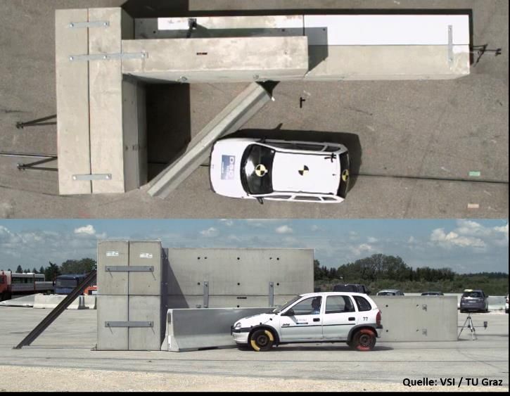
Infrastructures 2021, 6, 81 2 of 21
most frequent in unidirectional tunnels [6]. In Austria, similar findings can be observed:
Single vehicle accidents in unidirectional tunnels have a share of 61.8% at the portal and
26.3% in the tunnel [3]. On average, 30 persons in passenger cars are killed on motorways
and expressways every year. One person is killed every year due to collisions at the tunnel
Infrastructures 2021, 6, x FOR PEER REVIEW
portal or at the end-wall of a tunnel lay-by. Road user fatalities only count as fatal if the 2 of
injured persons die within 30 days after the road accident [15].
Figure
Figure 1. 1.Tunnel
Tunnel accident
accident at the
at the end-wall
end-wall ofunprotected
of an an unprotected tunnel
tunnel lay-bylay-by (Source:
(Source: Fire Brigade
Fire Brigade
Koper in Kunc et al.
Koper in Kunc et al. [2]).[2]).
InAustrian
Table 1 a detailed summary
motorways andofexpressways
road accidents currently
in tunnels with
havea length of more than
132 tunnels with length
200 m on motorways and expressways in Austria is given [3]. Even
greater than 200 m [3]. The total length of these tunnels is 370 km, whichthough the number of
is 16.7% of th
accidents has increased since 2012, the number of fatalities shows a decreasing tendency.
total length of motorways and expressways in Austria. The risk being fatally injured in
Three road users were killed in tunnel accidents in the past five years. Further, Strnad
tunnel
and is 1.6[3]
Schmied times higher
analysed than oninmotorways
accidents tunnels withand expressways
a length roads
of more than 500that are not
m (Table 2). enclose
[3]. These
Between oneresults
and twoare comparable
road with
user fatalities werefindings
recordedofonother studies.
average The
in these authors
tunnels conclude
in the
that the risk of
period 2012 to 2016.an accident in a tunnel is lower compared to the open road but the injur
severity is significantly higher [4–8]. Specifically the risk being more severely injured
1. Accidents
higher
Table in tunnels
at the tunnel with a length
entrance of more
compared tothan 200 m on
accidents motorways
inside and expressways
the tunnel [4,6,9–14].inAlthoug
Austria [3].
rear-end collisions are predominant inside the tunnel, single vehicle accidents are th
most frequent
Accident Yearaccident type at the tunnelInjured
Accidents entrance
Road[4,6,11,14].
Users In particular
Fatalities single vehic
accidents are most frequent in unidirectional tunnels [6]. In Austria, similar findings ca
2002 95 156 13
be observed:
2003 Single vehicle 93 accidents in unidirectional
154 tunnels have 4a share of 61.8% a
the portal
2004and 26.3% in the tunnel
133 [3]. On average,
23130 persons in passenger
6 cars are kille
2005 112 201 7
on motorways and expressways every year. One person is killed every year due to coll
2006 69 128 4
sions at2007
the tunnel portal or96 at the end-wall of a180tunnel lay-by. Road3 user fatalities onl
count as2008
fatal if the injured persons
84 die within 30155
days after the road accident
6 [15].
In 2009 60
Table 1 a detailed summary 121 in tunnels with a 7length of more tha
of road accidents
2010 75
200 m on motorways and expressways in Austria108 4
is given [3]. Even though the number o
2011 48 80 5
accidents
2012has increased since
1102012, the number of
168fatalities shows a decreasing
7 tendenc
Three road
2013 users were killed99 in tunnel accidents in
173the past five years. 3Further, Strnad an
Schmied 2014 105 in tunnels with167
[3] analysed accidents a length of more than 3 500 m (Table 2
2015 110 163 1
Between one and two road user
2016 137 fatalities were recorded
213 on average in3these tunnels in th
period 2012 to 2016.
A new data collection methodology was introduced in 2012—the accident data man
agement (UDM: Unfalldatenmanagement) [15]. The number of slightly and severely in
jured road users thus showed an enormous difference in 2012 compared to the previou
years. It is assumed that the UDM data collection has been improved and the reporte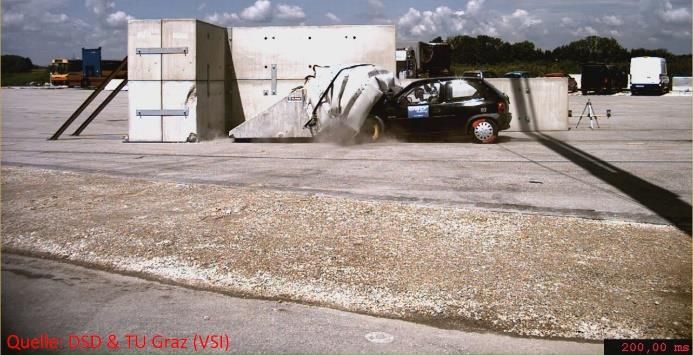
Infrastructures 2021, 6, 81                                                                                                    3 of 21

      Table 2. Accidents in tunnels with a length of more than 500 m on motorways and expressways in Austria separated in
      bi-directional and unidirectional tunnels [3].

                                          Bi-Directional Tunnels                              Unidirectional Tunnels
                                              Injured Road                                        Injured Road
  Accident Year               Accidents                            Fatalities     Accidents                            Fatalities
                                                  Users                                               Users
        2006                     14                20                  3              54               106                 1
        2007                     20                51                  0              71               119                 3
        2008                     23                49                  0              56                99                 6
        2009                     27                74                  4              27                39                 2
        2010                     18                27                  0              40                56                 3
        2011                     13                29                  4              29                41                 1
        2012                     28                56                  4              78               105                 2
        2013                     24                45                  2              71               123                 1
        2014                     12                21                  2              82               120                 1
        2015                     11                19                  1              83               121                 0
        2016                     14                41                  0             113               158                 1

                                            A new data collection methodology was introduced in 2012—the accident data man-
                                      agement (UDM: Unfalldatenmanagement) [15]. The number of slightly and severely injured
                                      road users thus showed an enormous difference in 2012 compared to the previous years. It
                                      is assumed that the UDM data collection has been improved and the reported accidents are
                                      based on a level of recording accuracy, which in all probability was not equaled in previous
                                      years. The introduction of UDM had no influence on the reported fatal accidents.
                                            Although the number of fatalities in tunnels is comparatively low, the Austrian Traffic
                                      Safety Programme 2011-2020 has introduced tunnel safety as a major priority issue [16].
                                      Furthermore, ASFINAG the Austrian commercial operator and builder of motorways and
                                      expressways announced in its Traffic Safety Programme that tunnel safety would be a
                                      priority issue in 2020 [17].
                                            Due to fire catastrophes in tunnels [18–20] caused by vehicle crashes [21] much at-
                                      tention was paid to fire accidents. Even though fire crashes are less frequent than traffic
                                      accidents the potential for a catastrophe is much higher in these cases [5,20,22–27]. Fur-
                                      thermore the geometry of tunnel lay-bys and tunnel portals received attention [18]. This
                                      especially because the end-wall of the tunnel lay-by was not protected with a safety mea-
                                      sure. This leads to the following questions: ‘What would be an appropriate design of
                                      the end-wall of a lay by or the tunnel portal’? ‘Which safety measures are appropriate to
                                      reduce the injury severity in case of a collision’?
                                            A number of safety measures are currently available at tunnel lay-bys and –portals (e.g.
                                      crash cushions, concrete barriers, guardrails, etc.) to protect occupants in passenger cars
                                      (examples are given in Figures 2–4. However, only a small number of studies investigated
                                      the performance of safety measures for lay-bys and portals [2,28]. Kunc et al. [2,28]
                                      investigated the safety performance of a steel guardrail and a crash cushion (Figure 2b) and
                                      Figure 3b) at different impact angles. For the steel guardrails they analysed two different
                                      horizontal inclinations (17◦ and 35◦ ). The safety assessment was based on the Finite
                                      Element Method (FEM). The assessment was based on a comparison with impacts against
                                      an unprotected end-wall of the tunnel lay-by. Gabauer and Thompson [29] evaluated
                                      full scale crash tests from the National Highway Traffic Safety Administration (NHTSA)
                                      according to impact severity levels ASI and THIV of EN 1317-2 [30].
                                            Studies on the performance of single elements of concrete barrier restraint systems
                                      (Figure 4) are not available. Furthermore there are no studies on the performance of steel
                                      guardrails or concrete barrier restraint systems that do not have the minimum installation
                                      length. To assess the impact severity level of road restraint systems (RRS), tests on restraint
                                      systems with a minimum installation length were evaluated [31–36]. Further studies used
                                      FEM or multi body simulations for the assessment of the injury level [34,37] or used the
                                      physical tests for validation of the simulation models [35,36,38,39]. An average minimum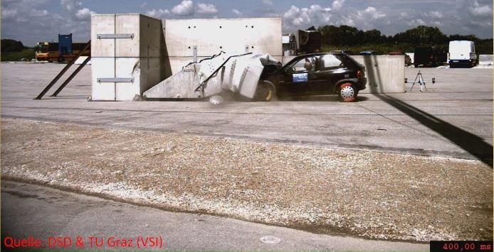
length. To assess the impact severity level of road restraint systems (RRS), tests on re-
straint systems with a minimum installation length were evaluated [31–36]. Further stud-
straint systems with a minimum installation length were evaluated [31–36]. Further stud-
ies used FEM or multi body simulations for the assessment of the injury level [34,37] or
ies used FEM or multi body simulations for the assessment of the injury level [34,37] or
used the physical tests for validation of the simulation models [35,36,38,39]. An average
used the physical tests for validation of the simulation models [35,36,38,39]. An average
minimum installation length of steel guardrails is approximately 76 m (Standard Devia-
minimum installation length of steel guardrails is approximately 76 m (Standard Devia-
Infrastructures 2021, 6, 81 tion (SD): 29) and concrete barriers have an average minimum installation length of4 ap- of 21
tion (SD): 29) and concrete barriers have an average minimum installation length of ap-
proximately 82 m (SD=29). These numbers are calculated from approximately 150 differ-
proximately 82 m (SD=29). These numbers are calculated from approximately 150 differ-
ent RRS used in Austria [40].
ent RRS used in Austria [40].
The safety level of in-situ concrete [41] to protect a vehicle colliding with the end-
The safety
installation level
length of in-situ
of steel concreteapproximately
guardrails [41] to protect76a m
vehicle colliding with the end-
wall of a tunnel lay-by is not publiclyisavailable. (Standard
However, in-situ Deviation
concrete (SD):
restraint 29)
sys-
wall of a tunnel lay-by is not publiclyminimum
available.installation
However, in-situ concrete restraint82
sys-
tems [40] just meet the impact severity level “B” of EN 1317-2 [30] with a maximum al-m
and concrete barriers have an average length of approximately
tems
(SD =[40]
29).just meet the impact
These severity level “B” of EN 1317-2150[30]different
with a maximum al-
lowed ASI of 1.4. Itnumbers are that
is expected calculated from
the protectionapproximately
of the tunnel lay-by RRSwith
end-wall usedin-
in
lowed
AustriaASI of 1.4. It is expected that the protection of the tunnel lay-by end-wall with in-
[40].
situ concrete would have a similar protection level.
situ concrete would have a similar protection level.
(a) (b)
(a) (b)
Figure
Figure2.2.Crash
Crashcushion
cushionpositioned
positionedin in
front of of
front thethe
end-wall of aoflay-by
end-wall (a) (a)
a lay-by [42][42]
andand
geometrical model
geometrical a crash
model cushion
a crash (b)
cushion
Figure 2. Crash cushion positioned in front of the end-wall of a lay-by (a) [42] and geometrical model a crash cushion (b)
[2,28].
(b) [2,28].
[2,28].
Infrastructures 2021, 6, x FOR PEER REVIEW 5 of 21
(a) (b)
(a) (b)
Figure 3. Protection measures of the tunnel lay-by end-wall. (a) protection of the edge of the end-wall with in-situ concrete
Figure 3. Protection measures of the tunnel lay-by end-wall. (a) protection of the edge of the end-wall with in-situ concrete
(a) [41] or angled concrete barrier (b) [2,28].
(a) [41] or angled concrete barrier (b) [2,28].
(a) (b)
Figure
Figure 4.4.Tunnel
Tunnellay-by
lay-byprotection measure.
protection (a) (a)
measure. angular positioned
angular concrete
positioned barrier
concrete [43] [43]
barrier and and
(b) crash cushion
(b) crash at theatend-
cushion the
wall of the tunnel lay-by [41].
end-wall of the tunnel lay-by [41].
Some countries (Spain, France, Italy, Slovenia) reported the use of angled barriers
(steel or concrete) with different length or crash cushions to mitigate the consequences in
case of a collision [41]. Steel guardrails and crash cushions are mounted to the tunnel wall
or to the road. Concrete barriers are positioned in front of the end-wall of the tunnel lay-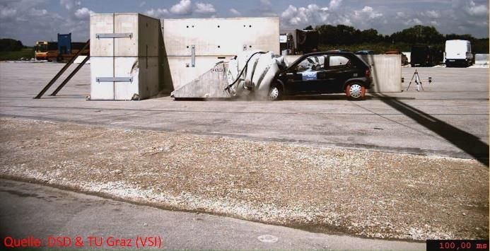
Infrastructures 2021, 6, 81                                                                                             5 of 21

                                    The safety level of in-situ concrete [41] to protect a vehicle colliding with the end-wall
                              of a tunnel lay-by is not publicly available. However, in-situ concrete restraint systems [40]
                              just meet the impact severity level “B” of EN 1317-2 [30] with a maximum allowed ASI of
                              1.4. It is expected that the protection of the tunnel lay-by end-wall with in-situ concrete
                              would have a similar protection level.
                                    Some countries (Spain, France, Italy, Slovenia) reported the use of angled barriers
                              (steel or concrete) with different length or crash cushions to mitigate the consequences in
                              case of a collision [41]. Steel guardrails and crash cushions are mounted to the tunnel wall
                              or to the road. Concrete barriers are positioned in front of the end-wall of the tunnel lay-by.
                              In Austrian tunnels, in particular, concrete barriers with a length of 4 m and crash cushions
                              are predominantly used. For maintenance reasons (e.g., no damage of power supply
                              connections beneath the road, quickly mounting and demounting of the crash cushion) it
                              is required that crash cushions are not anchored to the road on Austrian motorways and
                              expressways. With the regulations RVS 09.01.24 [44] and RVS 09.01.25 [45] launched 2014
                              and 2015 respectively the goal is to harmonize tunnel portal and tunnel lay-by design and
                              guarantee the best possible protection in the event of an impact. No studies concerning the
                              effectiveness of these measures (angular positioned concrete barriers, crash cushions not
                              used for a speed limit), however, are currently available.
                                    The objective of the present research project is to assess the safety effectiveness to
                              protect occupants of passenger cars of different protection measures for tunnel lay-bys and
                              portals for unidirectional tunnels with a speed limit of 100 km/h. The following safety
                              measures that are not directly anchored to the road surface, are investigated:
                              •    angular positioned 4 m concrete barrier (Figure 4),
                              •    angular positioned 8 m concrete barrier (Figure 4),
                              •    non-redirective crash cushion Alpina F1-50 not designed for this speed limit (Figure 2a),
                              •    non-redirective crash cushion Alpina  not designed for this speed limit
                                   (Figure 2a).
                                   The angular positioned 4 m concrete barrier is to be tested, because this safety mea-
                              sure is commonly used to avoid collisions with an unprotected end-wall of the tunnel
                              lay-by. Subsequently the safety performance of an angular positioned concrete barrier
                              with a length of 8 m should be tested. There is no detailed information on how often
                              a crash cushion Alpina F1-50 is used at tunnel portals or lay-bys but a relatively large
                              number of thesedevices are installed on motorways and expressways. Further an improved
                              crash cushion labelled as  is to be tested to assess if there is an improved
                              protection determinable.

                              2. Materials and Methods
                                   Figure 5 represents the flowchart of the methodology. In a first step an accident
                              analysis of the Central Database for In-Depth Accident Studies (CEDATU) was performed
                              to obtain the impact configurations in terms of run-off-road angle and impact angle. The
                              impact speed was defined to correspond with the common speed limits in tunnels in
                              Austria. The impact point and specifications for the test vehicles obtained from the EN
                              1317-1 [30,46] and EN 1317-3 [47]. Finally the assessment was carried out on the basis of
                              the 1317-2 [30] and 1317-3 [47] criteria and conclusions and recommendations were drawn.

                              2.1. Impact Configuration
                                   The tunnel lay-by is rebuild with concrete blocks which are anchored to the road
                              surface (Figure 6). The width of the tunnel lay-by is 2.7 m according to the Austrian
                              standard RVS 09.01.24 [44]. At the side of the test area concrete barriers were positioned to
                              prevent the vehicle from leaving the test site.
                                   The run-off-road angle is calculated based on real-world accidents of the CEDATU
                              database [48,49]. A run-off-road angle is calculated on average as 5.4◦ (SD: 4.1) with a
                              run-off-road velocities of between 95 km/h and 105 km/h. A maximum run-off-road angle
                              of 16◦ was observed. Based on theoretical considerations of Hoschopf and Tomasch [50] a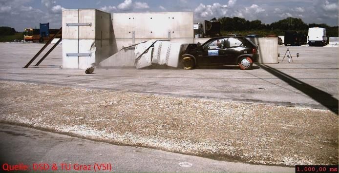
2. Materials and Methods
Figure 5 represents the flowchart of the methodology. In a first step an accident anal-
Infrastructures 2021, 6, 81
ysis of the Central Database for In-Depth Accident Studies (CEDATU) was performed6 to of 21
obtain the impact configurations in terms of run-off-road angle and impact angle. The
impact speed was defined to correspond with the common speed limits in tunnels in Aus-
tria. The impact
maximum point andangle
run-off-road specifications
at 100 km/hfor the test vehicles
run-off-road obtained
speed from the
is calculated toEN
5.4◦1317-
at dry
1 [30,46]
road (road friction = 0.7) road conditions. For the tests the run-off-road angle is setoftothe
and EN 1317-3 [47]. Finally the assessment was carried out on the basis 5◦ .
1317-2 [30] and 1317-3 [47] criteria and conclusions and recommendations were drawn.
Infrastructures 2021, 6, x FOR PEER REVIEW 7 of 21
Figure 5. 5.
Figure Flow chart
Flow of of
chart thethe
Methodology.
Methodology.
2.1. Impact Configuration
The tunnel lay-by is rebuild with concrete blocks which are anchored to the road
surface (Figure 6). The width of the tunnel lay-by is 2.7 m according to the Austrian stand-
ard RVS 09.01.24 [44]. At the side of the test area concrete barriers were positioned to pre-
vent the vehicle from leaving the test site.
The run-off-road angle is calculated based on real-world accidents of the CEDATU
database[48,49]. A run-off-road angle is calculated on average as 5.4° (SD: 4.1) with a run-
off-road velocities of between 95 km/h and 105 km/h. A maximum run-off-road angle of
16° was observed. Based on theoretical considerations of Hoschopf and Tomasch [50] a
maximum run-off-road angle at 100 km/h run-off-road speed is calculated to 5.4° at dry
road (road friction=0.7) road conditions. For the tests the run-off-road angle is set to 5°.
The position of the concrete barrier is based on the length of the barrier and the width
of the tunnel lay-by (Figure 6). For the 4 m barrier the positioning angle is 42° and for the
8 m barrier 18°. The collision angle calculated from the positioning angle and the run-off-
road angle is 47° for the 4 m barrier and 23° for the 8 m barrier. The positioning angle of
the crash cushion is set at 5° so that the vehicle impacts the crash cushion at an angle of
0°. The energy absorbing structure (“cushion bag”) of the crash cushion is mounted to a
triangular shaped concrete wall, which is termed the “back-up”. The crash cushion is po-
sitioned approximately 1.0 m ahead of the end-wall of the tunnel lay-by.
The impact point is defined so that the right front corner of the vehicle impacts the
middle point of the concrete barrier. The impact point for the crash cushion is at the centre
line so that the vehicle impacts the crash cushion with a full frontal overlap.
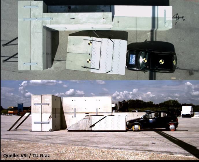
(a) (b)
Figure
Figure 6.
6. Test
Test set-up for an angular
angular positioned
positionedconcrete
concretebarrier
barrierand
andvehicle
vehicleposition
positionatatfirst
firstcontact
contact(a)(a) and
and the
the crash
crash cush-
cushion
ion with the vehicle position at the first contact
with the vehicle position at the first contact (b). (b).
The
The impact
positionspeed
of theisconcrete
set to 100 km/h
barrier according
is based tolength
on the the speed
of thelimit of unidirectional
barrier and the width
tunnels. The speed
of the tunnel lay-byis (Figure
measured6). approximately 6 m before
For the 4 m barrier the vehicleangle
the positioning is 42◦the
impacted andcon-
for
crete
the 8barrier or the
m barrier ◦
18 crash
. Thecushion
collisioninangle
accordance withfrom
calculated the EN
the 1317-2 [30] and
positioning ENand
angle 1317-3
the
run-off-road angle is 47◦ for the 4 m barrier and 23◦ for the 8 m barrier. The positioning
[47].
angle ofthe
For thetests
crash cushion
vehicles is setOpel
(here: ◦ so that
at 5Corsa) thethe vehicle
TB11 impacts the
requirements crash
(kerb mass cushion at
of 825+/-
ankg)
angle ◦
of 01317-1
. The[46]
energy absorbing structure (“cushion bag”) of the crash cushion is
40 of EN are used.
An ATD (anthropomorphic test device) was placed on the driver’s seat. The ATD
represents a vehicle occupant in shape, size and mass to reproduce the dynamic behavior
of an occupant during the crash. The mass of the ATD is 75 kg.
2.2. Test Specimen
Concrete barriers from the company REBLOC were used as angular positioned safety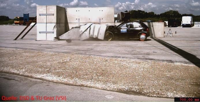
Infrastructures 2021, 6, 81                                                                                             7 of 21

                              mounted to a triangular shaped concrete wall, which is termed the “back-up”. The crash
                              cushion is positioned approximately 1.0 m ahead of the end-wall of the tunnel lay-by.
                                    The impact point is defined so that the right front corner of the vehicle impacts the
                              middle point of the concrete barrier. The impact point for the crash cushion is at the centre
                              line so that the vehicle impacts the crash cushion with a full frontal overlap.
                                    The impact speed is set to 100 km/h according to the speed limit of unidirectional
                              tunnels. The speed is measured approximately 6 m before the vehicle impacted the concrete
                              barrier or the crash cushion in accordance with the EN 1317-2 [30] and EN 1317-3 [47].
                                    For the tests vehicles (here: Opel Corsa) the TB11 requirements (kerb mass of 825+/−40 kg)
                              of EN 1317-1 [46] are used.
                                    An ATD (anthropomorphic test device) was placed on the driver’s seat. The ATD
                              represents a vehicle occupant in shape, size and mass to reproduce the dynamic behavior
                              of an occupant during the crash. The mass of the ATD is 75 kg.

                              2.2. Test Specimen
                                   Concrete barriers from the company REBLOC were used as angular positioned safety
                              measure. According to the product description [51] the concrete barriers have an H2
                              containment level, working with W5 and an impact severity level of “B” according to EN
                              1317-2 [30]. The barriers have a length of 4000 mm or 8000 mm respectively, a width of
                              640 mm and a height of 1000 mm. The weight of the 4 m barrier is 3000 kg and 6000 kg for
                              the 8 m barrier. The minimum installation length of a RRS with a barrier length of 4 m is
                              64 m and of 8 m is 104 m.
                                   Non-directive cushions from the company ALPINA were used as crash cushions.
                              These retain but do not redirect vehicles. The first crash cushion used is an Alpina F1-50
                              with the performance level 50 according to EN 1317-3 [47]. The impact severity class is “B”.
                              The crash cushion has a width of 2400 mm, a length of 3.380 mm (cushion bag: 1580 mm,
                              back-up: 1800 mm) and a height of 1000 mm [52]. The  crash cushion has
                              the performance level 80. The crash cushion is approximately 0.5 m longer than the crash
                              cushion F1-50. No further information can be given.
                                   For each protection measure one test is performed. The test matrix is given in Table 3.

                              Table 3. Test matrix of the performed tests.

                                                                             Vehicle     Impact Speed       Impact Angle
                                        Concrete barrier 4 m                  TB11         100 km/h               47◦
                                        Concrete barrier 8 m                  TB11         100 km/h               23◦
                                    Crash cushion Alpina F1-50                TB11         100 km/h               0◦
                                 Crash cushion Alpina              TB11         100 km/h                0◦

                              2.3. Data Acquisition
                                   For the assessment, multiple accelerometers with different measurement ranges were
                              used. One tri-axial transducer (manufacturer: ASC; type: 5411LN-100) was positioned
                              close to the vehicle’s centre of gravity. The measurement range of these transducers is
                              100 g. Two further tri-axial transducers (manufacturer: Measurement Specialities; type:
                              1203-0500-10-240X) were positioned close to the vehicle’s centre of gravity for redundancy
                              reasons. The measurement range of these transducers is 500 g. Further to this an angular
                              velocity sensor (rate sensor) (manufacturer: IES; type: 3103-2400) was equipped close to
                              the centre of gravity. The maximum range of the velocity sensor is 2 400◦ /s. All of the
                              transducers were mounted on a metal plate, which was mounted to the vehicle’s centre
                              of gravity (Figure 7b). All the transducers were calibrated. The coordinate system of the
                              vehicle was defined according to EN 1317-1 [46] (Figure 7b).
                                   For data acquisition a K3700 Minidau®(Mini Data Acquisition Unit) from Kayser-
                              Threde with a sampling rate of 10 kHz was used. The measurement as synchronized with
                              high-speed cameras to enable a analysis by a contact switch in the front of the test vehicle
                              that starts the DAQ and simultaneously triggers a flash-light.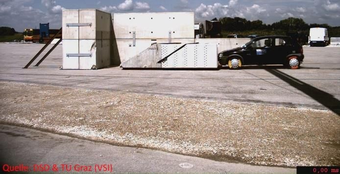
transducers were mounted on a metal plate, which was mounted to the vehicle’s centre of
gravity (Figure 7b). All the transducers were calibrated. The coordinate system of the ve-
hicle was defined according to EN 1317-1 [46] (Figure 7b).
For data acquisition a K3700 Minidau® (Mini Data Acquisition Unit) from Kayser-
Infrastructures 2021, 6, 81 Threde with a sampling rate of 10 kHz was used. The measurement as synchronized8with of 21
high-speed cameras to enable a analysis by a contact switch in the front of the test vehicle
that starts the DAQ and simultaneously triggers a flash-light.
y
x
Tri-axial transducer Angular velocity sensor
(a) (b)
Figure
Figure 7.
7. Vehicle
Vehicle coordinate
coordinate system (a) and
system (a) and position
position of
of the
the acceleration
acceleration transducers
transducers mounted
mounted at
at the
the center
center of
of gravity
gravity (b).
(b).
Three high
Three high speed
speed cameras
cameras capture
capture the
the vehicle
vehicle motion
motion atatdifferent
differentpositions.
positions. One
One
panned camera was positioned perpendicular to the test object at the impact
panned camera was positioned perpendicular to the test object at the impact point i.e., to point i.e. to
the path
the path ofof the
the vehicle
vehicle at
at normal
normal speed.
speed. The
The high
high speed
speed video
video cameras
cameras are
are operated
operated with
with
aa rate
rate of
of 500
500 frames
frames per
per second.
second. One
One high
high speed
speed camera
camera isis positioned
positioned overhead
overhead toto cover
cover
the vehicle
the vehicle motion
motion atat the
the impact
impact point.
point. One high speed
speed camera
camera is positioned
positioned at
at aa point
point
behind the
behind the impact
impactin inorder
ordertotorecord
recordvehicle
vehicleroll
rolland
and vertical
vertical lift.
lift. OneOne high
high speed
speed camera
camera is
is positioned
positioned to capture
to capture thethe lateral
lateral motion.
motion.
2.4.
2.4. Assessment
Assessment
The assessment of
The assessment ofthe
thedifferent
differentsafety
safetymeasures
measuresis is based
based onon criteria
criteria defined
defined in the
in the EN
EN
1317-2 [30] and EN 1317-3 [47]. Following criteria are assessed applicable to thesethese
1317-2 [30] and EN 1317-3 [47]. Following criteria are assessed applicable to tests:
tests: the severity
the severity indices
indices ASI (Acceleration
ASI (Acceleration Severity
Severity Index)Index)
and THIV THIV (Theoretical
and(Theoretical Head
Head Impact
Impact Velocity).
Velocity). !2 !2 !2 0.5
A x A y A z
ASI (k) = + + (1)
12 9 10
h i0.5
TH IV = Vx2 ( T ) + Vy2 ( T ) (2)
The ASI is a function of acceleration and time and is intended to assess the severity of
the vehicle motion for an occupant during an impact.
The THIV is used to assess the occupant impact severity in a vehicle in impacts with
RRS. It is assumed that the head of the occupant is free to move. In the event of an impact
the vehicle changes speed and motion direction, while the head of the occupant keeps to
the pre-crash trajectory and continues moving until striking the interior of the vehicle. The
magnitude of the velocity of the theoretical head impact is considered to be a measure of
the vehicle-to-vehicle restraint system impact severity.
The limits of ASI and THIV are given in Table 4 (safety barriers) and Table 5 (crash
cushions). Impact severity level “A” has a greater safety level for the occupants of an
errant vehicle and impact severity “B” has a greater safety level than “C”. In Austria the
minimum impact severity level “B” is required [44].
Table 4. Impact severity limits of safety barriers according to EN 1317-2 [30].
Impact Severity Level Index Values
A ASI ≤ 1.0
B ASI ≤ 1.4 and THIV ≤ 33 km/h
C ASI ≤ 1.9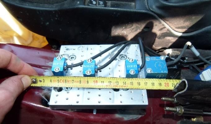
Infrastructures 2021, 6, 81                                                                                                 9 of 21

                              Table 5. Impact severity limits of crash cushions according to EN 1317-3 [47].

                                    Impact Severity Level                               Index Values
                                                 A                   ASI ≤ 1.0
                                                 B                   ASI ≤ 1.4
                                                                                          and                  THIV ≤ 44 km/h 1
                              1   value valid for frontal impacts.

                                   Moreover, the behavior and deformation of the safety barrier or crash cushion as
                              well as the test vehicle behavior and deformation are taken into account. The following
                              assessment criteria are thereby evaluated:
                                   After the impact the vehicle should be redirected without complete breakage of the
                              elements of the restraint-system having occurred. No parts of the restraint system should
                              penetrate the passenger compartment.
                                   The test vehicle should remain upright during and after the impact. Moderate rolling,
                              pitching and yawing are acceptable. The post-crash motion of the vehicle should be controlled.
                                   Deformation of the passenger compartment or intrusions into the passenger compart-
                              ment are not permitted.

                              3. Results
                              3.1. Concrete Barrier 4 m
                                    The top of the concrete barrier had a contact with the end-wall of the tunnel lay-by due
                              to the impact. This is disadvantageous for the vehicle kinematics in terms of supporting
                              the vehicle lift up. After the impact the vehicle was redirected according to the positioning
                              angle of the barrier. The vehicle was lifted up and rotated approximately 90◦ counter
                              clockwise to its own longitudinal axis. At the side of the test area concrete barriers were
                              positioned to prevent the vehicle from leaving the test site. The vehicle impacted these
                              concrete barriers with its roof upside-down. The maximum distance of the vehicle to the
                              road surface during the flight phase is roughly 1.4 m (Figure 8). The flight distance after
                              the impact to the safety fence is approximately 14 m. The right A-pillar and the header
                              rail are damaged and passenger compartment intrusions were observed. The acceleration
                              index ASI was calculated to 2.9 and THIV is calculated to 53 km/h. The change of velocity
                              (delta-v) is 43 km/h. The post-crash speed was approximately 57 km/h.

                              3.2. Concrete Barrier 8 m
                                   After the impact, the vehicle was lifted from the road surface and had a flight height
                              of approximately 0.5 m (Figure 9). The vehicle had a high pitching angle and the rear
                              wheels had a maximum height of approximately 1.0 m. The flight distance of the vehicle
                              was approximately 10 m. In the rollout phase, the vehicle impacted the concrete barriers
                              positioned to prevent the vehicle to leave the test site with the front of the vehicle. No
                              intrusions into the passenger compartment were observed. The ASI is calculated to 1.6 and
                              THIV is calculated to 30 km/h. The change of velocity is 22 km/h resulting in a speed after
                              the impact of approximately 78 km/h.

                              3.3. Crash Cushion Alpina F1-50
                                    The vehicle w fully decelerated (Figure 10). At the time when the vehicle stopped the
                              crash cushion was pushed forward into the end-wall of the tunnel lay-by. Simultaneously
                              the vehicle started to accelerate against the pre-crash motion direction due to the elastic
                              restitution of the vehicle and the crash cushion. The final rest position was approximately
                              0.4 m in front of the damaged crash cushion. During the impact the wheels were lifted
                              approximately 0.5 m above the road surface.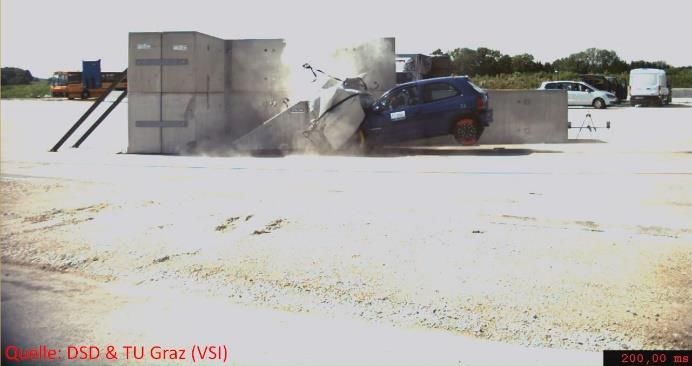
to the road surface during the flight phase is roughly 1.4 m (Figure 8). The flight distance
                                  after the impact to the safety fence is approximately 14 m. The right A-pillar and the
Infrastructures 2021, 6, 81       header rail are damaged and passenger compartment intrusions were observed. The       10 of 21
                                                                                                                            ac-
                                  celeration index ASI was calculated to 2.9 and THIV is calculated to 53 km/h. The change
                                  of velocity (delta-v) is 43 km/h. The post-crash speed was approximately 57 km/h.

      Figure 8. Vehicle motion impacting a 4 m concrete barrier. The vehicle impacts the barrier, lifts up and is rotating counter
      Figure 8. Vehicle motion impacting a 4 m concrete barrier. The vehicle impacts the barrier, lifts up and is rotating counter
      clockwise to its own longitudinal axis and redirected into the road lane.
      clockwise to its own longitudinal axis and redirected into the road lane.
                                  3.2. Concrete  Barrier
                                         The crash       8 m was deformed up to its full energy absorption capability. The
                                                     cushion
                                        After
                                  vehicle   wasthe impact, up
                                                 damaged    theto
                                                                vehicle  waswheels
                                                                  the front   lifted from
                                                                                      and thethewheels
                                                                                                 road surface   and had atoflight
                                                                                                        were displaced              height
                                                                                                                             the sill.  The
                                  of  approximately
                                   facia               0.5 m into
                                          panel was pushed     (Figure
                                                                    the 9). The vehicle
                                                                         passenger          had a highThe
                                                                                      compartment.       pitching
                                                                                                             left andangle  and the
                                                                                                                       the right       rear
                                                                                                                                  A-pillar
                                  wheels   had a maximum
                                  were damaged                heightwere
                                                    and the header     of approximately      1.0 m. The
                                                                           rails slightly buckled.   The flight
                                                                                                         bonnet  distance  of theback
                                                                                                                   was pushed      vehicle
                                                                                                                                        and
                                  was   approximately
                                   the windscreen    was10   m. In theThe
                                                          smashed.      rollout
                                                                           driverphase,   the vehicle
                                                                                   seat rails         impactedand
                                                                                               were destroyed      thethe
                                                                                                                       concrete   barriers
                                                                                                                           seat including
                                  positioned
                                   the dummytowas  prevent  the vehicle
                                                      projected  forwardto   leave the
                                                                           against   the facia
                                                                                          test site with
                                                                                               panel. ThetheASIfront  of the vehicle.
                                                                                                                 is calculated          No
                                                                                                                                to 3.3 and
                                  intrusions   into the to
                                  THIV is calculated     passenger
                                                           74 km/h.compartment were observed. The ASI is calculated to 1.6
                                  and THIV is calculated to 30 km/h. The change of velocity is 22 km/h resulting in a speed
                                   3.4. Crash
                                  after       Cushion
                                         the impact  of Alpina
                                                        approximately     78 km/h.
                                         Within the test the vehicle was fully decelerated (Figure 11). After the vehicle came to
                                   a stop, the crash cushion was thrust against the tunnel lay-by. From this point in time the
                                  vehicle moved backwards and the final position reached was at 0.6 m in front of the crash
                                   cushion. No lift of the rear wheels was observed.
                                         The crash cushion was deformed up to its full energy absorption capability and the
                                   front of the vehicle was damaged. No contact of the wheels with the sill was observed. No
                                   intrusions into the passenger compartment were observed. The ASI is calculated at 1.8 and
                                  THIV is calculated at 57 km/h.

                                  3.5. Summary of the Test Results
                                        A summary of the results of the tests is given in Table 6.
Infrastructures 2021, 6, 81 11 of 21
Infrastructures 2021, 6, x FOR PEER REVIEW 11 of 21
Figure 9. Vehicle motion impacting a 8 m concrete barrier. The vehicle impacted the barrier and was deflected upwards.
Figure 9. Vehicle
The vehicle motiontoimpacting
was rotated the y-axisa(pitching)
8 m concrete
andbarrier.
the rearThe vehicle
wheels hadimpacted the
a height of barrier and was
approximately 1.0 deflected
m. upwards.
The vehicle was rotated to the y-axis (pitching) and the rear wheels had a height of approximately 1.0 m.
3.3. Crash Cushion Alpina F1-50
The vehicle w fully decelerated (Figure 10). At the time when the vehicle stopped the
crash cushion was pushed forward into the end-wall of the tunnel lay-by. Simultaneously
the vehicle started to accelerate against the pre-crash motion direction due to the elastic
restitution of the vehicle and the crash cushion. The final rest position was approximately
0.4 m in front of the damaged crash cushion. During the impact the wheels were lifted
approximately 0.5 m above the road surface.
The crash cushion was deformed up to its full energy absorption capability. The ve-
hicle was damaged up to the front wheels and the wheels were displaced to the sill. The
facia panel was pushed into the passenger compartment. The left and the right A-pillar
were damaged and the header were rails slightly buckled. The bonnet was pushed backInfrastructures 2021, 6, x FOR PEER REVIEW 12 of 21
Infrastructures 2021, 6, 81 and the windscreen was smashed. The driver seat rails were destroyed and the seat
12 ofin-
21
cluding the dummy was projected forward against the facia panel. The ASI is calculated
to 3.3 and THIV is calculated to 74 km/h.
Figure 10. Vehicle motion impacting the crash cushion Alpina F1-50. The vehicle was fully decelerated and moved back-
Figure Vehicle
10. to
wards due motion
the elastic impacting
restitution. Thethe crash
final cushion
position wasAlpina F1-50. The
approximately 0.4 mvehicle was
in front fully
of the decelerated
damaged crashand moved
cushion.
backwards due to the elastic restitution. The final position was approximately 0.4 m in front of the damaged crash cushion.
3.4. Crash Cushion Alpina
Table 6. Summary of the results of the assessment of the safety measures.
Within the test the vehicle was fully decelerated (Figure 11). After the vehicle came
to a stop, the crash cushion
Barrier 4 m
was thrust againstCrash
Barrier 8 m
the tunnel lay-by. FromCrash
Cushion this point in time
Cushion
the vehicle moved backwards and the final position F1-50
reached was at 0.6
m in front of the
ASI (Limit for severity crash cushion. No lift of the rear wheels was observed.
2.9 1.6 3.3 1.8
level “B”: 1.4) The crash cushion was deformed up to its full energy absorption capability and the
THIV (Limit a: front of the vehicle was damaged. No contact of the wheels with the sill was observed. No
33 km/h for safety
intrusions into the passenger compartment were observed. The ASI is calculated at 1.8
barriers and b: 53 30 74 57
44 km/h for and THIV is calculated at 57 km/h.
crash cushions)
Vehicle lifts up and
Secondary impact impacts the end-wall of Vehicle lifts up No secondary impact No secondary impact
tunnel lay-by
Vehicle rotates and is No vehicle rotation but Vehicle moved Vehicle moved
redirected into the road is redirected into the backwards and was backwards and was
Post crash kinematics
lane and impacts left road lane and impacts rotating around the rotating around the
tunnel wall left tunnel wall vertical axis vertical axis
Test vehicle behavior
Uncontrolled Uncontrolled Yawing Yawing
after the impact
Test vehicle
Intrusions No intrusions Intrusions No intrusions
deformationInfrastructures 2021, 6, 81 13 of 21
Infrastructures 2021, 6, x FOR PEER REVIEW 13 of 21
Figure 11. Vehicle motion impacting the crash cushion Alpina . The vehicle was fully decelerated and moved
Figure 11. Vehicle motion impacting the crash cushion Alpina . The vehicle was fully decelerated and moved
backwards due to the elastic restitution. The final position was approximately 0.6 m in front of the damaged crash cushion.
backwards due to the elastic restitution. The final position was approximately 0.6 m in front of the damaged crash cushion.
3.5. Summary of the Test Results
4. Discussion
After the
A summary of impact withofthe
the results the4 tests
m concrete
is given barrier the6.vehicle is deflected upwards and a
in Table
secondary impact with the end-wall of the lay-by could occur as a result. When this does
Tablenot6. occur,
Summaryhowever, the vehicle
of the results of theisassessment
redirectedofinto the road
the safety lane with an angle corresponding
measures.
to the positioning angle of the concrete barrier. A secondary collision with the tunnel wall
on the left road lane will4 occur or the redirected Crash Cushion Crash Cushion
Barrier m Barrier 8 m vehicle might hit another road user. The
change of velocity at the primary impact is approximately F1-50
43 km/h and
the secondary
ASI (Limit for severity level impact
“B”: 1.4)at the left tunnel2.9 wall would be 1.6 at approximately 60 3.3km/h. After the 1.8impact the
THIV (Limit a): 33 km/h for safety barriers
vehicle rolled counter clockwise with a relatively high flight height and at the secondary
53 30 74 57
impact the occupants were out of position. Airbags might be already triggered at the
and b): 44 km/h for crash cushions)
primary impact and would
Vehicle thus have no protective function at the secondary impact. The
lifts up and
safety belt alsoimpacts
only provides
the end-optimal occupant protection if both airbag
No secondary im- and safety beltim-
No secondary are
Secondary impact Vehicle lifts up
still operationalwallinofa tunnel
coordinated
lay- manner and when the vehicle pact is in an upright pactposition.
According to the ENby 1317-2 [30] requirements a moderate rolling only is acceptable and
the post-crashVehicle
motion can then
rotates and be Nocontrolled. At the impact with the 4 m concrete barrier,
vehicle rotation
neither a moderate rolling,into
is redirected nor a controlled post-crashVehicle
but is redirected motionmoved Vehicle moved
were observed.
Intrusionstheinto the passenger compartment backwards and was backwards and was
Post crash kinematics road lane and into the road lane are not permitted. However, the right
A-pillar was damaged and intrusions rotating around the rotating around the
impacts left tunnel andvia the dashboard
impacts left are observed and would as a result
presumably have resulted vertical axis vertical axis
wall in severe injuries in real accidents.
tunnel wall
Although
Test vehicle behavior after the impact the vehicle
Uncontrolled did not show a rotational
Uncontrolled motion around the longitudinal
Yawing Yawing axis
Test vehicle deformation
at the 8 m concrete barrier,
Intrusions
it is still deflected
No intrusions
upwards due to
Intrusions
the impact. The vehicle is
No intrusions
redirected into the road after the impact with a run-out angle of 23◦ , which correspondsInfrastructures 2021, 6, 81 14 of 21
to the positioning angle of the barrier in the lay-by. The change of velocity to 22 km/h
is much lower compared to that with the 4 m concrete barrier. Thus the vehicle would
collide with the left tunnel wall at higher collision speed of approximately 78 km/h. When
impacting the 8 m concrete barrier, the vehicle remains upright with a high pitching angle
and only marginal rolling is observed.
The damage pattern of the vehicle for the impact against the Alpina F1-50 showed
intrusions into the passenger compartment. Thus, injuries to the lower extremities can be
expected in real accidents [53–55]. No intrusions in the test with the Alpina
were observed.
The impact severity level “B” requires an ASIASI is reduced from 2.9 for the 4 m concrete barrier to 1.6 for the 8 m concrete barrier. The
THIV is reduced from 53 km/h to almost 30 km/h. Similar results are observed for the
crash cushions. The ASI is reduced from 3.3 for the crash cushion Alpina F1-50 to 1.8 for
Infrastructures 2021, 6, 81 the Alpina . The THIV is reduced from 74 km/h to 58 km/h. Although 15 of 21 the
values decrease with increasing length of the safety measure the minimum length of the
tunnel lay-by must not be undercut.
(a) (b)
Figure 12. Relation
Figure between
12. Relation necessary
between installation
necessary installationspace
space of
of the specificsafety
the specific safety measure
measure andand
ASIASI (a) and
(a) and THIVTHIV
(b). It(b).
canItbecan be
notednoted
that ASI
that and THIV
ASI and areare
THIV reduced with
reduced withincreasing
increasing installation space.
installation space.
Table Corresponding
The7. extent to which risk of
ASIMAIS
and2+THIV
and MAIS
pose3+ [56] injuries of
a specific unbelted
risk and belted
of injury to an occupants
occupant
is
related to the ASI of the different safety measur.es.
indicated in Tables 7 and 8. Risk curves of Gabauer and Gabler [56] are used to assess the
injury risk. The injury risk curves are based on the Abbreviated
MAIS 2+ InjuryMAIS
Severity
3+ (AIS) and
were calculated for ASI and THIV. The injury thresholds
ASI Unbelted could
Belted be distinguished
Unbelted Beltedbetween
the maximum AIS of 2 or greater (MAIS 2+) and 3 (MAIS 3+). Furthermore, the risk curves
Unprotected wall [2] 3.7 100% 98% 100% 85%
were generated forbarrier
Concrete unbelted
4 m (airbag-only
2.9 restraint)
99% and 91%
belted occupants
97% (belted
60% and air-
bag restraint).
Concrete barrier 8 m 1.8 84% 56% 63% 21%
Crash cushion Alpina F1-50 3.3 100% 96% 99%
The collision against an unprotected end-wall of a tunnel lay-by data provided 75% by
Crash cushion Alpina 1.6 75% 46% 48% 15%
Kunc et al. [2] were used as a reference. Nearly all of the safety measures indicate a lower
risk of injury for the ASI injury risk curves (Table 7). The crash cushion Alpina F1-50 and
Table 8. Corresponding risk of MAIS 2+ and MAIS 3+ [56] injuries of unbelted and belted occupants related to the THIV of
the 4 m concrete barrier do not show a much better protection compared to an unprotected
the different safety measur.es.
wall. However, MAIS 3+ injuries for belted occupants are a little lower for these two safety
measures. It is clear that belted occupants
MAIS 2+have a lower risk of being MAIS injured.
3+ Similar find-
THIV
ings can be observed for theUnbelted Belted
THIV injury risk curves (TableUNBELTED
8). belted
Unprotected wall [2] 56 km/h 97% 73% 99% 38%
Concrete barrier risk
Table 7. Corresponding 4 m of MAIS 2+ and
53 km/h 96% of unbelted
MAIS 3+ [56] injuries 69% 97%
and belted occupants related to32%
the ASI of
Concrete barrier 8 m
the different safety measur.es 30 km/h 19% 18% 1% 5%
Crash cushion Alpina F1-50 74 km/h 100% 94% 100% 78%
Crash cushion Alpina 57 km/h 98% MAIS
2+ 77% 99%
MAIS 42%
3+
ASI Unbelted Belted Unbelted Belted
Unprotected wall [2] The collision
3.7 against an unprotected
100% end-wall
98% of a tunnel lay-by
100% data provided
85%by
Kunc et al. [2] were used as a reference. Nearly all of the safety measures indicate a lower
Concrete barrier 4 m risk of injury 2.9 99% 91% 97% 60%
for the ASI injury risk curves (Table 7). The crash cushion Alpina F1-50 and
Concrete barrier 8 m the 4 m concrete
1.8 barrier do not
84% 56%protection compared
show a much better 63% to an unprotected
21%
wall. However, MAIS 3+ injuries for belted occupants are a little lower for these two safety
measures. It is clear that belted occupants have a lower risk of being injured. Similar
findings can be observed for the THIV injury risk curves (Table 8).
Even if ASI and THIV were not be used as the main assessment criteria, in collisions
with a concrete barrier the vehicle will be redirected into the road lane which is considered
to be critical. The concrete barrier was rotated around the longitudinal axis until the top of
the barrier contacted the end-wall of the tunnel lay-by. This rotation supports the upwards
deflection of the vehicle. If this effect can be prevented, the vehicle might not lift up to
such a great extent and the vehicle rotation after the impact might also be prevented. The
redirection of the vehicle into the road lane, however, cannot be prevented with an angled
concrete barrier. For the crash cushions only a slight yaw rotation of the vehicle is observedInfrastructures 2021, 6, 81 16 of 21
from the top view camera. The center line of the vehicle equals the center line of the crash
cushion at the impact i.e., without an offset. Thus, the vehicle would rotate much more
when only a small part of the vehicle’s front impacts the crash cushion. A post-crash motion
into the road lane is expected. Following the test configurations of the EN 1317-3 [47] a
further frontal impact with an angle of 0◦ is mandatory for a CE conformity. In the course
of this test the vehicle should hit the crash cushion with a vehicle offset of 25% from the
center line of the crash cushion. In the case of the Alpina F1-50 or the Alpina
crash cushion the vehicle would still hit with a full overlap. The worst case, however,
would be an offset impact in which only 25% of the vehicle hits the crash cushion but
unfortunately tests of this kind are not foreseen in EN 1317-3 [47].
The impact was defined at the mid-point of the concrete barrier with a vehicle corre-
sponding to the TB11 weight requirements of EN 1317-1 [46] to evaluate if the concrete
barrier would be penetrated. No damage of the latter i.e., penetration is observed. The
vehicle kerb weight of all newly registered passenger cars in Germany has been increasing
in recent years and reached an average of approximately 1515 kg in 2018 [57]. An analysis
of 110 different vehicles tested at Euro NCAP revealed a similar picture. The average
mass of currently produced and tested vehicles is 1541 kg (SD = 364). Roughly 90% of the
vehicles have a weight of up to 2000 kg. 10% of the vehicles analysed exceed 2000 kg. The
small vehicle used in EN 1317- [46] to assess the degree of protection for the occupants of
small vehicles in the event of a crash of an impact does not permit conclusions to be drawn
when a vehicle of greater mass impacts the barrier. The risk of penetrating the barrier does
increase with increasing vehicle weight, however, and an impact into the end-wall of the
lay-by is considered to be more likely.
A critical location is at the edge of the lay-by end-wall. If the vehicle impacts the
barrier with a small overlap i.e., only a small part of the vehicle front width impacts the
barrier the risk of intrusions into the passenger compartment is relatively high and this
will involve severe injuries for the occupants [58].
In the crash cushion tests artefacts such as the gap between the crash cushion and the
end-wall of the lay-by, the offset impact of the vehicle, the lack of information on perfor-
mance in the event of a vehicle impacting the side of the crash cushion were identified. The
probability that a vehicle will move between the gap of the crash cushion back-up and the
edge of the tunnel lay-by is considered to be very low. However, the damage to the vehicle
would be massive and the risk of sustaining severe injury would be disproportionately
high. Thus, it is proposed to position the complete crash cushion as close as possible to the
lay-by end-wall. The resulting missing space behind the crash cushion that this will entail,
however, will need to be analysed with respect to influence on the performance. Further,
a rectangular shaped back-up instead of a triangular shaped back-up might reduce the
probability of hitting the edge of the lay-by in case of a run-off road accident.
In addition, there is a critical point at the transition of the cushion bag to the concrete
back-up. No performance information is available for the case of a vehicle impact to
the side of the crash cushion. The probability of hitting this specific point, however, is
considered to be low.
While infrastructure measures are to be used for mitigating injury consequences in
the event of an impact, collision avoidance is nevertheless a more important issue. Rumble
strips are under considerations in some countries as a collision avoidance measure [41]. In
the European Union, however, lane supporting systems will become mandatory for new
registered vehicles of categories M1 and N1 [59]. It is expected as a result that run-off-road
accidents will be reduced [60,61].
5. Limitations
A test set-up a frontal impact with a full overlap of the vehicle was used. In real
accident impact conditions this impact configuration might not be present. For the cer-
tification of a crash cushion according to EN 1317-3 [47] a test with an vehicle offset is
mandatory.The width of the crash cushions used, however, is so large that the front of theoverlap would be of interest, i.e. the vehicle impacts the crash cushion with a small over-
lap (Figure 13a).
To certify redirective crash cushions according to EN 1317-3 [47] a side impact is re-
quired. Although the analysed crash cushions are non redirective, assessing the perfor-
Infrastructures 2021, 6, 81 mance of impacts on the side of the crash cushion would be of interest (Figure 13b). 17 The
of 21
transition from the cushion bag to the concrete back-up in particular, is assumed to rep-
resent a higher risk.
Similar to crash cushions the concrete barriers were tested with a full vehicle overlap.
vehicle will still have a complete overlap. Thus, the testing of crash cushions with a small
Tests with a small overlap would be of interest (Figure 14a). The edge between the con-
vehicle overlap would be of interest, i.e., the vehicle impacts the crash cushion with a small
crete barrier and the side wall of the tunnel lay-by is identified as a further critical impact
overlap (Figure 13a).
location (Figure 14b).
(a) (b)
Figure
Figure 13.
13. Crash
Crash configurations
configurations for
for crash
crash cushion.
cushion. (a):
(a): Small
Small overlap
overlap of
of the
the vehicle;
vehicle; (b):
(b): Impact
Impact into
into the
the transition
transition of
of the
the
cushion
cushion bag
bag to
to the
the concrete
concrete back-up.
back-up.
To certify redirective crash cushions according to EN 1317-3 [47] a side impact is
required. Although the analysed crash cushions are non redirective, assessing the per-
formance of impacts on the side of the crash cushion would be of interest (Figure 13b).
The transition from the cushion bag to the concrete back-up in particular, is assumed to
represent a higher risk.
Similar to crash cushions the concrete barriers were tested with a full vehicle overlap.
Tests with a small overlap would be of interest (Figure 14a). The edge between the concrete
barrier and the side wall of the tunnel lay-by is identified as a further critical impact
Infrastructures 2021, 6, x FOR PEER REVIEW 18 of 21
location (Figure 14b).
(a) (b)
Figure 14.
Figure 14. Crash
Crash configurations for angled
configurations for angled concrete
concrete barriers.
barriers. (a):
(a): Small overlap of
Small overlap of the
the vehicle; (b): Impact
vehicle; (b): Impact into
into the
the transition
transition
of the concrete barrier and tunnel lay-by side wall.
of the concrete barrier and tunnel lay-by side wall.
During
During the
the tests
tests aa rotation
rotation of the concrete
of the concrete barrier
barrier around
around the
the longitudinal
longitudinal axisaxis was
was
observed until the top of the barrier contacted the end-wall of the
observed until the top of the barrier contacted the end-wall of the tunnel lay-by. Totunnel lay-by. To which
extent
which aextent
fully afixed
fullybarrier, i.e. rotation
fixed barrier, aroundaround
i.e., rotation the longitudinal axis is axis
the longitudinal constrained, influ-
is constrained,
ences the values of ASI and THIV is
influences the values of ASI and THIV is not known.not known.
The
The vehicles
vehicles used
used for
for the
the tests
tests must
must bebe production
production models
models representative
representative of current
of current
vehicle population, having characteristics and dimensions within the
vehicle population, having characteristics and dimensions within the vehicle specifications vehicle specifica-
tions
defineddefined
in ENin1317-1
EN 1317-1 [46].vehicles
[46]. The The vehicles
used used are generally
are generally verybut
very old, old,nevertheless
but nevertheless
fulfil
fulfil the requirements
the requirements for the for theThey
tests. tests.areThey arelacking
largely largelyinlacking in sophisticated
sophisticated occupant
occupant protection
protection
devices such devices such as
as airbags, airbags, pretensioning
pretensioning equipment,equipment,
etc. In viewetc. In view
of this, it isof this, it is rec-
recommended
ommended to run
to run the tests the tests
against against
the crash the crash
cushions cushions
using newer using newer
vehicles and vehicles and devices.
protective protective
devices.
The vehicles used for the tests have a kerb mass of 825+/-40 kg. The average mass of
a new The vehiclespassenger
registered used for thecar tests have a kerb
in Germany massfrom
increased of 825+/-40
1426 kgkg. The average
to 1515 kg in themass
periodof
a new registered passenger car in Germany increased from 1426 kg to 1515 kg in the pe-
riod from 2005 and 2018 [57]. An analysis of the minimum weight of passenger cars be-
tween 2001 and 2017 showed an increase of 20% from 1000 kg to 1200 kg [62].You can also read