Beam Divergence Reduction of Vortex Waves With a Tailored Lens and a Tailored Reflector
←
→
Page content transcription
If your browser does not render page correctly, please read the page content below
Received December 18, 2020, accepted December 30, 2020, date of publication January 8, 2021, date of current version January 19, 2021.
Digital Object Identifier 10.1109/ACCESS.2021.3050043

Beam Divergence Reduction of Vortex
Waves With a Tailored Lens and
a Tailored Reflector
MOHAMED HAJ HASSAN 1 , BENEDIKT SIEVERT 1 , (Member, IEEE),
JAN TARO SVEJDA 1 , (Member, IEEE), AYA MOSTAFA AHMED 2 ,
JAN BAROWSKI 3 , (Senior Member, IEEE), ANDREAS RENNINGS 1 , (Member, IEEE),
ILONA ROLFES 3 , (Member, IEEE), AYDIN SEZGIN 2 , (Senior Member, IEEE),
AND DANIEL ERNI 1 , (Member, IEEE)
1 General   and Theoretical Electrical Engineering (ATE), Faculty of Engineering, CENIDE–Center for Nanointegration Duisburg-Essen, University of
Duisburg-Essen, 47048 Duisburg, Germany
2 Department of Electrical Engineering, Ruhr-Universität Bochum, 44801 Bochum, Germany
3 Institute of Microwave Systems, Ruhr-Universität Bochum, 44801 Bochum, Germany

Corresponding author: Mohamed Haj Hassan (mohamed.haj-hassan@uni-due.de)
This work was supported in part by the Deutsche Forschungsgemeinschaft (DFG, German Research Foundation)—TRR 196 MARIE in the
framework of projects S03, C05, and M02, under Grant 287022738, and in part by the University of Duisburg-Essen through the Open
Access Publication Fund.

  ABSTRACT Reducing the strong beam divergence inherent to Orbital Angular Momentum waves (also
  known as OAM waves or vortex waves), a tailored lens and a tailored reflector are presented in this study. The
  generation of the OAM waves is accomplished by a Uniform Circular Patch Antenna Array (UCA) operating
  at 10 GHz. Here, the tailored lens and reflector are set up by two correspondingly designed shape functions
  rotated around the antenna’s center axis in broadside direction (i.e. body of revolution approach). Initially,
  the tailored lens is introduced to be compared to the UCA in the presence and absence of the conventional
  lens separately. Upon the usage of the tailored lens, a gain improvement of 5.8 dB has been obtained in the
  simulation compared to a gain of 4.8 dB in the measurement. On the other hand, the tailored reflector is set
  under the same procedure to be compared also to the UCA with and without a conventional reflector. Both of
  the reflectors are simulated under idealized conditions with the aid of an OAM impressed field source used as
  an emitter for a meaningful comparison. The simulated gain has shown a better performance accomplished
  by the tailored reflector as the height r0 reaches a level less than 1.5 λ as well as the opening angle ϑ is less
  than 38 ◦ (given an UCA with an element separation distance d = λ/2). Furthermore, three different ground
  plane shapes with realistic UCA are applied for the simulation procedure where each of them is perturbing
  the radiation of the reflector. All of the lenses and the reflectors are manufactured and later measured in
  an anechoic chamber to undergo a comparison with the simulated results. This article demonstrates that the
  vortex waves need a tailored lens or a tailored reflector to decrease the beam divergence effectively especially
  when the radius of the UCA becomes increasingly large.

  INDEX TERMS Vortex waves, orbital angular momentum OAM, spiral waves, patch antenna array,
  reflector, lens.

I. INTRODUCTION                                                                                 rotation, corresponding to circularly polarized waves) and
In recent years, vortex waves have attracted the interest of                                    Orbital Angular Momentum (OAM) (extrinsic rotation hav-
many scientists, especially after the successful utilization                                    ing a macroscopic helical phase front) [2]. The vortex waves
of vortex waves in the field of optics [1]. Electromagnetic                                     are characterized firstly by a helical phase distribution that
waves can carry Spin Angular Momentum (SAM) (intrinsic                                          changes linearly around the beam axis, and secondly by a
                                                                                                doughnut-shaped radiation pattern, where the phase in the
   The associate editor coordinating the review of this manuscript and                          center, namely on the beam axis, is not determinable defining
approving it for publication was Weiren Zhu             .                                       thus a phase singularity. The vortex waves are described with

                     This work is licensed under a Creative Commons Attribution 4.0 License. For more information, see https://creativecommons.org/licenses/by/4.0/
9800                                                                                                                                                                  VOLUME 9, 2021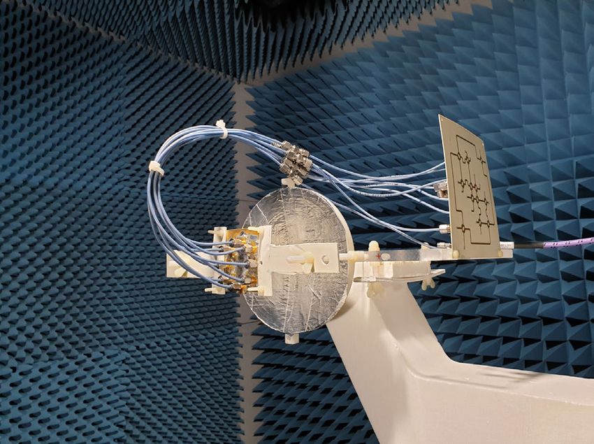
M. Haj Hassan et al.: Beam Divergence Reduction of Vortex Waves With a Tailored Lens and a Tailored Reflector

the following relation E(ρ, ϕ) = E0 (ρ)exp(jϕm)er , where                         Section II discusses the impact of the distance d between the
E0 (ρ) is the amplitude of the electric field strength, ϕ is the                  adjacent antenna elements on the radiation pattern. Whereas,
geometric azimuthal angle and m is the OAM mode order.                            the following Sections III and IV present the simulated and
There are many options to generate OAM waves such as ellip-                       the measured phase front, near- and far-field of the conven-
tical patch antennas (supporting two simultaneously excited                       tional and tailored lenses. Then, the same procedure is carried
orthogonally oriented resonant modes) [3], [4], uniform cir-                      out for the reflector with an OAM impressed source and
cular patch antenna arrays (UCA) [5], spiral phase plates [6],                    with realistic UCA in Sections V and VI. After that, Section
holographic plates [7], metasurfaces [8], and reflectors [9].                     VII introduces the measured gain and phase front of the
Each of these approaches have its advantages and disadvan-                        reflector. Finally, Section VIII concludes the findings of this
tages, regarding e.g. costs, fabrication simplicity, integration                  article.
capability, simple design and implementation, simple feeding
etc. The vortex waves contain unlimited number of mutu-                           II. DESIGN OF UNIFORM CIRCULAR ARRAY (UCA)
ally orthogonal mode orders m ∈ {. . . , −2, −1, 0, 1, 2, . . .}                  In the setup, a single rectangular patch antenna element
creating an additional degree of freedom in signal coding                         of 7.4 mm length (about λeff /2) and 10.8 mm width is
not to mention a new spatial division multiplexing (SDM).                         designed on a 30 mm × 30 mm printed circuit board (PCB).
This yields an independent data stream at the same operating                      Two insets in the antenna enable the matching of the antenna
frequency, thus an improvement in the capacity as well as                         to 50  so that the realized gain is maximized to 7 dBi. The
in the spectral efficiency. Moreover, a new physical trans-                       antenna is linearly polarized in the y-direction (according to
mission technique is earned by the OAM mode division                              the coordinate system given in Fig. 1 (a). In the following, this
multiplexing (OAM-MDM) which can be also combined to                              single antenna is extended to form a circular patch antenna
other types of multiplexing (time, polarization, frequency,                       array of 8 elements with a distance between the adjacent
and code). Such combination can lead to a large enhance-                          antennas of d = λ/2 (cf. Fig. 1 (b)) in order to obtain the
ment in the data transmission [10]. Additionally, the OAM                         desired optimized OAM waves characterized by a doughnut
waves are beneficial through increasing the digit value in the                    type radiation pattern, increased gain and lower side and back
RFID technology with the aid of helically arranged dielec-                        lobes. However, the slight asymmetry of the radiation pattern
tric resonator array instead of just one dielectric resonator.                    (cf. Fig. 1 (b)) is due to the single-sided, hence asymmetric
Otherwise, the conventional 0 and 1 digits are provided by                        feeding of each patch antenna element. As a result, this
the dielectric resonator [11]. In addition, it is also capable                    asymmetry is more noticeable for larger radii. The following
of rejecting the clutter coming from the broadside direction                      equations are representing the analytical expressions for the
 [12]. Furthermore, the vortex waves are beneficial for the                       electric field of the vortex waves in cylindrical coordinate
imaging of the fixed objects and can provide extra features                       system E(ρ, ϕ, z) propagating along the z-direction
for target localization where the Doppler effect is less com-
                                                                                                      Z0 ωm
plicated than the conventional radar application [13]. Nev-                                     Eρ = j       E0 Jl (kρ ρ)e−jkz z e−jmϕ ,        (1)
ertheless, the vortex waves are suffering from the strong                                               kρ
                                                                                                        Z0 ωkρ
beam divergence, especially when higher OAM mode orders                                         Eϕ = −         E0 Jl0 (kρ ρ)e−jkz z e−jmϕ ,     (2)
are needed [14]. This beam divergence can be an issue for                                                  k
many applications, like in the wireless communication and                                       Ez = 0,                                         (3)
in particular when using OAM beams in material character-                         where Z0 is the free-space wave impedance, ω is the angular
ization within advanced reflectometry schemes. As noticed,                        frequency, m is the OAM mode order, E0 is the wave ampli-
this beam divergence reduction is not performed to be used                        tude, Jl (kρ ρ) is the l th order Bessel function, k0 is the free-
in the MIMO application. Several publications have docu-                          space wave number
mented considerable efforts to reduce the beam divergence
by using Fabry-Perot Cavity [15], lenses, [16]–[19], antenna                                                             ω2
                                                                                                         k02 = kρ2 + kz2 =  ,                 (4)
arrays in UCA [20], and reflectors [9], [21]–[24]. Here, our                                                             c2
choice fell on the uniform circular patch antenna array (UCA)                     where c is the speed of light [27]. As noted, due to the
approach to be designed with a tailored lens and a tailored                       practical focus of the article, there is no need to discuss too
reflector to reduce the OAM beam divergence. These two                            much the theoretical part of the electric and magnetic field of
approaches can also be compared to the ones of metasur-                           the OAM waves. Furthermore, this study aims to reduce the
faces [8] and multi UCAs [25], where both methods support                         beam divergence in the broadside direction, i.e. the radiated
large effective apertures and thus reduced beam divergences.                      direction, where the gain of the main lobe would be increased.
The simulated and measured gain of the two approaches                             Moving on, the reflection coefficient S11 of the antennas is
are compared to those of the UCA, and to the conventional                         between −17 dB and −20 dB at the operating frequency of
lens and conventional reflector. The initial idea has been                        10 GHz, and the gain of the planar circular patch antenna
presented in an earlier paper, where a tailored lens is only                      array amounts to about 9.5 dBi for the OAM mode order
simulated and compared to cases including and excluding                           m = −1. Moreover, the footprint of the underlying PCB
the conventional one [26]. In the following, the proceeding                       board is 100 mm × 100 mm. The UCA is designed with the

VOLUME 9, 2021                                                                                                                                 9801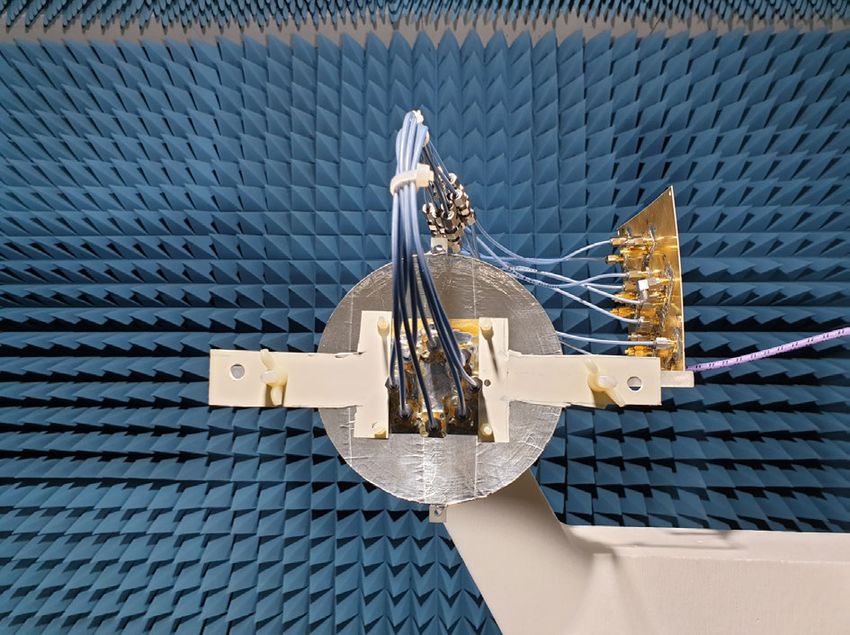
M. Haj Hassan et al.: Beam Divergence Reduction of Vortex Waves With a Tailored Lens and a Tailored Reflector

FIGURE 1. Top view of the UCA (a), the simulated radiation pattern (dBi)
of the UCA for the OAM mode order −1 at ϕ = 0◦ (H-plane) for an
element separation d of λ/2, 3λ/4, and λ (λ = 30 mm at 10 GHz) (b).

full-wave computational electromagnetics simulator FEKO
that processes the Method of Moments (MoM) generating a
high simulation efficiency for this setup. For a better man-
ageability, the operating frequency is set to 10 GHz. These
antennas are patterned on a Rogers RO4003C substrate with
a height of 1.524 mm and a relative permittivity of 3.55. The
phase shift between each pair of adjacent antennas is defined
by the port feeding phase in the full-wave simulator FEKO to                    FIGURE 2. Conventional lens (a, c, and e), and tailored lens (b, d, and f).
obtain the OAM mode with mode order m = −1. Thus, it is
defined by the following relation
                                                                                where a is the semi-minor axis of the ellipsoidal part along
                                 2πm
                            ϕ1 =     ,                                (5)       the z-axis, which depends on the target directivity in [dB],
                                  N                                             and b is the semi-major axis. L is signified as the length of
where N denotes the number of single antenna and m is the                       the extension part, and λ is the operating wavelength which
mode order of the vortex waves.                                                 happens to be 30 mm at 10 GHz. But, the equation (8) seems
                                                                                to assume an aperture efficiency of 100% which is most
III. DESIGN OF CONVENTIONAL AND TAILORED LENS
                                                                                probably false in the context of the presented OAM antennas.
In this section, the conventional lens and the tailored lens                    a is chosen to be 50 mm so that the assembly and the centering
are set up for comparison. Both of the two lenses are made                      of the lens on the PCB board are simplified, whereas the
of polypropylene with a 2.2 relative permittivity. However,                     radius of the UCA is 19.6 mm. Hence, L is 45.6 mm, and b is
the dielectric loading is causing an alteration in the effec-                   67.7 mm. On the other hand, the principle of Fermat permits
tive permittivity, thus the antennas need to be redesigned                      to design a lens for a single patch antenna [29]
accordingly. The new length and width of the patch antenna
element are 7.25 mm and 10.2 mm, respectively. Moreover,
the reflection coefficient S11 amounts to −37.6 dB for one                                                        r0 (n1 − n0 )
                                                                                                   r(ϑ) =                         ,                      (9)
patch antenna element at 10 GHz. As displayed in Fig. 2 (a),                                                     n1 − n0 cos(ϑ)
the conventional lens is divided into two parts, namely the                     where n1 is the refractive index of the lens with the value
cylindrical dielectric part and the ellipsoidal part. The cylin-                of 1.483, and n0 is the refractive index of the air with values
drical dielectric part shifts the focal point into the center of                of 1. The radius of the lens r(ϑ) relies on the polar angle
the UCA, while the ellipsoidal part converts the divergent                      ϑ, so r0 is the radius at the polar angle ϑ = 0◦ . The shape
spherical waves into a narrower beam. Therefore, the gain                       function (9) designs the tailored lens by means of sweeping
of the UCA is expected to increase, whereas the divergence                      this function which is shifted to align with the patch antenna’s
would correspondingly decrease. The design of the conven-                       center around the z-axis, as shown in Fig. 2 (b, d, and f). Sim-
tional lens uses the following equations [28] according to                      ilar to the conventional lens, the entire PCB board is covered
Fig. 2 (a, c, and e)                                                            to simplify the assembling of the lens with the UCA. Thus,
                                   a                                            the radius at the polar angle ϑ = 0◦ and ϑ = 90◦ are about
                       b= r                ,                 (6)
                                       1                                        93 mm and 30.4 mm, respectively. As r0 gets larger, the gain
                               1−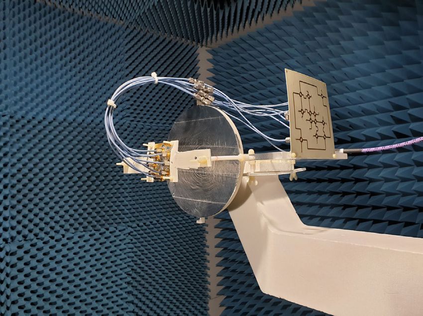
M. Haj Hassan et al.: Beam Divergence Reduction of Vortex Waves With a Tailored Lens and a Tailored Reflector

                                                                                  FIGURE 4. The simulated magnitude of the instantaneous electric field
FIGURE 3. The simulated radiation pattern (dBi) of UCA at ϕ = 0◦                  and the simulated phase distribution for the OAM mode order −1 of the
(H-plane) for the cases of without lens, with conventional lens and with          cases without lens (a, and d), with conventional lens (b, and e), and with
tailored lens for the OAM mode order 0 (a), −1 (b), and −2 (c).                   tailored lens (c, and f), respectively.

                                                                                  yielding a refraction of the waves in an undesirable direction.
to the decline of the gain and the beam divergence. In contrast,                  By increasing the aperture of the lens, the displacement error
the tailored lens (cf. Fig. 3 (b)) presents a significant decrease                decreases, and the issue would be minimized. This abnormal
in the beam divergence with a maximum gain showing a                              behavior of the conventional lens with the zeroth order mode
15.3 dBi value. Moreover, the number of side lobes is lower                       gives preference to the tailored lens over the conventional one
than the one in case of the conventional lens. The apertures                      especially when used in the OAM target localization where
of the two lenses are different, where the effective aperture                     several OAM mode orders are necessary to localize the target.
Ae , and the physical aperture Aphys are defined with [30]                        In Fig. 3 (c), once mode −2 is set, the two lenses yield similar
                                                                                  gain enhancements but with higher side lobe suppression
                                   λ2 G                                           levels with the tailored lens. Note that the maximum gain with
                               Ae =     ,                             (10)        the second mode order can be achieved with a distance d of
                                    4π
                           Aphys = πrmax
                                      2
                                          ,                           (11)        about λ between the adjacent antenna element (cf. Fig. 1 (a)).
                                     Ae                                           Therefore, the size difference between the conventional and
                             ea =         ,                           (12)        the tailored lens will be very large giving additional benefit
                                   Aphys
                                                                                  for the tailored lens. Fig. 4 introduces the instantaneous elec-
where λ is the wavelength in free space, and G signifies the                      tric field and the phase distribution of the OAM mode order
gain of the antenna. rmax is represented by a concerning the                      −1 of the cases without lens (a, and d), with conventional lens
conventional lens, while it is considered the maximum of                          (b, and e) and with tailored lens (c, and f).
r(ϑ) sin(ϑ) for the case of tailored lens (cf. Fig 2 (a, and b).
The ratio between the effective aperture and the physical one                     IV. LENS FABRICATION AND MEASUREMENTS
determines how effective an antenna can be upon receiving                         The designed conventional and tailored lens in the previous
electromagnetic waves. This ratio is called the aperture effi-                    section have been manufactured by an external company
ciency ea covering a range between 0 and 1. Considering                           with the help of a 3D printing machine. The measurement is
the conventional lens, its aperture efficiency is 0.12 unlike                     performed by a vector network analyzer (VNA) ZVA 40 from
the tailored lens which has 0.21 value. Thus, the tailored                        Rohde & Schwarz in an anechoic chamber hence avoiding
lens tends to be superior over the conventional. In Fig. 3 (a),                   unwanted reflections and distortions. A standard gain horn
the mode order 0 is depicted, but it is deformed by the                           antenna is utilized as a transmitter, whereas the assembled
conventional lens, while the tailored lens enhances the gain                      lens with the UCA and the Butler matrix (BM) are used
from 13.7 dBi to 19.5 dBi. This beam deformation of the                           as a receiver. The BM is the one responsible for generating
zeroth mode with the conventional lens occurs because of the                      the different OAM mode orders. The distance separating the
displacement of the antennas from the focal point of the lens                     transmitter and the receiver is about 5 m where the lens,

VOLUME 9, 2021                                                                                                                                         9803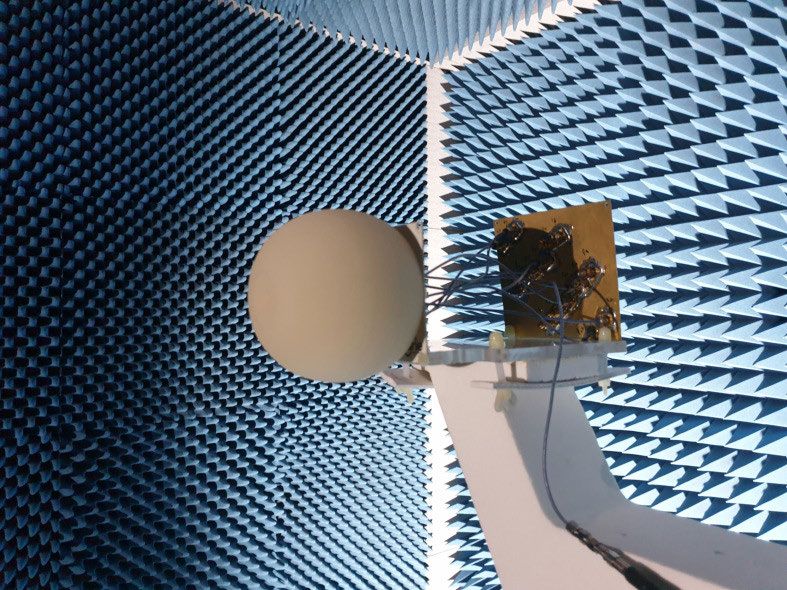
M. Haj Hassan et al.: Beam Divergence Reduction of Vortex Waves With a Tailored Lens and a Tailored Reflector
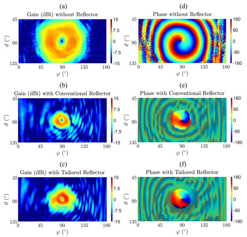
FIGURE 5. The rotary table in the anechoic chamber (a), the
manufactured UCA with Butler matrix (BM) (b), the conventional lens on
the UCA (c), and the tailored lens on the UCA (d).
FIGURE 7. Comparison between the measured gain (dBi) of the UCA at
ϑ = 0◦ (H-plane) without lens, with conventional lens, and with tailored
lens for the OAM mode order 1 (a), and 2 (b).
Meanwhile, in Fig. 6 (d, e, and f) the radiation possesses a
helical phase distribution of one helix according to the first
OAM mode order. An OAM mode of order m is characterized
by m number of helices in the phase front with a phase distri-
bution of α(ϕ) = mϕ noting that ϕ ranges between 0 and 2π.
Determining the positive OAM mode orders is done by the
right-handed thread with respect to the propagation direction
in which the vortex waves undergo clockwise rotation in
contrast to the negative modes rotating in a counter-clockwise
direction. Fig. 7 shows the measured gain in 2D (H -plane)
of the three cases for the OAM mode order 1 (a) and 2 (b).
Unlike the ideal case, it is noticeable that the gain in the center
FIGURE 6. The measured gain (dBi) and the measured phase distribution of the radiation pattern is not 0 (linear). This occurs due to
for the OAM mode order 1 of UCA without lens (a, and d), with several reasons such as the reflections in the BM and the
conventional lens (b, and e), and with tailored lens (c, and f).
misalignment between the transmitter and the receiver. And
with more observation, higher divergence is seen when the
OAM mode orders are raised.
accompanied by the UCA and the BM, are mounted on
a rotary table rotating in the azimuth angle ϕ from 0◦ to V. DESIGN OF CONVENTIONAL AND TAILORED
180◦ and in the elevation angle ϑ from 45◦ till 135◦ . The REFLECTOR WITH OAM IMPRESSED FIELD SOURCE
OAM mode order 1 is provided by the 8 × 8 BM which Likewise the lens, Fermat’s principle enables a conventional
is connected to the UCA by eight coaxial cables of equal reflector to be designed for a point source [29] characterized
length of 200 mm (cf. Fig. 5). Furthermore, the two lenses by r(ϑ) as a function of r0 and n1 . r(ϑ) denotes the radius
are assembled separately on the UCA (cf. Fig. 5 (c, and d)) to of the reflector hanging on the polar angle ϑ. On the second
be validated. Fig. 6 (a, b, and c) demonstrate the gain without hand, r0 is the radius at ϑ = 0◦ , whereas n1 is the refractive
lens, with conventional lens and with tailored lens, respec- index of the air with a value of 1.
tively. Compared to the others, the tailored lens achieved a
2r0
further superior performance by reducing the beam diver- r(ϑ) = . (13)
gence more. In addition, the gain is increased by 1.7 dBi n1 (1 + cos(ϑ))
to reach 9.7 dBi level regarding the conventional lens and The tailored reflector is achieved by sweeping the shape
by 4.8 dBi reaching 12.8 dBi in case of the tailored lens. function which has been shifted to align the patch antenna’s
9804 VOLUME 9, 2021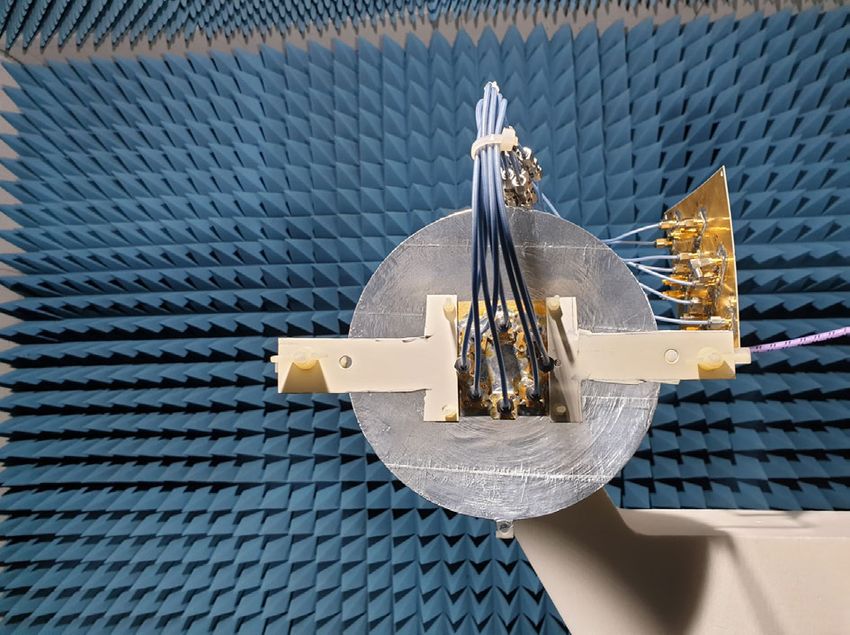
M. Haj Hassan et al.: Beam Divergence Reduction of Vortex Waves With a Tailored Lens and a Tailored Reflector

FIGURE 8. Reflector for a point source (a), extension to conventional             FIGURE 10. The simulated gain (dBi) for the OAM mode order −1
reflector (b), and extension to tailored reflector (c).                           depending on the angle ϑ with a height r0 of 90 mm using an OAM
                                                                                  impressed field source with conventional reflector and with tailored
                                                                                  reflector, and the aperture efficiency ea of the two reflectors.

FIGURE 9. The simulated gain (dBi) for the OAM mode order −1
depending on the height r0 of the reflector.

TABLE 1. The opening angle for the maximum simulated gain of each
reflectors (λ = 30 mm at 10 GHz) for the OAM mode order −1.

                                                                                  FIGURE 11. The simulated radiation pattern (dBi) using an OAM
                                                                                  impressed field source for the OAM mode order −1 with r0 of 40 mm and
                                                                                  with an angle ϑ from −90◦ till 90◦ without reflector, with conventional
                                                                                  reflector and with tailored reflector.

                                                                                  results are obtained without the impact of the ground plane
                                                                                  which may cause some reflections and diffractions of the
                                                                                  reflector radiation thus causing slight deviations in the com-
                                                                                  parison between the two reflectors. In Fig. 10, the comparison
                                                                                  between the two reflectors is undergone as a function of angle
center around the z-axis (13), as shown in Fig. 8 (a, b, and c).                  ϑ in which the tailored reflector shows better accomplishment
The two reflectors depend on two parameters, namely the                           until the angle reaches ϑ = 38◦ . In Fig. 11, the simulated
radius r and the angle ϑ. To be more specific, as the r and ϑ                     radiation pattern using an OAM impressed field source at ϕ =
get higher, the gain increases. Consequently, the divergence                      0◦ (H -plane) without reflector, with conventional reflector
of the vortex beams decreases due to the increased focusing                       and with tailored reflector are depicted seperately under
of the radiation pattern. And, the angle ϑ is adjusted from                       40 mm height and −90◦ till 90◦ ranged angle ϑ. The two
−90◦ till 90◦ . The tailored reflector will be compared to the                    reflectors reduce the divergence from about 9.5 dBi at angle
UCA with conventional reflector and to another one without                        336◦ to 13.2 dBi at angle 160◦ (conventional) and to 15.4 dBi
any reflector. The gain of the two reflectors is presented in                     at angle 170◦ (tailored). Unfortunately, the tailored reflector
Fig. 9 revealing that superior performance is achieved by                         causes a certain elevation of pattern due to the cut of the
the tailored reflector compared to the conventional reflector                     reflector in the middle allowing some rays to propagate into
especially with the height of 1.5λ. Despite that there is no big                  the second part of the reflector whereby undesired reflections
gain difference between the two reflectors beyond 1.5λ, the                       can occur (cf. Fig 11). Whenever the UCA radius is larger or
tailored reflector continues to administrate a higher reduction                   the height r0 is lower, a decline of the elevation will occur.
in the divergence because the maximum gain is even closer                         In Figs. 12 and 13, the instantaneous electric field and the
to the broadside radiation (cf. table 1). Note that these gain                    helical phase front of the three cases are depicted. Generally,

VOLUME 9, 2021                                                                                                                                           9805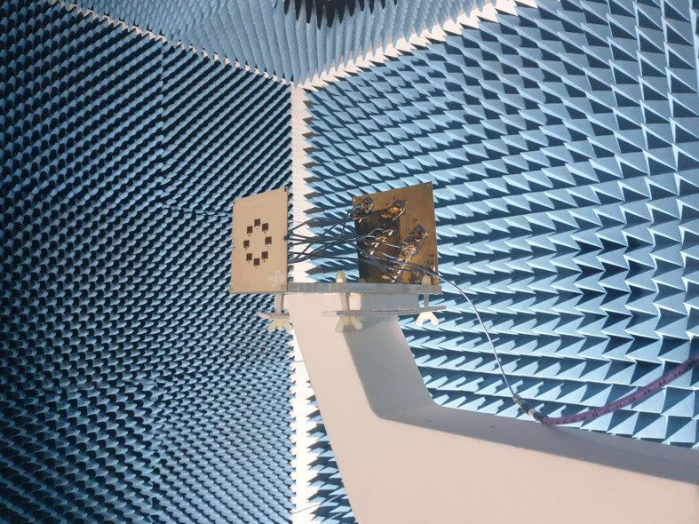
M. Haj Hassan et al.: Beam Divergence Reduction of Vortex Waves With a Tailored Lens and a Tailored Reflector

FIGURE 12. The simulated magnitude of the instantaneous electric field
using an OAM impressed field source for the OAM mode order −1 with r0
of 40 mm and with an angle ϑ from −90◦ till 90◦ without reflector (a),
with conventional reflector (b) and with tailored reflector (c).

FIGURE 13. The simulated phase distribution of Ey using an OAM
impressed field source for the OAM mode order −1 (from x = −300 till
300 mm, from y = −300 till 300 mm, z = 300 mm for (a) and
z = −300 mm for (b, and c)) indicating the phase distribution of OAM            FIGURE 14. The simulated gain (dBi) of the realistic UCA for the OAM
impressed field source with r0 of 40 mm and with an angle ϑ from −90◦           mode order −1 depending on the height r0 of the reflector with a 60 mm
till 90◦ without reflector (a), with conventional reflector (b) and with        diameter circular ground plane (a), for a 60 mm × 60 mm rectangular
tailored reflector (c).                                                         ground plane (b) and for a 100 mm × 100 mm rectangular ground
                                                                                plane (c).

the OAM mode order is inverted after the reflection with the                    Figs. 16 and 17 display the radiation pattern for the OAM
reflectors, namely +1 instead of −1.                                            mode order −1 of the two reflectors in 2D at ϕ = 0◦
                                                                                (H -plane) for heights r0 of 30 mm, 51 mm, and 120 mm. As
VI. REFLECTOR EVALUATION INCLUDING REALISTIC                                    shown, the tailored reflector performs well with the height
FEEDING ANTENNA STRUCTURE                                                       r0 of λ unlike the conventional reflector which reveals a
In the prior section, the three cases are presented using an                    distinctly shaped OAM beam with the height r0 of 1.67λ.
OAM impressed field source to simplify the interpretation                       In Figs. 18 and 19, the instantaneous electric field and the
of the reflector’s behavior. While in this section, the reflec-                 phase distribution of the (60 mm×60 mm) rectangular shaped
tors are simulated with a realistic UCA mounted on three                        UCA for the OAM mode order −1 with 40 mm height r0
different shaped ground planes. The first shape is a circular                   and with an angle ϑ from −90◦ till 90◦ are introduced. The
PCB with a diameter of 60 mm, whereas the second and the                        helicity of the front phase is still maintained but with opposite
third shapes consists of a rectangular PCB with a footprint                     OAM mode order’s sign, namely from the mode −1 to the
of 60 mm × 60 mm and 100 mm × 100 mm, respectively.                             mode 1, and with higher distortion for the conventional reflec-
Fig. 14 establishes the gain according to the height r0 in                      tor. Fig. 20 shows the radiation pattern of the OAM mode
an angle ϑ ranging from −90◦ till 90◦ in which the gain                         orders 0, −1 and −2 with a height of 90 mm and an angle
oscillation is caused by the ground plane due to the standing                   ϑ of 45◦ . In the case of the zeroth mode order, the tailored
waves between the UCA and the reflector. The three different                    reflector increases the gain from 13.9 dBi to 19.6 dBi in
shaped ground planes manipulate the gain of the conventional                    contrast to the conventional reflector that decreases the gain
reflector more than the tailored one. In Fig. 15, the gain                      till 10.3 dBi. This is noted as a similar behavior to that of the
based on the angle ϑ with a height r0 of 90 mm is depicted.                     conventional lens compared to the tailored lens. With respect
The circular ground plane shape has minimal effect on the                       to the first OAM mode order, the gain of the conventional
gain of the reflectors giving it the priority for the reflectors.               and tailored reflector is increased from about 9.5 dBi till

9806                                                                                                                                         VOLUME 9, 2021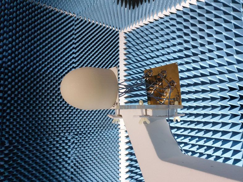
M. Haj Hassan et al.: Beam Divergence Reduction of Vortex Waves With a Tailored Lens and a Tailored Reflector

                                                                                  FIGURE 16. The simulated radiation pattern (dBi) with realistic UCA for
                                                                                  the OAM mode order −1 of conventional reflector of UCA with a
                                                                                  rectangular shaped PCB 60 mm × 60 mm for several height r0 of 30 mm,
                                                                                  51 mm, and 120 mm.

FIGURE 15. The simulated gain (dBi) of the realistic UCA for the OAM
mode order −1 depending on the angle ϑ of the reflector for the mode
order −1 with a height r0 of 90 mm with a 60 mm diameter circular
ground plane (a), for a 60 mm × 60 mm rectangular ground plane (b) and
for a 100 mm × 100 mm rectangular ground plane (c).

16.5 dBi and 17.8 dBi, respectively. The tailored reflector
yields 1.3 dBi more than the conventional reflector. While for
the second OAM mode order, the gain of the conventional and
the tailored reflector is increased from 6.3 dBi till 10.4 dBi
and 13.9 dBi, respectively. Once the mode orders increase,
the gain decreases because of the raised divergence. Similar
to the tailored lens, the tailored reflector offers a benefit                     FIGURE 17. The simulated radiation pattern (dBi) with realistic UCA for
                                                                                  the OAM mode order −1 of tailored reflector of UCA with a rectangular
of saving material consumption especially for larger UCA                          shaped form 60 mm × 60 mm for several height r0 of 30 mm, 51 mm, and
radii in addition to extra antenna elements. Noting that the                      120 mm.

production and the equipment are limited, a reflector with a
height of 90 mm and an angle of 45◦ is chosen.                                    divergence of the OAM mode order 1 is obviously reduced.
                                                                                  The tailored reflector submits values of 12 dB as measured
VII. REFLECTOR FABRICATION AND MEASUREMENTS                                       and 17.8 dB as simulated. Whereas 10.5 dB measured gain
In the same manner as the lens, a conventional reflector and                      and 16.5 dB simulated one are revealed with the conventional
a tailored reflector with a height of 90 mm and an open-                          one (cf. Fig. 23 (a)). As noticed, there is a variation between
ing angle ϑ of 45◦ are manufactured using a 3D printing                           the measured and simulated values. This is due to the pro-
machine to be measured in the anechoic chamber over a                             ceeding mentioned issues. First of all, the reflectors are not
rotating stage. The reflectors consist of polypropylene which                     completely smooth due to the 3D printing method. On the
should be covered with aluminium foil in order to behave                          second hand, the aluminium layers are not perfectly bonded to
like a reflector. The reflector is assembled with the UCA and                     the UCA, and the antennas are fixed with a plastic patch that
with the BM as shown in (cf. Fig 21). In Fig. 22, the beam                        creates a certain absorption and delay of the reflected vortex

VOLUME 9, 2021                                                                                                                                       9807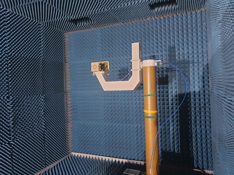
M. Haj Hassan et al.: Beam Divergence Reduction of Vortex Waves With a Tailored Lens and a Tailored Reflector

FIGURE 18. The simulated magnitude of the instantaneous electric field
with a realistic UCA for the OAM mode order −1 of the circular antenna
array with rectangular shaped PCB 60 mm × 60 mm without reflector (a),
with conventional reflector (b), and with tailored reflector (c).

                                                                                FIGURE 21. The manufactured conventional reflector (a, and c), and
                                                                                tailored reflector (b, and d).

FIGURE 19. The simulated phase distribution of Ey with a realistic UCA
for the OAM mode order −1 with rectangular shaped PCB
60 mm × 60 mm (from x = −300 till 300 mm, from y = −300 till 300 mm,
z = 300 mm for (a) and z = −300 mm for (b, and c)) indicating the helical
phase distribution of circular antenna array without and with reflector.

                                                                                FIGURE 22. The measured gain (dBi) and the measured phase
                                                                                distribution of antennas for the OAM mode order 1 without reflector
                                                                                (a, and d), with conventional reflector (b, and e), and with tailored
                                                                                reflector (c, and f) with rectangular ground plane shape 60 mm × 60 mm
                                                                                (height of 90 mm and angle of 45◦ ).

                                                                                eight coaxial cables which can interfere with the path of the
                                                                                vortex waves. Nonetheless, in order to avoid such issues,
                                                                                the BM or the power divider (PD) [31] can be integrated
                                                                                into the ground plane, otherwise two reflectors (primary and
                                                                                secondary) such as the Cassegrain reflector can be applied.
                                                                                The phase distribution of the three cases which displays a
                                                                                distinct helical phase distribution of the first OAM mode
                                                                                order are also presented in the figure 22. Note that aiming
                                                                                for the helical phase distribution in the doughnut radiation
FIGURE 20. The simulated radiation pattern (dBi) with a realistic UCA for
the three cases for the OAM mode order 0 (a), −1 (b), and −2 (c) at             pattern is purposed. Fig. 23 shows the gain for the OAM mode
ϕ = 0◦ (H-plane) with a height of 90 mm and an angle of 45◦ .                   order 1 and 2 at ϕ = 0◦ (H -plane). The measured gain of
                                                                                OAM mode order 2 (7.7 dBi) administers a gain enhancement
waves. Therefore, the UCA and the reflector are not perfectly                   of 4.5 dB and 3.1 dB compared to the UCA without reflector
in alignment. Furthermore, the antennas are supplied with                       and with conventional reflector, respectively (cf. Fig. 23 (b)).

9808                                                                                                                                         VOLUME 9, 2021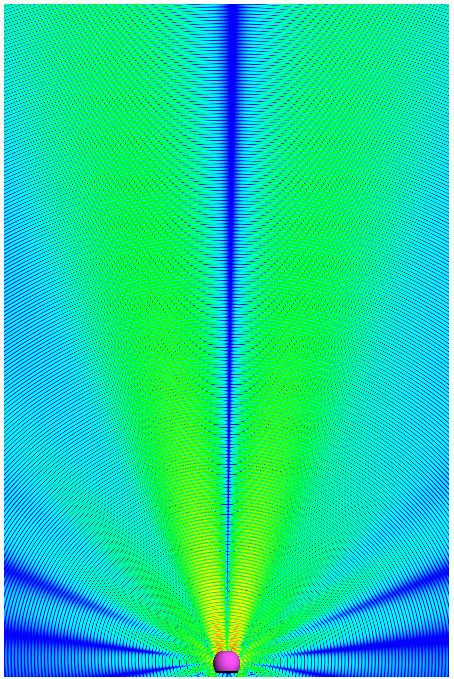
M. Haj Hassan et al.: Beam Divergence Reduction of Vortex Waves With a Tailored Lens and a Tailored Reflector

                                                                                  needed for applications such as the target localization with
                                                                                  vortex waves.
                                                                                  REFERENCES
                                                                                   [1] L. Allen, M. W. Beijersbergen, R. J. C. Spreeuw, and J. P. Woerdman,
                                                                                       ‘‘Orbital angular momentum of light and the transformation of Laguerre–
                                                                                       Gaussian laser modes,’’ Phys. Rev. A, Gen. Phys., vol. 45, no. 11,
                                                                                       pp. 8185–8189, Jun. 1992.
                                                                                   [2] C. Zhang and L. Ma, ‘‘Millimetre wave with rotational orbital angular
                                                                                       momentum,’’ Sci. Rep., vol. 6, no. 1, pp. 1–8, Sep. 2016.
                                                                                   [3] J. J. Chen, Q. N. Lu, F. F. Dong, J. J. Yang, and M. Huang, ‘‘Wireless
                                                                                       OAM transmission system based on elliptical microstrip patch antenna,’’
                                                                                       Opt. Exp., vol. 24, no. 11, pp. 11531–11538, May 2016.
                                                                                   [4] M. Barbuto, M.-A. Miri, A. Alu, F. Bilotti, and A. Toscano, ‘‘A topological
                                                                                       design tool for the synthesis of antenna radiation patterns,’’ IEEE Trans.
                                                                                       Antennas Propag., vol. 68, no. 3, pp. 1851–1859, Mar. 2020.
                                                                                   [5] Q. Bai, A. Tennant, B. Allen, and M. U. Rehman, ‘‘Generation of orbital
                                                                                       angular momentum (OAM) radio beams with phased patch array,’’ in Proc.
                                                                                       Loughborough Antennas Propag. Conf. (LAPC). Loughborough, U.K.:
                                                                                       IEEE, Nov. 2013, pp. 410–413.
                                                                                   [6] P. Schemmel, G. Pisano, and B. Maffei, ‘‘Modular spiral phase plate design
                                                                                       for orbital angular momentum generation at millimetre wavelengths,’’ Opt.
                                                                                       Exp., vol. 22, no. 12, pp. 14712–14726, Jun. 2014.
                                                                                   [7] F. E. Mahmouli and S. D. Walker, ‘‘4-Gbps uncompressed video transmis-
                                                                                       sion over a 60-GHz orbital angular momentum wireless channel,’’ IEEE
                                                                                       Wireless Commun. Lett., vol. 2, no. 2, pp. 223–226, Apr. 2013.
                                                                                   [8] F. Qin, L. Wan, L. Li, H. Zhang, G. Wei, and S. Gao, ‘‘A transmission meta-
                                                                                       surface for generating OAM beams,’’ IEEE Antennas Wireless Propag.
FIGURE 23. The measured gain (dBi) comparison between UCA without                      Lett., vol. 17, no. 10, pp. 1793–1796, Oct. 2018.
reflector, with conventional reflector, and with tailored reflector with           [9] T. Nguyen, R. Zenkyu, M. Hirabe, T. Maru, and E. Sasaki, ‘‘A study of
rectangular ground plane shape 60 mm × 60 mm (height of 90 mm and                      orbital angular momentum generated by parabolic reflector with circular
angle of 45◦ ) at ϕ = 0◦ (H-plane) for the OAM mode order 1 (a), and 2 (b).
                                                                                       array feed,’’ in Proc. Int. Symp. Antennas Propag. (ISAP). Okinawa, Japan:
                                                                                       IEEE, 2016, pp. 708–709.
                                                                                  [10] W. Zhang, S. Zheng, X. Hui, R. Dong, X. Jin, H. Chi, and X. Zhang, ‘‘Mode
                                                                                       division multiplexing communication using microwave orbital angular
VIII. CONCLUSION                                                                       momentum: An experimental study,’’ IEEE Trans. Wireless Commun.,
In this article, a novel lens and reflector are designed for                           vol. 16, no. 2, pp. 1308–1318, Feb. 2017.
OAM waves in order to overcome the large beam divergence                          [11] M. H. Hassan, A. A. Abbas, A. Jimenez-Saez, A. M. Ahmad, B. Sievert,
                                                                                       M. Schussler, A. Rennings, K. Solbach, T. Kaiser, R. Jakoby, A. Sezgin,
inherent to OAM waves which are generated by uniform                                   and D. Erni, ‘‘Passive orbital angular momentum RFID tag based on
circular patch array (UCA) at 10 GHz. Both the tailored lens                           dielectric resonator arrays,’’ in Proc. 3rd Int. Workshop Mobile THz Syst.
and the tailored reflector are compared to the conventional                            (IWMTS), Essen, Germany, Jul. 2020, pp. 1–4.
                                                                                  [12] M. H. Hassan, B. Sievert, J. T. Svejda, A. A. Abbas, A. Jimenez-Saez,
ones demonstrating better simulated and measured gain. Par-                            A. M. Ahmad, M. Schubler, A. Rennings, K. Solbach, T. Kaiser, R. Jakoby,
ticularly, the tailored lens with a height r0 of 93 mm has                             A. Sezgin, and D. Erni, ‘‘OAM mode order conversion and clutter rejection
                                                                                       with OAM-coded RFID tags,’’ IEEE Access, vol. 8, pp. 218729–218738,
a simulated gain enhancement of 5.8 dB and 4.8 dB of                                   2020.
measured gain for the first OAM mode order compared to                            [13] K. Liu, X. Li, Y. Gao, H. Wang, and Y. Cheng, ‘‘Microwave imaging of
the gain of a UCA without lens. Concerning the conventional                            spinning object using orbital angular momentum,’’ J. Appl. Phys., vol. 122,
                                                                                       no. 12, Sep. 2017, Art. no. 124903.
lens, it provides a 1.8 dB simulated gain enhancement and                         [14] M. J. Padgett, F. M. Miatto, M. P. J. Lavery, A. Zeilinger, and R. W. Boyd,
1.7 dB measured one. Furthermore, the improved gain of                                 ‘‘Divergence of an orbital-angular-momentum-carrying beam upon prop-
the tailored reflector reveals that it is more effective than                          agation,’’ New J. Phys., vol. 17, no. 2, Feb. 2015, Art. no. 023011.
                                                                                  [15] X. Bai, Y. Sun, P. Hu, J. Chen, W. Yan, X. Liang, C. He, J. Geng,
the conventional one until it reaches a height r0 of 1.5λ                              and R. Jin, ‘‘Improvement on the multi-mode beams divergence of oam
and an angle ϑ of 38◦ , separately. A tailored reflector fed                           array by using Fabry–Perot cavity,’’ in Proc. IEEE Int. Symp. Antennas
by a UCA on rectangular ground plane (60 mm × 60 mm)                                   Propag. USNC/URSI Nat. Radio Sci. Meeting. San Diego, CA, USA: IEEE,
                                                                                       Jul. 2017, pp. 2193–2194.
with a height r0 of 90 mm and an angle ϑ of 45◦ has a                             [16] H. Fukumoto, H. Sasaki, D. Lee, and T. Nakagawa, ‘‘Beam divergence
simulated gain improvement of 8.3 dBi and measured one                                 reduction using dielectric lens for orbital angular momentum wireless
                                                                                       communications,’’ in Proc. Int. Symp. Antennas Propag. (ISAP). Okinawa,
of 3.9 dB for the first OAM mode order compared to the
                                                                                       Japan: IEEE, Oct. 2016, pp. 680–681.
gain of a UCA without reflector. Whereas the conventional                         [17] Y. Yao, X. Liang, W. Zhu, J. Li, J. Geng, R. Jin, and K. Zhuang, ‘‘Real-
reflector has a 7 dB simulated gain enhancement and 2.5 dB                             izing orbital angular momentum (OAM) beam with small divergence
                                                                                       angle by luneberg lens,’’ in Proc. IEEE Int. Symp. Antennas Propag.
measured one. Moreover, the tailored lens and reflector have                           USNC/URSI Nat. Radio Sci. Meeting. San Diego, CA, USA: IEEE,
a further advantage over the conventional ones through saving                          Jul. 2017, pp. 367–368.
material consumption. This interest appears more obvious                          [18] Y. Yao, X. Liang, W. Zhu, J. Geng, and R. Jin, ‘‘Synthesizing orbital
                                                                                       angular momentum beam with small divergence angle,’’ in Proc. 6th Asia–
when higher OAM mode orders are applied with the aid of                                Pacific Conf. Antennas Propag. (APCAP), Xi’an, China: IEEE, Oct. 2017,
extra widely separated antennas. As a summary, this study                              pp. 1–3.
demonstrates that the vortex waves need a tailored lens or a                      [19] Z. Shi, Y. Jianjia, X. Cao, R. Feng, H. Zhang, and S. N. Burokur, ‘‘Omni-
                                                                                       directional radiation lens design of vortex beam carrying orbital angular
tailored reflector to decrease the beam divergence effectively                         momentum based on spatial transformation,’’ in Proc. 13th Eur. Conf.
as a function of all OAM mode orders which is necessarily                              Antennas Propag. (EuCAP). Krakow, Poland: IEEE, 2019, pp. 1–4.

VOLUME 9, 2021                                                                                                                                              9809
M. Haj Hassan et al.: Beam Divergence Reduction of Vortex Waves With a Tailored Lens and a Tailored Reflector
[20] M. H. Hassan, M. Al-Mulla, B. Sievert, A. Rennings, and D. Erni, ‘‘Eval- JAN TARO SVEJDA (Member, IEEE) received
uation of different phased array approaches for orbital angular momen- the B.Sc. degree in electrical engineering from the
tum beam steering,’’ in Proc. German Microw. Conf. (GeMiC). Cottbus, University of Applied Science, Düsseldorf, Ger-
Germany: IEEE, 2020, pp. 44–47. many, in 2008, and the M.Sc. and Dr.Ing. degrees
[21] J. Y. Hong, W. Lee, B.-S. Kim, M.-S. Kang, J.-B. Kim, W. J. Byun, in electrical engineering and information technol-
and M. S. Song, ‘‘Use of tractroid factor in deformed parabolic reflector ogy from the University of Duisburg-Essen, Duis-
antenna which transfers orbital angular momentum modes,’’ in Proc. Int.
burg, Germany, in 2013 and 2019, respectively,
Conf. Inf. Commun. Technol. Converg. (ICTC), 2017, pp. 1229–1231.
[22] W. Byun, Y. Lee, B. S. Kim, K. S. Kim, M. S. Kang, and Y. H. Cho, for his research work in the field of X-nuclei
‘‘Simple generation of orbital angular momentum modes with azimuthally based magnetic resonance imaging. He is cur-
deformed Cassegrain subreflector,’’ Electron. Lett., vol. 51, no. 19, rently working as a Research Assistant with the
pp. 1480–1482, Sep. 2015. Department of General and Theoretical Electrical Engineering, University
[23] W. J. Byun and Y. H. Cho, ‘‘Generation of an orbital angular momentum of Duisburg-Essen, where he is involved in teaching several lectures and
mode based on a Cassegrain reflectarray antenna,’’ in Proc. IEEE Int. courses mainly in the field of electrical engineering. His general research
Symp. Antennas Propag. USNC/URSI Nat. Radio Sci. Meeting, Jul. 2017, interests include the all aspects of theoretical and applied electromagnetics,
pp. 1191–1192. currently focusing on medical applications, electromagnetic metamaterials,
[24] F. Qin, J. Yi, W. Cheng, Y. Liu, H. Zhang, and S. Gao, ‘‘A high-gain shared- and scientific computing methods.
aperture dual-band OAM antenna with parabolic reflector,’’ in Proc. 12th
Eur. Conf. Antennas Propag. (EuCAP). London, U.K.: EuCAP, 2018, pp.
1–4, doi: 10.1049/cp.2018.0685.
[25] F. Qin, L. Li, Y. Liu, W. Cheng, and H. Zhang, ‘‘A four-mode OAM antenna
array with equal divergence angle,’’ IEEE Antennas Wireless Propag. Lett.,
vol. 18, no. 9, pp. 1941–1945, Sep. 2019. AYA MOSTAFA AHMED received the B.Sc.
[26] M. H. Hassan, B. Sievert, A. Rennings, and D. Erni, ‘‘Reducing the
and M.Sc. degrees in electrical engineering from
divergence of vortex waves with a lens tailored to the utilized circular
antenna array,’’ in Proc. 2nd Int. Workshop Mobile THz Syst. (IWMTS),
German University, Cairo, Egypt, in 2011 and
Bad Neuenahr, Germany, Jul. 2019, pp. 1–4. 2014, respectively. She is currently pursuing the
[27] K. Liu, Y. Gao, X. Li, and Y. Cheng, ‘‘Target scattering characteristics for Ph.D. degree with the Institute of Digital Com-
OAM-based radar,’’ AIP Adv., vol. 8, no. 2, Feb. 2018, Art. no. 025002. munication Systems, Ruhr-Universität Bochum,
[28] A. Bisognin, N. Nachabe, C. Luxey, F. Gianesello, D. Gloria, J. R. Costa, Germany. Her research interests include MIMO
C. A. Fernandes, Y. Alvarez, A. Arboleya-Arboleya, J. Laviada, radar signal processing, waveform design opti-
F. Las-Heras, N. Dolatsha, B. Grave, M. Sawaby, and A. Arbabian, ‘‘Ball mization, cognitive radars, direction of arrival
grid array module with integrated shaped lens for 5G backhaul/fronthaul (DOA) algorithms, and machine learning applica-
communications in F-band,’’ IEEE Trans. Antennas Propag., vol. 65, tions for radar resources management.
no. 12, pp. 6380–6394, Dec. 2017.
[29] J. Thornton and K.-C. Huang, Modern Lens Antennas for Communications
Engineering, vol. 39. Hoboken, NJ, USA: Wiley, 2013.
[30] C. A. Balanis, Antenna Theory: Analysis and Design. Hoboken, NJ, USA:
Wiley, 2016.
[31] L. Weisgerber and A. E. Popugaev, ‘‘Multibeam antenna array for RFID
JAN BAROWSKI (Senior Member, IEEE) was
applications,’’ in Proc. Eur. Microw. Conf., 2013, pp. 84–87.
born in Bochum, Germany, in 1988. He received
the B.Sc., M.Sc., and Dr.Ing. degrees in electri-
cal engineering from Ruhr-University Bochum,
Bochum, in 2010, 2012, and 2017, respectively.
MOHAMED HAJ HASSAN was born in Beirut, Since 2012, he has been with the Institute of
Lebanon. He received the B.Sc. degree in electrical Microwave Systems, headed by Ilona Rolfes,
engineering and the M.Sc. degree in high- Ruhr-University Bochum, as a Research Assis-
frequency technology from the Technical Univer- tant. He is currently working as a Postdoctoral
sity of Berlin, Berlin, Germany, in 2010 and 2012, Research Scientist with the Institute of Microwave
respectively. He has worked as an RF Specialist Systems, Ruhr-University Bochum. His research interests include radar sig-
in the industry for about two years. From 2015 nal processing, radar imaging, and material characterization techniques.
to 2017, he was with the Technical University of
Ilmenau, Ilmenau, Germany, in the field of ground
penetration radar (GPR). Since 2017, he has a
member with the Laboratory of General and Theoretical Electrical Engi-
neering, University of Duisburg-Essen. His research interests include RF and
ANDREAS RENNINGS (Member, IEEE) received
antenna technology, mm-waves, vortex waves, electromagnetic metamateri-
the Dipl.Ing. and Dr.Ing. degrees from the Uni-
als, and computational electromagnetics.
versity of Duisburg-Essen, Germany, in 2000 and
2008, respectively. He studied electrical engineer-
ing at the University of Duisburg-Essen. He carried
out his diploma work during a stay at the Univer-
BENEDIKT SIEVERT (Member, IEEE) was born sity of California at Los Angeles. From 2006 to
in Krefeld, Germany. He received the B.Sc. 2008, he was with IMST GmbH, Kamp-Lintfort,
and M.Sc. degrees in electrical engineering/high- Germany, where he has worked as an RF Engineer.
frequency systems from the University of Since then, he has been the Senior Scientist and
Duisburg-Essen, in 2017 and 2019, respectively. a Principal Investigator with the Laboratory for General and Theoretical
Since 2017, he has been a member with the Electrical Engineering, University of Duisburg-Essen. His general research
Laboratory of General and Theoretical Electri- interests include all aspects of theoretical and applied electromagnetics,
cal Engineering, University of Duisburg-Essen. currently with a focus on medical applications and on-chip millimeter-
His research interests include mm-wave on-chip wave/THz antennas. He received several awards, including the Student Paper
antennas, electromagnetic metamaterials, and the- Price at the 2005 IEEE Antennas and Propagation Society International
oretical and computational electromagnetics. Symposium and the VDE-Promotionspreis 2009 for the dissertation.
9810 VOLUME 9, 2021M. Haj Hassan et al.: Beam Divergence Reduction of Vortex Waves With a Tailored Lens and a Tailored Reflector
ILONA ROLFES (Member, IEEE) received the DANIEL ERNI (Member, IEEE) received the
Dipl.Ing. and Dr.Ing. degrees in electrical engi- Diploma degree in electrical engineering from
neering from Ruhr University Bochum, Bochum, the University of Applied Sciences Rapperswil
Germany, in 1997 and 2002, respectively. From (HSR), in 1986, the Diploma degree in electrical
1997 to 2005, she was with the High Frequency engineering from ETH Zürich, in 1990, and the
Measurements Research Group, Ruhr University Ph.D. degree in laser physics from the Labora-
Bochum, as a Research Assistant. From 2005 to tory for Electromagnetic Fields and Microwave
2009, she was a Junior Professor with the Depart- Electronics, ETH Zürich, in 1996. Since 1990, he
ment of Electrical Engineering, Leibniz University has been working with the Laboratory for Electro-
Hannover, Hannover, Germany, where she became magnetic Fields and Microwave Electronics, ETH
the Head of the Institute of Radio frequency and Microwave Engineering in Zürich. From 1995 to 2006, he was the Founder and the Head of the
2006. Since 2010, she has been leading the Institute of Microwave Systems, Communication Photonics Group, ETH Zürich. Since October 2006, he has
Ruhr University Bochum. Her research interests include high-frequency been a Full Professor of general and theoretical electrical engineering with
measurement methods for vector network analysis, material characterization, the University of Duisburg-Essen, Germany. His current research interests
noise characterization of microwave devices, sensor principles for radar include optical interconnects, nanophotonics, plasmonics, advanced solar
systems, and wireless solutions for communication systems. cell concepts, optical and electromagnetic metamaterials, RF, mm-wave and
THz engineering, biomedical engineering, bioelectromagnetics, marine elec-
tromagnetics, computational electromagnetics, multiscale and multiphysics
AYDIN SEZGIN (Senior Member, IEEE) received
modeling, numerical structural optimization, and science and technology
the M.S. degree in communications engineering
studies (STS). He is a member of the Center for Nanointegration Duisburg-
from Technische Fachhochschule Berlin (TFH),
Essen (CeNIDE). He is the Co-Founder of the spin-off company airCode on
Berlin, in 2000, and the Ph.D. degree in electrical
flexible printed RFID technology. He is a Fellow of the Electromagnetics
engineering from TU Berlin, in 2005. From 2001
Academy and a member of the Swiss Physical Society (SPS), the German
to 2006, he was with the Heinrich-Hertz-Institut,
Physical Society (DPG), and the Optical Society of America (OSA).
Berlin. From 2006 to 2008, he held a postdoctoral
position, and was also a Lecturer with the Infor-
mation Systems Laboratory, Department of Elec-
trical Engineering, Stanford University, Stanford,
CA, USA. From 2008 to 2009, he held a postdoctoral position with the
Department of Electrical Engineering and Computer Science, University of
California at Irvine, Irvine, CA, USA. From 2009 to 2011, he was the Head of
the Emmy-Noether Research Group on Wireless Networks, Ulm University.
In 2011, he joined TU Darmstadt, Germany, as a Professor. He is currently a
Professor of information systems and sciences with the Department of Elec-
trical Engineering and Information Technology, Ruhr-Universität Bochum,
Germany. His research interests include signal processing, communication,
and information theory, with a focus on wireless networks. He has published
several book chapters more than 40 journals and 140 conference papers in
these topics. He has coauthored a book on multiway communications. He is
a winner of the ITG-Sponsorship Award, in 2006. He was a first recipient of
the prestigious Emmy-Noether Grant by the German Research Foundation in
communication engineering, in 2009. He has coauthored papers that received
the Best Poster Award at the IEEE Communication Theory Workshop in
2011, the Best Paper Award at ICCSPA in 2015, and the Best Paper Award at
ICC in 2019. He has served as an Associate Editor for the IEEE TRANSACTIONS
ON WIRELESS COMMUNICATIONS from 2009 to 2014.
VOLUME 9, 2021 9811You can also read