Bidirectional Hybrid HVDC CB with a single HV Valve
←
→
Page content transcription
If your browser does not render page correctly, please read the page content below
1
Bidirectional Hybrid HVDC CB with a single
HV Valve
Dragan Jovcic, Senior Member, IEEE, Mario Zaja, Student Member, IEEE and Mohammad
Hedayati, Member, IEEE
product. The performance requirements for each project will
Abstract – This paper examines two new bidirectional hybrid specify if unidirectional or bidirectional HCB is needed.
dc circuit breaker topologies for application in meshed dc grids. Reference [11] presents slightly different HCB based on full-
The goal is to retain performance of hybrid DC CB with bridge cells in the main valve, which has bidirectional
bidirectional current interruption, while reducing semiconductor interruption capability. Unidirectional version could be
count, DC CB size and weight. The fault current is routed to the developed using less-expensive half-bridge cells.
unidirectional internal valve using multiple additional ultrafast
Reference [12] recognizes that there is potentially significant
disconnectors. Operation of both topologies is studied using a 320
kV, 16 kA simulation model, as well as demonstrated on a 900 V, cost saving if a unidirectional main valve is used. It proposes a
500 A lab prototype. The control systems are presented and new bidirectional HCB where the main branch consists of a
discussed in detail. The low-voltage hardware prototypes verify single HV IGBT valve and 4 HV diode valves under the
performance of several new technical and operating solutions in assumption that diode valve is considerably less expensive and
laboratory conditions. A comparison is made with the existing DC has better reliability than IGBT valve. Nevertheless this HCB
CB topologies and performance and reliability compromises of requires 4 diode valves rated for line voltage which will have
each topology are assessed. The conclusion is that it might be substantial size and weight despite its presumed lower cost.
possible to halve the DC CB semiconductor count while retaining The high-cost (bidirectional) main breaker branch of HCB
same 2 ms opening speed and bidirectional operation.
can be shared between two HCBs on two nearby lines in a DC
substation as it is analyzed in [13].
Index Terms-- DC meshed grids, HVDC protection, HCB, fault
current limiting. Driven by the potential for significant HCB simplification,
this paper examines further solutions for a bidirectional hybrid
I. INTRODUCTION DC CB. The primary goal is to reduce semiconductor count, but
also to analyse performance and reliability compromises
Substantial recent interest in developing high voltage (HV) required with each topology. The findings will be illustrated
DC grids has resulted in research and technology advances of using PSCAD modeling, but also confirmed on a 900 V, 500 A
the HVDC circuit breaker (CB) technology [1]-[8]. Different laboratory DC CB hardware demonstrator.
DC CB technologies (i.e. solid state, mechanical, and hybrid)
have been developed and high-voltage prototypes demonstrated II. APPLICATION FOR BIDIRECTIONAL HCB
in the past few years [2]-[8]. The mechanical breaker based on
active current injection [2]-[4] benefits from low cost and losses Unidirectional DC CB
but the opening time is fairly long, in the range of 5-8 ms, while Fig. 1 shows schematic for a unidirectional hybrid DC CB. It
recent demonstrations with VSC assisted mechanical DC CB includes a unidirectional load commutation switch (LCS) and
demonstrated 10 kA interruption in 3 ms [5]. Solid-state breaker unidirectional main valve, while all other components are
[2] on the other hand benefits from very short opening time but identical as in bidirectional DC CB [9]. The main valve consists
has excessive conduction losses, and therefore this topology is of multiple cells which can be individually controlled. The
not considered attractive for HVDC applications. inductor Lp represents parasitic inductance.
The hybrid IGBT-based DC CB (HCB) offers benefits of the Operating principle and control of this DC CB topology is
above two technologies [8]-[9]. Low-loss operation in closed given in [9],[14]. Only a summary is given here. Opening
state is achieved using mechanical branch to conduct load process begins by turning LCS off which commutates current
current while a semiconductor valve provides fast current into the main branch. When auxiliary branch current reaches
breaking capability. The main valve is a critical HCB zero, ultrafast disconnector (UFD) S1 begins opening. It fully
component, and it is similar to one of the 6 valves in a typical opens in 2ms, facilitating HV insulation for the LCS. At this
VSC HVDC converter station [10]. If bidirectional current stage T2 turns off transferring current into the energy absorption
interruption is required, then two main valves are needed. branch. Once the current through the inductor falls below the
In all publications on hybrid DC CB [8]-[9], bidirectional residual current limit, residual current breaker (RCB) S2 opens
device is assumed, however it is clear that a unidirectional and fully isolates the breaker.
version is feasible and will be available as a commercial
This work was supported by the European Union’s Horizon 2020 research The authors are with the School of Engineering, University of Aberdeen,
and innovation program under grant No. 691714. Aberdeen, UK (e-mail: d.jovcic@abdn.ac.uk, m.zaja@abdn.ac.uk ,
mh49929@gmail.com).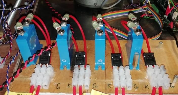
2

   Unidirectional DC CB may suffice in many applications and
potential applications are studied in [15]. As an illustration, Fig.
2 shows a 4-terminal (5-node) DC grid which employs 4
unidirectional DC CBs. As an example, DC CB5_3 would be
required to operate only for the shown fault (on cable 53). There
is no benefit in having bidirectional operation, not even for
back-up protection since AC CBs on each radial line act as
back-up protection.

                                                                              Fig. 3. Bidirectional HVDC CB with 2 main valves (topology 1)

                     Fig. 1. Unidirectional HVDC CB

                                                                                      Fig. 4. DC grid with a bidirectional HVDC CB

                                                                          In order to break current in both directions, both the auxiliary
                                                                       and main branch need to have bidirectional blocking capability.
                                                                       Since LCS is typically implemented as a 3x3 matrix of IGBT
                                                                       modules [16] and thus constitutes a very small portion of the
                                                                       total DC CB cost, bidirectional blocking capability of the
           Fig. 2. Radial DC grid with 4 unidirectional HVDC CBs       auxiliary branch is achieved by simply adding another LCS
         Bidirectional DC CB                                           facing the opposite direction. With this arrangement, operating
                                                                       time and control of the auxiliary branch remain unaffected,
    A bidirectional HCB will have two main valves as described
                                                                       however, conduction losses are increased compared to
in [9] and for completeness illustrated in Fig. 3. This topology
                                                                       unidirectional topology.
is very similar to unidirectional topology shown in Fig. 1, the
                                                                          On the other hand, achieving bidirectional blocking
only difference being that both the LCS and main branch are
                                                                       capability of the main branch requires two main valves which
implemented in bidirectional configuration with two valves,
                                                                       leads to higher cost, size and weight compared to unidirectional
doubling the count of semiconductors.
                                                                       solution. The HCB with two main valves as shown in Fig. 3,
    Fig. 4 shows a 4-terminal (6-node) DC grid with a single
                                                                       will be labelled topology 1. Two new topologies will be
bidirectional DC CB. In this case the grid has two protection
                                                                       investigated:
zones (as indicated), and DC CB6_5 would be required to
                                                                          1. Unidirectional main valve with 2 UFDs (topology 2)
operate for a fault on any location in this DC grid.
                                                                          2. Unidirectional main valve with 4 UFDs and 4 LV
    However, in most applications in complex DC grids,
                                                                               switches (topology 3).
assuming fully or partially selective protection, primary
protection function will be achieved with unidirectional DC
                                                                              III. UNIDIRECTIONAL MAIN VALVE WITH 2 UFDS
CBs. The back-up protection and bus-bar protection, if these are
required, will demand bidirectional breaking function of some                  Topology description
installed DC CBs.                                                      Fig. 5 shows bidirectional HCB with a single main valve and 2
    In the open and closed states, system-level performance of         double-throw UFDs. The bidirectional breaking capability is
the unidirectional and bidirectional DC CB types is essentially        achieved using double-throw UFDs S3 and S4 to route the
the same as they block or conduct current in both directions.          current in the positive direction through T2 regardless of the line
Bidirectional current blocking of open HCB is achieved by              current direction. S3 and S4 are controlled simultaneously and
having RCB open. Meanwhile, antiparallel diodes in the LCS             have two positions, 0 and 1. If DC current Idc is positive then
ensure that current can flow in both directions through the            position 1 directs current IT2 in positive direction through T2. If
auxiliary branch when the breaker is closed.                           Idc is negative, then position 0 directs current IT2 in positive
    The main difference between the two topologies is the              direction through T2. The justification for this topology is that
inability of a unidirectional HCB to open under current in both        cost of two UFDs (mechanical devices) is expected to be
directions. As shown in Fig. 1, IGBTs of both LCS and T2 carry         favorable compared to cost of a full main valve T2. The UFDs
the current in only one direction while antiparallel diodes carry
it in the other.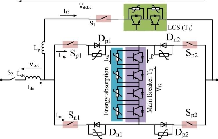
3

S3 and S4 are similar to S1, and are assumed to operate in 2ms
[17], except that double throw contacts are employed.
   A schematic of double-throw UFD is shown in Fig. 6. The
switch topology is similar to a conventional single-throw UFD,
which has Thomson coils (TCs) to move actuator disks in both
directions [17]. Similarly as single throw UFD, the double-
throw UFD has two positions. The difference is only in the
contact assembly, since one of the rods has two sets of contacts
attached to it, also known as throws.
   There have been no reports of double-throw UFDs being
manufactured for HV applications. However, given the
similarities with single-throw UFDs which have been built and
tested at high voltage [8],[11],[17], it is unlikely that any major
obstacles would be encountered in making these devices.

      Fig. 5. Bidirectional HVDC CB with single main valve and 2 UFDs
                                  (topology 2)

                                                                              Fig. 7. Control logic of bidirectional HCB with single T2 and 2 UFDs

                                                                          obtained directly from Idc measurements. The sign of VDCCB is
                                                                        used to determine the closing direction of the breaker and this
                                                                        measurement can be obtained as a difference between cable and
                                                                        DC bus voltage. Once the direction is determined, internal
                                                                        opening (Ko1,Kop,Kon) and closing (Kcp,Kcn) signals are
                                                                        generated. The opening sequence is as follows:
                                                                        1. Kgrid is set to zero which initiates HCB opening.
              Fig. 6. Single pole, double-throw UFD schematic
                                                                        2. Directional logic determines the opening direction. Setting
                                                                            Kop or Kon to 0 initiates opening in the positive or negative
       Control logic                                                        direction respectively.
   Control system for this topology is shown in Fig. 7. The             3. If the sign of Idc corresponds to the sign of VLdc (indicates
control signals for mechanical switches are named S1…S4 while               current differential) and S3 and S4 are aligned in the desired
feedback (status) signals are named S1s…S4s (open - 0, closed -             opening direction, Ko1 is set to 1 which opens T1. This logic
1). Control signals of semiconductor switches, as well as                   ensures that the current will not change direction if
current measurements, are show in Fig. 5.                                   commutated into T2, as well as that S3 and S4 have finished
   The protection relay will normally be sending one signal to              moving.
HCB [14], denoted as Kgrid in Fig. 7. The block “directional            4. If sign of Idc differs from the sign of VLdc, opening of T1 is
logic” uses current, voltage and switch position measurements               delayed, since this indicates that current will change
(switch positions S3s and S4s, line current Idc, inductor voltage           direction. When current crosses zero, the opening process
VLdc and voltage across the whole HCB VDCCB) to determine if                continues normally.
DC CB is oriented in the expected direction of current in either        5. If S3 and S4 are not oriented in the direction of (fault)
opening or closing. This directional HCB logic can be                       current, a command is issued to change the position. The
implemented either in relay or in the HCB itself. Not all                   position change of S3 and S4 takes 2 ms (Tufd).
measurements need to be internal to the breaker. VLdc is only           6. Once the opening criteria for the auxiliary branch are
used to determine the sign of Idc differential which can also be            satisfied, T1 is turned off and current commutates into the
                                                                            main branch. When current through S1 falls below its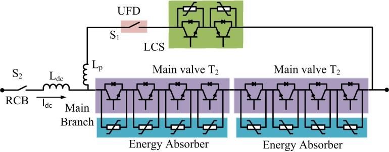
4
chopping capability Iufd (assumed as 1 A [17]) S1 opening of lateral contact overlap, UFD remains a closed circuit for
command is given and it opens in 2 ms. approximately 0.4 ms after the pulse is given, and it starts arcing
T2 turns off as soon as confirmation is received that S1 is 0.4 ms before the final closed state.
open. Current commutates into the energy absorption Current breaking operation of the topology 2 HCB prototype
branch which isolates the fault. is demonstrated in Fig. 11. S3 and S4 are initially oriented in the
7. S2 opens when the residual current falls below the limit Ires opposite direction from the fault to simulate worst-case
(assumed as 10 A). This step takes around 30 ms (Tres). scenario. Because of negative current, T1 conducts for the first
The closing sequence is: 2 ms while S3 and S4 reconfigure positions. After S3 and S4
1. Kgrid is set to 1 which initiates the closing sequence. change position, T1 turns off and current commutates into the
Closing direction is determined from the sign of VDC CB. main branch. It takes additional 2 ms for S1 to open. The total
2. S3 and S4 are directed to the corresponding position by time for voltage to recover is 4 ms, and then it takes additional
setting Kcp or Kcn to 0. 4 ms for current to reduce to zero.
3. Closing command is sent to S2 which closes in 30 ms. The applied DC voltage is 900V, while peak voltage stress on
4. Upon receiving confirmation that S2 is closed, T2 turns on switches is limited to 1500V by the energy absorbers. The
at which point DC CB starts conducting. authors have obtained these encouraging results on low-voltage
5. Closing of main valve initiates 2 ms closing of S1. prototypes only, and further tests at higher voltages and currents
6. Upon receiving confirmation that S1 is closed, T1 turns on would be required as the next development step.
and current commutates into the auxiliary branch.
The total opening time of this topology is either 2 or 4 ms, IV. UNIDIRECTIONAL MAIN VALVE WITH 4 UFDS AND 4 LV
depending on the initial orientation of S3 and S4 with respect to SWITCHES
the fault current direction. Faster opening is achieved if the two
Topology description
are aligned since S3 and S4 do not operate. S3 and S4 do not carry
any current in closed state and can be manipulated. This can be Fig. 12. shows bidirectional HCB topology where main
used to an advantage by maintaining S3 and S4 orientation in the branch consists of a single T2 valve, 4 UFDs and 4 LV (low
direction with higher probability of fault occurrence, such as
towards the cable rather than a DC bus. Nevertheless, Ldc needs
to be dimensioned for the worst-case scenario (4 ms opening)
which implies a twofold increase in installed series inductance
compared to topology 1.
Simulation results
PSCAD Simulation results for a 320 kV, 16 kA HCB with 2
UFDs are shown in Fig. 8. Main breaker parameters are given
in Table II in the appendix. Fault is applied at 0.3 s in the
negative direction (to study worst case) while trip order is given
when line current exceeds 8 kA. S3 and S4 are initially in
position 0 which requires change in orientation and results in 4
ms breaker opening time. The results verify opening sequence
described in section III. A. Fig. 8 (c) shows that load current
Idc0. Voltage spike
appearing across T1 is caused by parasitic inductance Lp as
analyzed in [16] and is limited by the T1 surge arrester. Fig. 8
(e) shows that all three UFDs block the same voltage (voltages
across S3 and S4 are given for the positive throw).
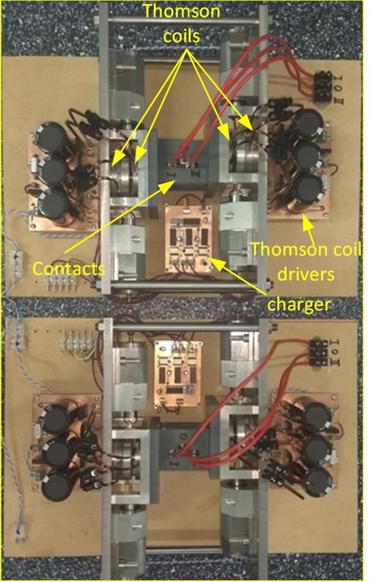
Laboratory hardware demonstration
Experimental verification of topology 2 has been carried out
using 900 V, 500 A DC CB test circuit and HCB prototype,
described in [18]. The main breaker parameters are given in
Table III in the appendix. The low-voltage disconnector S1 is
described in some detail in [19], and two similar double throw
UFDs S3 and S4 are fabricated as shown in Fig. 9.
Fig. 10 shows the component testing results for a single-pole
double-throw UFD. The Thomson coil current shows
approximately 2900A peak, which is required for fast opening.
Both throws are energized with a low voltage of 2 V through 4
Ω resistors giving around 0.5 A in conducting state, which is the
current level that UFD can interrupt. The two signals represent
voltage measured across the resistors on each position of the
UFD. It is seen that total operating time is around 2 ms. Because
Fig. 8. Opening of DC CB topology 2 under negative fault current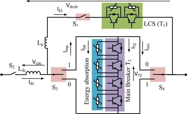
5

                                                                                           Fig. 11. Experimental test response of topology 2.

                 Fig. 9. Two single-pole double throw UFDs.

                                                                                Fig. 12. Bidirectional HVDC CB with a single main valve, 4 UFDs and 4
                                                                                                         LV switches (topology 3).
      Fig. 10. Testing of single-pole double throw UFD. Current: 500A per
                      division. Position I and II: 2V per division.         arrangement will have substantially lower semiconductor count
                                                                            compared with 4 HV-rated diode valves in [12].
   voltage) switches (diodes). LV switches are oriented in pairs               A major advantage of this approach, compared with topology
(Dp1-Dp2 and Dn1-Dn2) and used to route the current through the             2, is that UFDs in the main branch operate simultaneously with
main branch. The arresters across diodes are placed to eliminate            the auxiliary branch UFD S1 so the total opening time remains
voltage spikes at switching, similarly as with LCS, and have no             2ms (same as for topology 1).
energy absorption requirement. If load current is positive,
diodes Dp1 and Dp2 direct current through T2 in the positive                        Control logic
direction. If load current is negative, Dn1 and Dn2                            The control system is shown in Fig. 13. Since all four UFDs
direct current through T2 in the positive direction. Once the               in the main branch are closed in normal (closed) operation,
current direction is established, UFDs of non-conducting LV                 current is redirected using diodes and directional logic is
switches open to provide HV insulation before T2 turns off.                 simpler than with topology 2. The opening sequence is:
Diodes take full current stress (no voltage blocking) while                 1. Kgrid is set to zero which instructs HCBB to open. Opening
UFDs take full voltage stress (no current interruption). This                    direction is determined from the sign of VLdc. Once the sign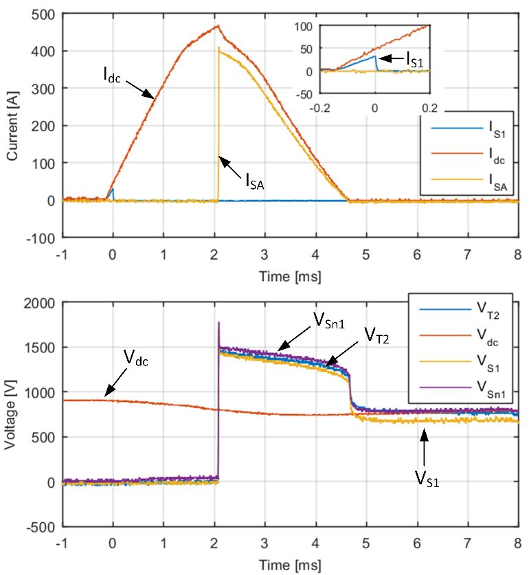
6

          of Idc becomes equal to the sign of VLdc, opening sequence               3.   Upon receiving confirmation that S2 is closed, closing
          is initiated by setting Kop or Kon to 0.                                      signal is sent to either Sp or Sn pair depending on the closing
2.        As T1 turns off, current commutates into the main branch.                     direction.
          When current through UFD falls below their breaking                      4. When either UFD pair closes T2 turns on. HCB starts
          capability Iufd, opening command is given to S1 and 2 of                      conducting at this point.
          UFDs in the main branch. S1 opens simultaneously with Sp                 5. Closing of main valve triggers simultaneous closing of S1
          or Sn pair so the whole process takes only 2 ms.                              and the remaining Sp or Sn pair. This takes 2 ms.
3.        T2 turns off as soon as confirmation is received that S1 and             6. Upon receiving confirmation that S1 is closed, T1 turns on
          Sp or Sn are fully open. Current commutates into the energy                   and current commutates into the auxiliary branch.
          absorption branch which isolates the fault.                                 The total opening time for topology 3 is 2 ms irrespective of
4.        S2 opens when line current falls below the limit Ires.                   fault direction which is a significant improvement compared to
5.        The remaining main branch UFDs open when their current                   topology 2. Since opening time does not differ from topology
          falls below Iufd.                                                        1, Ldc size remains the same. As visible from Fig. 12, the energy
             The closing sequence of topology 3 is:                                absorption branch can be fully isolated using four main branch
1.        Kgrid is set to 1. Depending on the sign of VDC CB, current              UFDs. Depending on the V-I characteristic of the main surge
          direction is determined and corresponding signals Kcp or                 arrester, S2 could be omitted from this topology if arrester
          Kcn are set to 0.                                                        leakage current is below UFD chopping current Iufd.
2.        Closing command is sent to S2 which closes in 30 ms.                        On the downside, this topology requires 5 UFDs, and each of
                                                                                   the 4 additional UFDs will have 2 bushings which increases
                                                                                   space requirement. However, size and weight have not been
                                                                                   analyzed in any depth in this article.
                                                                                           Stresses on diodes
                                                                                      Diodes are crucial new components in this topology, and
                                                                                   their stresses will determine cost-effectiveness of this topology.
                                                                                   The diodes conduct while T2 conducts but also while energy
                                                                                   absorber conducts. The peak current stress is same as for T2, i.e.
                                                                                   peak interrupting current (16kA for the test system). They do
                                                                                   not take load current. The diodes therefore conduct for 10ms-
                                                                                   20ms at most and their thermal stress is larger than on T2. The
                                                                                   simplest thermal management would be to install multiple
                                                                                   parallel diodes to avoid forced cooling.
                                                                                      The peak voltage stress happens at the instant when current
                                                                                   is commutated from the auxiliary branch to the main branch.
                                                                                   The two diodes that do not conduct will experience reverse
                                                                                   voltage equal to the voltage drop across T2 at the commutation.
                                                                                   The calculation of voltage stress on LCS is presented in detail
                                                                                   in [16], and a similar procedure can be used. However, parasitic
                                                                                   inductances Lp and others have no impact since diodes do not
                                                                                   have fast turn off, and the expected peak voltage stress for
                                                                                   320kV HCB is 2-3kV.
                                                                                      The operating instant when T2 turns off should be carefully
                                                                                   analyzed since the peak current is commutated from T2 to the
                                                                                   energy absorber (with substantially higher voltage), while
                                                                                   diodes should continue to conduct. This is very unusual
                                                                                   operating condition for diodes, and the diode current should
                                                                                   remain higher than the holding current (in tens of Ampere). In
                                                                                   case when HCB is interrupting very low current, diode current
                                                                                   may drop below holding current and diodes may turn off before
                                                                                   UFD opens. The arresters across diodes ensures that in such
                                                                                   case any voltage spike will not destroy diodes.
                                                                                          Simulation results
                                                                                      The opening process of a 320 kV, 16 kA topology 3 HCB is
                                                                                   shown in Fig. 14, using identical test as for topology 2.
                                                                                      Main breaker parameters are given in Table II in the
                                                                                   appendix. Simulation results show that DC CB opens in 2 ms
                                                                                   irrespective of fault current direction. It is seen that the voltage
                                                                                   across diodes remains low.
         Fig. 13. Control logic for bidirectional HVDC CB with single T2, 4 UFDs
                                         and 4 LV switches.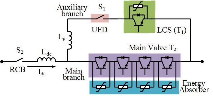
7

  Closing process in the positive direction is shown in Fig. 15.        bidirectional HCB with two main valves. Voltage
Control signals are not shown since the closing command                 measurements across UFDs confirm they are fully open when
(Kgrid=1) is given at 0.4 s (outside of the time range). Line           the main valve turns off.
current commutation into and from the main branch is smooth
and no overvoltages appear across LV switches.

                                                                                  Fig. 15. Simulation of closing sequence of topology 3

          Fig. 14. Opening of topology 3 under negative fault current

        Laboratory demonstration
   A photograph of 4 diodes (ON Semi RURG8060, 600V, 80A)
with their arresters is shown in Fig. 16. Low voltage (130V,
EPCOS B72240B0750K001) arresters are used to confirm that
                                                                                 Fig. 16. 4 ON Semi diodes and arresters in topology 3
proposed DC CB operates well with low diode voltage stress.
   The test response of hardware HCB topology 3 is shown in
Fig. 17. All parameters are given in Table III in the appendix.
   Since current measurements are performed using a
combination of AC and DC probes, the curves do not perfectly
overlap. The additional diode resistance also causes some
difference compared with the other topologies. Nevertheless,
test results demonstrate that the opening time is identical to the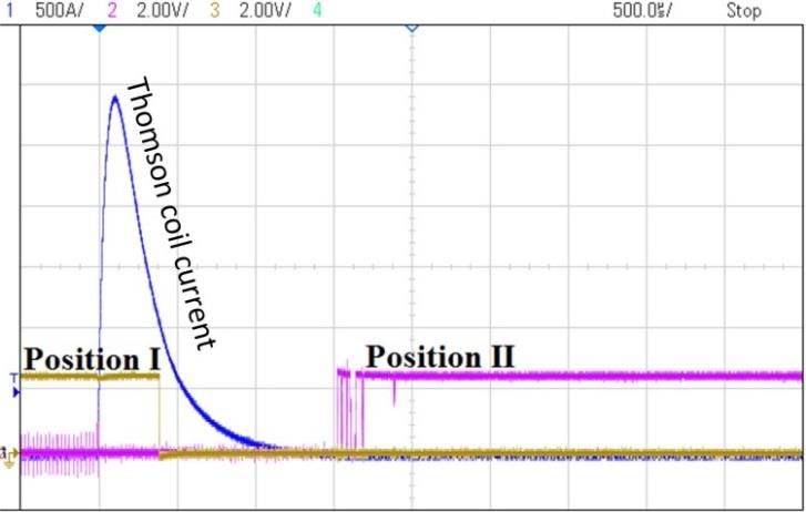
8

                                                                                     Table I Comparison of bidirectional HVDC CB.
                                                                                             Two T2 valves       2 UFDs     4 UFDs, 2 thyristors
                                                                          Operating time          2 ms           2-4 ms            2 ms
                                                                            HV valve                2               1                1
                                                                              LCS             Bidirectional   Bidirectional    Bidirectional
                                                                             UFDs                   1               3                5
                                                                             Diodes                 0               0                4
                                                                            Inductor            100 mH          200 mH            100 mH

                                                                                                 VI. CONCLUSION
                                                                       Three bidirectional HCB topologies are analyzed in this
                                                                    paper. Topology 1 uses two HV valves which substantially
                                                                    increases semiconductor count, size and weight compared to a
                                                                    unidirectional HCB. The newly proposed bidirectional
                                                                    topology 2 uses only a single HV valve with two double-throw
                                                                    UFDs. However, it is concluded that the opening time in the
                                                                    worst-case scenario is doubled. The proposed topology 3 uses a
                                                                    unidirectional IGBT valve with additionally 4 UFDs and 4
                                                                    diodes. This topology offers the same system-level
                                                                    performance as topology 1 but with half the number of
                                                                    semiconductors. On the other hand, increased number of
                                                                    mechanical components makes topologies 2 and 3 less reliable
                                                                    than topology 1. The experimental results on 900V 500A DC
                                                                    CBs have confirmed theoretical findings.

              Fig. 17. Experimental test response of topology 3               VII. APPENDIX. 320KV, AND 900V TEST SYSTEMS
                                                                                      Table II Parameters of the 320kV, 16kA HCB.
               V. COMPARISON OF TOPOLOGIES                                   SL.NO.                    PARAMETER                    VALUE
                                                                                1                      Voltage rating               320 kV
   Comparison between the three bidirectional HCB topologies
                                                                                2                      Current rating                 2 kA
is given in Table I. Topology 2 is the most cost-effective with                 3               Maximum Breaking current             16 kA
the lowest number of components (electrical and mechanical).                    4                   UFD operation time                2 ms
However, since opening time may be twice as long compared                       5            Limiting inductor Ldc (topology 2)     200 mH
to the other two topologies (depending on current direction), it                6            Limiting inductor Ldc (topology 3)     100 mH
requires double the series inductance (to ensure adequate peak                  7                  Parasitic inductance Lp          0.2 mH
current) which also implies double the energy rating of energy                        Table III Parameters of the 900V, 500A HCB.
absorbers. Also, this topology demands development of new                    SL.NO.                   PARAMETER                     VALUE
device, double-throw UFD. This topology is nevertheless                         1                      Voltage rating                900 V
                                                                                2                      Current rating                 30 A
substantially more cost-efficient than topology 1 because of the
                                                                                3               Maximum Breaking current             500 A
lower number of semiconductors.                                                 4                   UFD operation time                2 ms
   Topology 3 is the most attractive topology, offering identical               5            Limiting inductor Ldc (topology 2)      7 mH
system-level performance as topology 1 at half the number of                    6            Limiting inductor Ldc (topology 3)     3.5 mH
semiconductors. Since topology 2 requires over-dimensioning
of DC inductor and surge arresters, topology 3 would likely                                 VIII. ACKNOWLEDGMENT
have the lowest overall cost.                                       The authors are thankful to Mr R. Osborne for help with the
   Considering of immaturity of HCB technology, it is               experimental studies.
reasonable to expect higher UFD failure rate compared to
electronic switches. Moreover, modular design of the HV valve                                    IX. REFERENCES
and LCS makes them tolerant to single component failure
                                                                    [1]    D Jovcic and K Ahmed "High Voltage Direct Current Transmission:
whereas the same does not apply for UFDs. Topology 1 can                   Converters Systems and DC Grids", Wiley, 2015.
therefore be considered the most reliable since it contains the     [2]    CIGRE joined WG A3 and B4.34 “Technical Requirements and
least amount of critical components (only a single UFD).                   Specifications of State of the art HVDC Switching Equipment” CIGRE
   With topologies 2 and 3, HCB might still operate if one (or             brochure 683, April 2017.
in some cases even two) main branch UFDs malfunction,               [3]    K. Tahata, S. Oukaili, K. Kamei, et al., “HVDC circuit breakers for
however, it can do so in only one direction.                               HVDC grid applications,” Proc. IET ACDC 2015 conference,
                                                                           Birmingham, UK, pp. 1-9, Feb 2015.
                                                                    [4]    T. Eriksson, M. Backman, S. Halen, A low loss mechanical HVDC
                                                                           breaker for HVDC grid applications, B4-303, CIGRE 2014, Paris.
                                                                    [5]    L Ängquist at all, “Design and test of VSC assisted resonant current
                                                                           (VARC) DC circuit breaker” 15th IET International Conference on AC
                                                                           and DC Power Transmission (ACDC 2019), Coventry, UK, Feb. 2019.
9

[6]       W. Grieshaber, J. Dupraz, D. Penache, et al., “Development and Test of a           Mohammadhassan Hedayati (S'14-M'16) He
          120kV direct current circuit breaker,” Proc. CIGRÉ Session, Paris,             received his B.Tech. degree in electrical engineering
          France, pp. 1-11, Aug 2014.                                                    from the Islamic Azad University, Kazeroon, Iran, in
[7]       A. Shukla and G. Demetriades, “A survey on hybrid circuit-breaker              2006. He received his ME and PhD. degrees from
          topologies,” IEEE Trans. Power Del., 30, (2), pp. 627-641, 2015.               Indian Institute of Science (IISc) Bangalore, India in
[8]       R.Derakhshanfar et al, “Hybrid HVDC breaker – A solution for future            2010 and 2015 respectively. He is currently a research
          HVDC system” CIGRE paris 2014, B4-304.                                         fellow at University of Aberdeen, Aberdeen, UK. His
                                                                                         primary areas of interests are in Hybrid DC CB, power
[9]       Häfner, J., Jacobson, B.: ‘Proactive Hybrid HVDC Breakers - A key              electronics, motor drives, active damping, common
          innovation for reliable HVDC grids’. Proc. CIGRE 2011 Bologna Symp.,           mode and EMI filters and high-power converters.
          Bologna, Italy, Sep 2012, pp. 1-7
[10]      CIGRE WG B4.52 “Feasibility of HVDC grids” CIGRE technical
          brochure 533, Paris, April 2013
[11]      G.F. Tang, X. G. Wei, W.D. Zhou, S. Zhang, C. Gao, Z.Y. He, J. C. Zheng
          “Research and Development of a Full-bridge Cascaded Hybrid HVDC
          Breaker for VSC-HVDC Applications”, A3-117, CIGRE Paris 2016
[12]      B. Yang, D. Cao, W. Shi, W. Lv, W. Wang, B. Liu, “A novel
          commutation-based hybrid HVDC circuit breaker”, CIGRE B4
          colloquium, Winnipeg, October 2017.
[13]      Chuanyue Li, Jun Liang, and Sheng Wang, “Interlink Hybrid DC Circuit
          Breaker”, IEEE Transactions on industrial electronics, vol. 65, no. 11,
          November 2018.
[14]      W. Lin, D. Jovcic, S. Nguefeu and H. Saad, “Modelling of High Power
          Hybrid DC Circuit Breaker for Grid Level Studies,” IET Power
          Electronics, Vol. 9, issue 2, February 2016, pp 237-246
[15]      A. Jehle, D. Peftitsis, and J. Biela, “Unidirectional hybrid circuit breaker
          topologies for multi-line nodes in HVDC grids,” in Proc. 18th Eur. Conf.
          Power Electron. Appl., Karlsruhe, Germany, 2016,pp. 1–10
[16]      Hassanpoor, A., Häfner, J., Jacobson, B.: ‘Technical assessment of load
          commutation switch in hybrid HVDC breaker’, IEEE Transactions on
          Power Electronics, 2015, 30, (1), pp. 5393-5400
[17]      P. Skarby and U. Steiger, “An Ultra-fast Disconnecting Switch for a
          Hybrid HVDC Breaker– a technical breakthrough”, Proc. CIGRÉ
          Session, Alberta, Canada, pp. 1-9, Sep 2013
[18]      M Hedayati and D. Jovcic “Reducing peak current and energy dissipation
          in hybrid HVDC CBs using Disconnector voltage control” IEEE
          Transactions on Power Delivery, Vol 33, isue 4, pp 2030-2038.
[19]      M. Hedayati, D. Jovcic “Low Voltage Prototype Design, Fabrication and
          Testing of Ultra-Fast Disconnector (UFD) for Hybrid DC CB” CIGRE B4
          colloquium, Winnipeg October 2017

                                 X. BIOGRAPHIES

                             Dragan Jovcic (S'97-M'00-SM'06) obtained a
                          Diploma Engineer degree in Control Engineering
                          from the University of Belgrade, Serbia in 1993 and
                          a Ph.D. degree in Electrical Engineering from the
                          University of Auckland, New Zealand in 1999. He is
                          currently a professor with the University of
                          Aberdeen, Scotland where he has been since 2004. In
                          2008 he held visiting professor post at McGill
                          University, Montreal, Canada. He also worked as a
                          lecturer with University of Ulster, in the period 2000-
2004 and as a design Engineer in the New Zealand power industry, Wellington,
in the period 1999-2000. His research interests lie in the HVDC, FACTS, dc
grids and control systems.

                             Mario Zaja (S’16) obtained Bachelor’s degree in
                         Electrical Power Engineering from University of
                         Zagreb, Croatia in 2013 and Master’s degree in Power
                         Electronics and Drives from Aalborg University,
                         Denmark in 2015. He is currently pursuing a PhD
                         degree at the University of Aberdeen, Scotland on the
                         topic of dc grid protection. He also worked at the
                         Converter Control department of Vestas Wind Systems
alongside his studies in the period 2014-2015. His research interests include dc
grids, renewable energy sources and electric vehicles.
You can also read


