HYBRID ENERGY TRANSFER LINE WITH LIQUID HYDROGEN AND SUPERCONDUCTING MGB 2 CABLE FIRST EXPERIMENTAL PROOF OF CONCEPT
←
→
Page content transcription
If your browser does not render page correctly, please read the page content below
untitled - ,DanaInfo=ieeexplore.ieee.org+06407832.pdf                                          https://browser-ras.jpl.nasa.gov/ielx5/77/6366257/,DanaInfo=ieeexplore....

         IEEE TRANSACTIONS ON APPLIED SUPERCONDUCTIVITY, VOL. 23, NO. 3, JUNE 2013                                                                       5400906

          Hybrid Energy Transfer Line With Liquid Hydrogen
               and Superconducting MgB2 Cable First
                    Experimental Proof of Concept
                        V. S. Vysotsky, Senior Member, IEEE, A. A. Nosov, S. S. Fetisov, G. G. Svalov, V. V. Kostyuk,
                               E. V. Blagov, I. V. Antyukhov, V. P. Firsov, B. I. Katorgin, and A. L. Rakhmanov

                                                                                 (Invited Paper)

            Abstract The tr ansfer of massive amounts of both electr ical                   production. It may be applied to hydropower stations as well.
         and chemical power over long distances will present a major                        Speaking on green energy, the world-wide deployment of new
         challenge for the global ener gy enter pr ise in the future. Attr action           forms of the electricity generation such as wind, geothermal or
         of hydrogen is apparent as a chemical ener gy agent, possessing
         among the highest ener gy density content of var ious common fuels,                solar cannot occur without a renewed investment in the energy
         whose combustive waste is simply water. It could be tr ansfer red                  transmission infrastructures. New connections should be built
         via cr yogenic tubes being liquid at temper atures 18 26 K. The                    to link areas with vast potential to deliver the energy to the areas
         usage of gr atis cold to cool a superconducting cable made of a                    that have demands for power. Different energy carriers could be
         proper superconductor per mits to deliver extr a electr ical power                 used: oil, gas, and certainly electricity.
         with the same line. In this paper, we descr ibe the exper imental
         modeling of this concept via a combined MgB2 -cr yogenic dc super-                    The problem of the power transfer in the amounts of few
         conducting cable refr iger ated by singlet phase liquid hydrogen.                  GWs and more is discussing for many years. One of the
         We present the design, constr uction details, and test results of a                initial discussions returns us back far to 1967 and consider
         10-m prototype, focusing on choice of MgB2 cable and cr yostat                     low-Tc superconductors (LTS) [1]. A few LTS high power
         technologies. We also discuss the oppor tunities and possibilities                 superconducting cables based on Nb3Sn has been developed
         for future pr actical deployment of such hybr id ener gy deliver y
         systems.                                                                           [2] [4] and tested in the end of 70-ties early 80-ties. Anyway
                                                                                            the AC cables put into effect a delivery only for distance up to
           Index Terms Ener gy tr ansmission, liquid hydrogen, MgB2 ,                       35 40 km from over rising of the reactive power.
         superconducting cables.
                                                                                               Superconductivity is the choice for the electricity transmis-
                                                                                            sion by DC cables. Absence of any losses except for cooling
                                    I. I NTRODUCTION
                                                                                            makes DC superconductivity very effective. It was also dis-

         T     HE ENERGY transmission from a production site to the
               place of its consuming is as much important task as
         just energy production itself. Very often the energy production
                                                                                            cussed for a long time starting from [1] and later, for example in
                                                                                            [5]. One of the most extensive reviews of the previous projects
                                                                                            of the AC and DC cable may be found in [6].
         facilities are located faraway from densely populated areas.                          The discovery of high temperature superconducting (HTS)
         It can apply to both nuclear and future thermonuclear energy                       materials has inspired new developments for energy trans-
                                                                                            mission by means of superconducting cables. It is generally
            Manuscript received October 5, 2012; accepted January 3, 2013. Date of          acknowledged that superconducting power cables are the most
         publication January 9, 2013; date of current version January 30, 2013. This        advanced HTS applications and they are practically near the
         study was performed in the framework of the program Basic Principles of            commercialization. Up to now the biggest HTS AC power cable
         Development of Power Systems and Technologies, Including High Temperature
         Superconductors supported by the Presidium of the Russian Academy of               is 600 m in length and has rated power about 570 MWA [7].
         Sciences.                                                                             Nevertheless, in the future power transmission demands
            V. S. Vysotsky, A. A. Nosov, S. S. Fetisov, and G. G. Svalov are with
         Russian Scienti c R&D Cable Institute, 111024 Moscow, Russia (e-mail:
                                                                                            could be more than tenths of GW. The discussions about such
         vysotsky@ieee.org).                                                                power grids renewed again with HTS discovery, see for exam-
            V. V. Kostyuk is with Russian Academy of Science, 119991 Moscow, Russia.        ple [6]. The similar issues were discussed during symposium
            E. V. Blagov is with the Institute of Nanotechnology for Microelec-
         tronics, Russian Academy of Sciences, 119991 Moscow, Russia (e-mail:
                                                                                            [8]. One of ideas that were in the wind for a long time is to
         blagovev@mail.ru).                                                                 use the liquid hydrogen both as a cryogen and as an extra fuel
            I. V. Antyukhov, V. P. Firsov, and B. I. Katorgin are with Moscow               to provide a very high ow of the energy. This led to the idea
         Aviation Institute-Technical University, 125993 Moscow, Russia (e-mail:
           rsovval@mail.ru).                                                                of a super-grid [9] that is more attractive as the necessity to
            A. L. Rakhamnov is with Institute of Theoretical and Applied Electrodynam-      use of hydrogen in the power energetics and for other purposes
         ics of RAS, 125412 Moscow, Russia (e-mail: alrakhmanov@mail.ru).                   becomes a rather popular point of view.
            Color versions of one or more of the gures in this paper are available online
         at http://ieeexplore.ieee.org.                                                        We have to acknowledge that the concept of the dual delivery
            Digital Object Identi er 10.1109/TASC.2013.2238574                              of chemical and electrical power employing just MgB2 wire

                                                                          1051-8223/$31.00    2013 IEEE

1 of 6                                                                                                                                                     3/29/2014 1:34 PM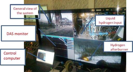
untitled - ,DanaInfo=ieeexplore.ieee.org+06407832.pdf                           https://browser-ras.jpl.nasa.gov/ielx5/77/6366257/,DanaInfo=ieeexplore....

          5400906                                                     IEEE TRANSACTIONS ON APPLIED SUPERCONDUCTIVITY, VOL. 23, NO. 3, JUNE 2013

                                                                          TABLE I
                                                      P ROPERTIES OF M OST C OMMON S UPERCONDUCTORS

          cooled by liquid hydrogen through a single cable corridor was               insert a cable inside a cryogenic line and connect to
            rst mentioned by P.M. Grant as early as 2001 2002 [10], [11],             cryogenic system and electric grid;
          very shortly after MgB2 has been discovered in January 2001.                deliver it to a test facility equipped with a liquid hydrogen
          This concept has been termed as hydricity after hydrogen +                  supply;
          electricity . Later in a lot of papers, both popular and peer-              make tests.
          reviewed, the problems of the hybrid energy delivery were               Here we are presenting the detailed data on the supercon-
          discussed using a hydricity concept [12] [19].                       ducting wire and cable which were used, and the test results of
             Combusting hydrogen as a fuel would be the optimal choice.        the prototype of a hybrid energy transfer line. The details of the
          It has highest fuel ef ciency among others 120 MJ/kg. It             cryogenic system were presented earlier in [24]; the earliest test
          could be transferred in a liquid state through a long cryogenic      results presented in [25].
          transferring line to place of consuming. We have to note that
          liquid hydrogen is the best cryogen having the cooling capacity
                                                                                             II. C HOICE OF S UPERCONDUCTOR
          446 kJ/kg against 20.3 kJ/kg for LHe and 199 kJ/kg for LN2 .
          Thus, the idea to place into a transfer line with liquid hydrogen       The most common superconductors that are used in applica-
          a superconducting cable to transmit the electricity in parallel is   tions and are available at the market are listed in the Table I.
          quite natural. Besides references mentioned, this idea has been      The liquid hydrogen has temperature 20 K at atmospheric
          discussed in [20] [22] as well.                                      pressure. Thus it is out of the question to use common LTS
             The question is what kind of superconductor should be used        superconductors. The choice should be done between supercon-
          for the cable in a hydrogen energy transfer line. It was shown       ductors that can work at LH2 . They are either HTS or MgB2 .
          that an optimal choice could be recently discovered MgB2 with        HTS of both generations (1G and 2G) are freely available at the
          a critical temperature of 39 K [20].                                 market. But considering the price (see the Table I) and the good
             To conclude, there are a lot of theoretical and simulation        superconducting properties including the high stability at 20 K
          works discussing possible hybrid energy transfer lines using         [26], the MgB2 is the preferable choice for a system with liquid
          liquid hydrogen both as a fuel and cryogen, and a supercon-          hydrogen.
          ducting power cable to deliver extra electrical energy [8] [23].        Only two companies are selling MgB2 wires right now:
          Nevertheless no any experimental works have been performed           Hyper Tech Research Inc. in Columbus, Ohio, USA [27] and
          so far to proof this concept. In our work we took the challenge to   Columbus Superconductor (CS) SpA in Genoa, Italy [28].
          perform the experimental study of hybrid energy transmission.           The rst company offers MgB2 wires that should be heat
             The major goals of our work were:                                 treated after the making a device. Assuredly they are good
                    To learn how to work with LH2 ;                            for any winding and magnets, but de nitely are not suitable
                    To get the rst experimental data about hybrid energy       for the long cables. It is dif cult to imagine heat treatment of
                    transport systems with LH2 and superconductivity.          long cable with 100 200 m length that could be bending and
                                                                               unbending after heat treatment. On the other hand, the CS offers
            To succeed in these goals we had to:                               long length wires that can be used without heat treatment. The
                    choose the proper superconductor: that is surely MgB2 ;    shape of the wires is varying from round and quadratic wires to
                    check characteristics of MgB2, its manufacturability and   different at tapes [28].
                    how to work with it;                                          Recently we developed the technology for HTS power cables
                    design and make a superconducting cable with it;           made of at HTS tapes [29]. That is why for this project we
                    develop and manufacture a liquid hydrogen cryogenic        also decided to use at tape to employ the same cabling and
                    line;                                                      insulation technology as for HTS power cables.

2 of 6                                                                                                                                      3/29/2014 1:34 PM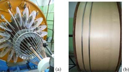
untitled - ,DanaInfo=ieeexplore.ieee.org+06407832.pdf                                      https://browser-ras.jpl.nasa.gov/ielx5/77/6366257/,DanaInfo=ieeexplore....

         VYSOTSKY et al.: HYBRID ENERGY TRANSFER LINE W/ LIQUID HYDROGEN AND SUPERCONDUCTING MgB2 CABLE                                                       5400906

         Fig. 1. Dependence of critical current on magnetic eld at different tempera-
         tures for the at MgB2 wire used in our experiment [28]. Cross-section of the
         wire is shown.

            The selected tape and its critical current dependence on eld
         and temperature obtained from [28] are shown in Fig. 1. The
                                                                                        Fig. 2. MgB2 cable design: (a) sketch of cross-section with sizes shown;
         cross section of the wire is: 3.64 mm 0.65 mm; MgB2 cross                      (b) 3D view of cable; (c) cross-section of a cable; and (d) photo of the cable
         section 12% of total area; cross section of copper 15% of                      model.
         total area. The minimum diameter of bending with no degrada-
         tion of critical current speci ed by CS is 110 mm.
            As there were no speci c data about critical currents at
           20 K in self eld for the wire selected we used some extrapo-
         lation of data from CS shown in Fig. 1, that returned expected I c
         (20 K) 520 540 A. This value was used for the preliminary
         design of the cable. Later we performed measuring of I c(T )
         for this wire and found that there is some scattering of I c along
         wires and evaluated the in uence of scattering on the current of
         a cable [29]. Anyway the preliminary estimation returned fair
         result for the cable current evaluation.
                                                                                        Fig. 3. Cable production illustrations: (a) pay off wires from a cabling
                                                                                        machine and (b) cable on a take up drum.
                      III. C ABLE D ESIGN AND P RODUCTION
                                                                                        ness of 1 mm allowed the cable to operate in principle at
            The design of a prototype of a superconducting MgB2 cable                   voltages more than 20 kV. In Fig. 2 are shown: the sketch of
         consists of three elements: a former, current carrying layers                  cross section of the cable with all sizes (Fig. 2(a)), 3D view
         and insulation (Fig. 2(a)). The former is a central element that               of the cable (Fig. 2(b)); cross-section (Fig. 2(c)) and photo of
         performed the supporting function. It consists of:                             the MgB2 cable model (Fig. 2(d)). The cable had a length about
                the main supporting stainless steel spiral that formed a                10 m. At one end both current layers were connected by
                  12 mm diameter internal channel for the ow of liquid                  jumpers to provide the returning current. Thus, the total length
                hydrogen;                                                               of the current carrying element considering the two layers
                twisted winding of copper wires with a total cross section              assembly was 20 m. We expected that the critical current of
                suf cient to ensure reliable protection of the supercon-                the cable could be 2.5 3 kA at temperature 20 K.
                ducting current carrying layer in case of short circuit                    The cable has been manufactured with the standard cabling
                fault;                                                                  equipment in JSC VNIIKP and with the technology devel-
                copper tapes winding providing a smooth outer surface                   oped for HTS power cable production [29]. Some illustrations
                of the former for assembling the superconducting MgB2                   from the cable manufacturing process are shown in Fig. 3.
                tapes which are the main current carrying layer.                           After production the cable has been delivered to the Moscow
            The superconducting current carrying path consists of two                   Aviation Institute to be installed into a cryostat.
         serially connected layers; each of them consists of ve MgB2
         tapes helically wound on the former. The number of tapes has
                                                                                                  IV. H YBRID E NERGY T RANSMISSION L INE
         been selected to ensure the maximum current not more than
         3 kA inasmuch as DC power supplies limited us by this current.                   The Hybrid Energy Transmission Line (HETL) has been
            The insulation consists of 20 layers of a polyimide (Kapton)                described in details in [24], [25]. It consists of a long hydrogen
         tape with the thickness of 50 m. The total insulation thick-                   cryostat with 12 m length, a system for liquid hydrogen

3 of 6                                                                                                                                                          3/29/2014 1:34 PM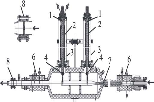
untitled - ,DanaInfo=ieeexplore.ieee.org+06407832.pdf                                             https://browser-ras.jpl.nasa.gov/ielx5/77/6366257/,DanaInfo=ieeexplore....

          5400906                                                                    IEEE TRANSACTIONS ON APPLIED SUPERCONDUCTIVITY, VOL. 23, NO. 3, JUNE 2013

          Fig. 4. Sketch of the HETL experimental test facility: (1) former; (2) current carrying superconductors; (3) outer tube of cryostat; (4) current leads; (5) inner
          tube of the cryostat; (6) polyimide insulation; (7) layered super-insulation; (8) current jumpers; (9) liquid hydrogen storage tank; (10) lling, pressure busting and
          drainage systems; (11) level meter and temperature sensors; (12) liquid hydrogen 12 m transfer line; (13) bayonet connectors ? = 32 mm; (14) drainage 4 m
            exible line ? = 32 mm; (15) jet nozzle ? = 4 mm; (16) drainage exible line ? = 32 mm; L               12 m, is the total length of the cryostat with current leads, the
          length of the cable is 10 m.

          Fig. 5. Current leads for the superconducting cable of the HETL: (1) current
          pathway; (2) insulating polyimide tube with outer bandages; (3) load bear-
          ing support; (4) connectors to join cable; (5) getter; (6) measuring probes;
          (7) connections of exible copper bunches and superconductors; (8) mount-
          ing part.                                                                             Fig. 6. General view of the HETL installed at the test facility: (1) current
                                                                                                leads; (2) cryostat; (3) inlet part; and (4) mounting frame.
          supplying and an experiment control unit to control parameters
          of pressure, ow and temperature.                                                              polyimide insulating tubes with an outer banding and
             The cryostat for the liquid hydrogen transfer at 20 30 K                                   welded edges made from stainless steel anges (2);
          simultaneously ensures cryostating of the MgB2 cable for the                                  a load bearing support to provide the rigidity of the
          transfer of the electricity and the ow of LH2 as a fuel.                                      insulating tube (3);
             The cryostat (Fig. 4) consist of an outer shell (3) with                                   connectors of current pathways (4) with exible copper
          diameter D 4 = 80 mm, a vacuum thermal insulation (7) and                                     bunches and superconductors (7);
          an inner cryostat shell (5) with diameter D 3 = 40 mm. There                                  joints to the cable from power supplies.
          were 6 sections of the cryostat to provide the safe work in case                         At the inlet and outlet of the HETL two sets of measuring
          of vacuum loss in one of sections.                                                    probes have been installed to measure pressure and temperature
             The current leads (terminations) are shown in Fig. 5. The                          of the liquid hydrogen ow.
          current lead consists of:                                                                The HETL was mounted on the rigid frame with 10.2 m
                    a vessel formed by inner and outer shells with diameters                    length and 0.8 m width. The cantilevers of the frame provided
                    270 mm and 370 mm correspondingly;                                          vertical stability of current leads that have 1.26 m height. The
                     exible copper current pathways with 600 mm2 cross-                         total height of the HETL was 2.48 m. General view of the HETL
                    section (1);                                                                installed at the test facility is shown in Fig. 6.

4 of 6                                                                                                                                                                     3/29/2014 1:34 PM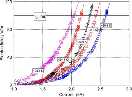
untitled - ,DanaInfo=ieeexplore.ieee.org+06407832.pdf https://browser-ras.jpl.nasa.gov/ielx5/77/6366257/,DanaInfo=ieeexplore....
VYSOTSKY et al.: HYBRID ENERGY TRANSFER LINE W/ LIQUID HYDROGEN AND SUPERCONDUCTING MgB2 CABLE 5400906
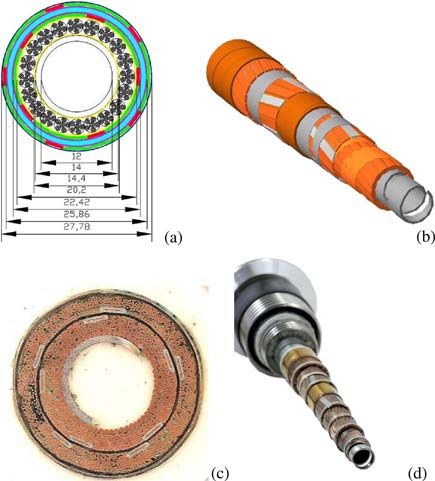
Fig. 7. General view of the control monitor during tests.
V. T EST R ESULTS
Fig. 8. Typical V I characteristics of MgB2 cable at different temperatures.
The experiments with the prototype of the hybrid power
transmission line with forced ow of liquid hydrogen were
carried out in November 2011. They were performed at the
special facility intended for testing oxygen-hydrogen liquid
propellant rocket engines with liquid hydrogen production plant
of the KB Khimavtomatika (Voronezh City). The detailed
results of the cryogenic tests are presented in [24].
The total cooling time was 380 s. To cool the system
2.3 kg of LH2 was used. The evaluated heat losses were below
10 2 W/m, the current lead losses at 2600 A were 300 W.
The variations of temperature during measurements were from
20 K to 26 K, pressure was from 0.12 MPa to 0.5 MPa.
For electrical measurements the three parallel power supplies
Agilent 6680 A were used. Current has been measured by
a standard 7500 A 75 mV shunt. The output signal from
the shunt and voltages from the voltage taps of the cable Fig. 9. Measured dependence of critical current on temperature of MgB2
were measured by a multichannel digital analyzing oscilloscope cable.
Yokogawa DL 850. The operation of current sources and os-
cilloscope was remotely controlled via special communication In Fig. 9 is shown the sum of currents of ve wires from
lines. extrapolation to zero eld data in Fig. 1. The evaluation of
The current carrying characteristics of the MgB2 cable were critical current by averaging its non-uniformity along a wire
recorded at the liquid hydrogen temperatures within 20 26 K, from [30] for ve wires is presented also. One can see the good
with the pressure (as mentioned above) in the interval from 0.12 coincidence of all data that con rm good state of the cable after
to 0.5 MPa, and the mass ow rates in the range from 18 g/s to the industrial manufacturing process.
250 g/s. The pressure drop at 250 g/s did not exceed 28 kPa. The
variation of a temperature along a cable was from 0.2 to 0.8 K
VI. D ISCUSSION AND F UTURE P LANS
depending on the hydrogen ow rate. The conditions of cooling
mean that the liquid phase of subcooled LH2 under pressure With LH2 ow 250 g/s achieved in our cryostat, the energy
was without bubbles. The view of the main control monitor transfer line would deliver 31 MW of chemical power. Su-
during experiments is shown in Fig. 7. perconducting cable at 2.5 kA and 20 kV prospective voltages
The critical current I c(T ) at a given temperature T was would be able to deliver extra 50 MW, so 80 MW in total with
de ned as the current for which the electric eld between only 5 MgB2 tapes.
the voltage taps amounted to 1 V/cm. The temperature, the As it is seen in Fig. 2 it is easy to add at least ten tapes more to
pressure, and the ow rate of liquid hydrogen in the line were our current carrying layers that will increase the transport cur-
monitored simultaneously with the measurement of voltage on rent threefold and corresponding electrical power to 150 MW
the internal and external current layers of the cable. and the total power to 180 MW. The cross section of our
Fig. 8 shows typical experimental plots of voltagesV on energy line is about 50 cm2 only. Therefore the prototype of
the current carrying layers against current I (voltage-current the tested hybrid energy transfer line has potential to deliver a
characteristic). The measurements of critical current were per- power more than 100 150 MW with power ow density more
formed at low voltages up to 3 V. The values of critical than p 3 106 W/cm2 .
currents determined from these plots amounted to 2640 A at The rst thread of the North Stream (gas pipeline
T = 20:4 K and 2020 A at T = 25:7 K. Fig. 9 shows the cor- from Russia to Europe via Baltic sea) has to deliver 27:5
responding dependence of the critical current on temperature. 109 m3 =year of natural gas. This means 870 m3 =s and
5 of 6 3/29/2014 1:34 PM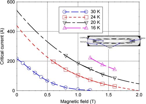
untitled - ,DanaInfo=ieeexplore.ieee.org+06407832.pdf                                       https://browser-ras.jpl.nasa.gov/ielx5/77/6366257/,DanaInfo=ieeexplore....

          5400906                                                               IEEE TRANSACTIONS ON APPLIED SUPERCONDUCTIVITY, VOL. 23, NO. 3, JUNE 2013

          deeming of the fuel ef ciency 40 MJ/m3 [31] this amounts to                            of 50-meter exible superconducting cable, IEEE Trans. Magn., vol. 15,
            3:5 1010 W of power. The typical diameters of gas pipeline                           no. 1, pp. 150 154, Jan. 1979.
                                                                                           [4]   E. B. Forsyth and R. A. Thomas, Performance summary of the
          tubes are 150 cm that means that the cross section is s                                Brookhaven superconducting power transmission system, Cryogenics,
          18 000 cm2 and power density ow p 2 106 W/cm2 . Thus                                   vol. 26, no. 11, pp. 599 614, Nov. 1986.
          our hybrid line being rather modest in size has potential to                     [5]   T. Ishigoka, A feasibility study on a world-wide-scale superconducting
                                                                                                 power transmission system, IEEE Trans. Appl. Supercond., vol. 5, no. 2,
          provide power ow equal to the biggest gas pipelines.                                   pp. 949 952, 1995.
             Acknowledging the result of tests performed the concept of a                  [6]   P. M. Grant, Superconducting lines for the transmission of large amounts
          hybrid energy transmission system with high energy ows, rst                            of electrical power over great distances: Garwin-matisoo revisted forty
                                                                                                 years later, IEEE Trans. Appl. Supercond., vol. 17, no. 2, pp. 1641 1647,
          mentioned in [10], [11] should be considered experimentally                            Jun. 2007.
          proved.                                                                          [7]   J. F. Maguire, F. Schmidt, F. Hamber, and T. E. Welsh, Development
             During our experiments we had no opportunity to perform                             and demonstration of a long length HTS cable to operate in the long
                                                                                                 island power authority transmission grid, IEEE Trans. Appl. Supercond.,
          high voltage tests, so we only estimated the high voltage                              vol. 15, no. 2, pp. 1787 1792, Jun. 2005.
          prospective. Therefore the high voltage test is our rst priority                 [8]   Workshop Program, Transporting Tens of Gigawatts of Green Power
          in the future. Right now we are developing a longer and exible                         to the Market. [Online]. Available: http://www.iass-potsdam.de/sites/
                                                                                                 default/ les/ les/workshop_programme.pdf
          cryogenic line ( 30 m). The cable will be longer also. The test                  [9]   P. M. Grant and S. Eckroad, Functional requirements of a hydrogen-
          plan will include the separate high voltage test and the current                       electric supergrid: Two scenarios supersuburb and supertie, EPRI, Palo
          test with LH2 cooling. Cryostat and new cable should be ready                          Alto, CA, EPRI Rep. 1013204.
                                                                                          [10]   P. M. Grant, Will MgB2 work, The Industrial Physicist, pp. 22 23,
          by the end of this year. The hydrogen test of a new system is                          Oct. Nov. 2001.
          planning for the 2013.                                                          [11]   P. M. Grant, Energy for the City of the future, Ind. Phys., pp. 22 25,
                                                                                                 Feb. Mar. 2002.
                                                                                          [12]   P. M. Grant, Potential electric power applications for magnesium di-
                                                                                                 boride, in Mat. Res. Soc. Symp. Proc., 2002, vol. 689, p. E1.1.
                                    VII. C ONCLUSION                                      [13]   P. M. Grant, Energy for the City of the future, Nucl. Future, vol. 1,
             The rst in the world prototype of hybrid energy transfer line                       pp. 34 37, 2005.
                                                                                          [14]   P. M. Grant, C. Starr, and T. J. Overbye, A power grid for the hydrogen
          consisting of liquid hydrogen cryogenic line and MgB2 based                            economy, Sci. Amer., vol. 295, pp. 76 82, Jul. 2006.
          superconducting cable has been developed and successfully                       [15]   P. M. Grant, The energy SuperGrid, in Proc. World Energy Conf.,
          tested.                                                                                Shanghai, China, 2004, pp. 109 112.
                                                                                          [16]   P. M Grant, The SuperCable: Dual delivery of hydrogen and
             The at MgB2 wire from Columbus Superconductor has a                                 electric power, in Proc. IEEE PES Meeting, New York, Oct. 2004,
          good manufacturability and could be used for industrial cable                          pp. 1745 1749.
          production. Its superconducting parameters are good with more                   [17]   P. M Grant, The SuperCable: Dual delivery of hydrogen and electric
                                                                                                 power, IEEE Trans. Appl. Supercond., vol. 15, no. 2, pp. 1810 1813,
          than 220 A/mm2 of overall critical current density at 20 K.                            Jun. 2005.
             The liquid hydrogen cryogenic line with special current leads                [18]   P. M. Grant, Cryodelivery systems for the cotransmission of
          has been developed and tested. The maximum of a liquid                                 chemical and electrical power, in AIP Conf. Proc., 2006, vol. 823,
                                                                                                 pp. 291 301.
          hydrogen ow achieved 250 g/s. The rst hydrodynamic and                          [19]   P. M. Grant, SuperSuburb A future cryo-powered residential commu-
          superconducting data of the hybrid energy transport system                             nity, in Proc. ICEC, 2009, pp. 543 546.
          have been obtained [24] [26].                                                   [20]   C. Rubbia, The Future of Large Power Electric Transmission. [Online].
                                                                                                 Available: http://rubbia.web.cern.ch/rubbia/SCWorkshop1_May2011.ppt
             The MgB2 based superconducting power cable prototype                         [21]   S. Yamada, Y. Hishinuma, T. Uede, K. Schippl, and O. Motojima, Study
          with 10 m length has been developed produced and tested.                               on 1 GW class hybrid energy transfer line of hydrogen and electricity, J.
          Currents achieved were 2000 2600 A.                                                    Phys.: Conf. Ser., vol. 97, no. 1, p. 012167, 2008.
                                                                                          [22]   S. Yamada, Y. Hishinuma, T. Uede, S. Yamada, Y. Hishinuma, K. Schippl,
             These developments and experiments demonstrated high po-                            N. Yanagi, T. Mito, and M. Sato, Conceptual design of 1 GW class
          tential of hybrid energy transfer lines which are able to deliver                      hybrid energy transfer line of hydrogen and electricity, J. Phys.: Conf.
          a high power ow within modest sizes of a line. The concept                             Ser., vol. 234, no. 3, pp. 032064-1 032064-7, 2010.
                                                                                          [23]   T. Nakayama, T. Yagai, M. Tsuda, and T. Hamajima, Micro power grid
          of hybrid energy transfer lines [10], [11] has been proved                             system with SMES and superconducting cable modules cooled by liquid
          experimentally.                                                                        hydrogen, IEEE Trans. Appl. Supercond., vol. 19, no. 3, pp. 2062 2065,
                                                                                                 Jun. 2009.
                                                                                          [24]   V. S. Vysotsky, A. A. Nosov, S. S. Fetisov et al., First in the world
                                   ACKNOWLEDGMENT                                                prototype of the hydrogen Superconducting energy transport system,
                                                                                                 in Proc. ICEC, Fukuoka, Japan, May 2012, to be published.
            The authors thank the personnel of Ekotekhnologiya com-                       [25]   V. V. Kostyuk, E. V. Blagov, V. S. Vysotsky et al., Pis' ma v Zhurnal
                                                                                                 Tekhnicheskoi Fiziki, (in English), Tech. Phys. Lett., vol. 38, no. 3,
          pany and KB Khimavtomatika (Voronezh) for their help in                                pp. 279 282, 2012.
          preparation and conducting tests on the prototype power trans-                  [26]   V. V. Kostyuk and A. L. Rakhmanov, Electrodynamics of HTS supercon-
          mission line with liquid hydrogen and a superconducting cable.                         ductors, (in Russian), in Proc. Innov. Electroenerget., Moscow, Nauka,
                                                                                                 2010, pp. 73 100.
                                                                                          [27]   [Online]. Available: http://www.hypertechresearch.com/index.html
                                                                                          [28]   [Online]. Available: http://www.columbussuperconductors.com/
                                       R EFERENCES                                        [29]   V. E. Sytnikov, V. S. Vysotsky, S. S. Fetisov et al., Development of
           [1] R. L. Garwin and J. Matisoo, Superconducting lines for the transmission           HTS power cable on the base of HTS technology, (in Russian), Kabeli i
               of large amounts of electrical power over great distances, Proc. IEEE,            provoda, no. 2, pp. 3 10, 2010.
               vol. 55, no. 4, pp. 538 546, Apr. 1967.                                    [30]   A. A. Nosov, S. S. Fetisov, N. V. Bykovsky, and V. S. Vysotsky, Test
           [2] M. A. Garber, 10 m Nb3Sn cable for 60 Hz power transmission, IEEE                 facility to study the critical current dependence on temperature of MgB2
               Trans. Magn., vol. 15, no. MAG-1, pp. 155 158, Jan. 1979.                         Wires, Paper 2MPC-11, this conference, unpublished.
           [3] I. Peshkov, P. Dolgosheyev, G. Svalov, I. Bortnik, V. Karapazyuk,          [31]   See for example. [Online]. Available: http://www.engineeringtoolbox.
               L. Kubarev, A. Panov, Yu. Petrovsky, and V. Turkot, Design and rst state          com/fuel-gases-combustion-values-d_510.html

6 of 6                                                                                                                                                             3/29/2014 1:34 PM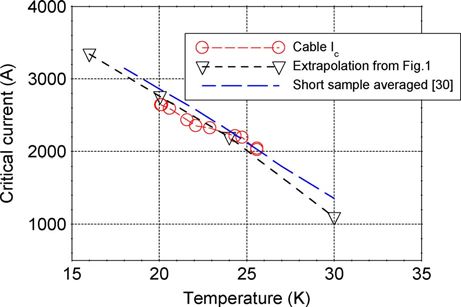
You can also read