LONDON UNDERGROUND COMMUNICATIONS
←
→
Page content transcription
If your browser does not render page correctly, please read the page content below
LONDON UNDERGROUND
COMMUNICATIONS

GROUP 17
Tuan Kamaluddin, T.Amera
Kang, Dong-kyu
Lau, Ka-yin
Xie, Yuchun
Nur, Safa A
Li, Licheng
She, Chenyu
Yuan, Tian

SUPERVISOR

Simons A Evangelou

TABLE OF CONTENTS

ABSTRACT....................................................................................................................................................................1
1. What is Communications System?.........................................................................................................2
2. Leaky Cables........................................................................................................................................................3
3. Cost............................................................................................................................................................................7
4. Comparison..........................................................................................................................................................8
5. Conclusion.............................................................................................................................................................9
ABSTRACT

“Tube commuters hit by ‘rush hour from hell’.” 1

 It was a title in the daily BBC news on the seventh of February 2011. Signal failure has
caused a huge frustration to Londoners, especially those who choose underground
railway or Tube as their main means of transportation.

London Underground (LU) is the oldest underground railway in the world2. With
402km/249miles in length of networks3, it has become the 2nd longest metro in the
world4. On average, 1065 million passengers are carried each year3, showing how
important the Tube is to Londoners.

However, London’s underground railway is lacking communications in terms of cellular
network coverage, unlike its counterparts in Glasgow, Washington DC, Stockholm,
Beijing, Tokyo and Moscow. At present, there is hardly any mobile phone connection
that is the simplest communications technology available on the Tube, let alone the 4th
generation cellular wireless standards5.

Underground communications is useful to Londoners in many ways. Apart from being a
platform for exchange of ideas, some research has shown that 6 out 10 passengers
would like to have mobile phone coverage on the Tube6. The figures are expected to
increase prominently with the upcoming Olympic Games in 2012.

However, further research has shown that a lack of credible proposals from suppliers
has been the main factor of the delay of implementation of underground
communications network by London’s underground authorities7 .

The report should draw readers’ understanding, first on communications system in
general, then the impediments to the existence of underground communications, before
arriving at a solution to this problem.

Given the extensive nature of research that has been performed, and the substantive
nature of the outcome, it is suggested that the report should be submitted as a proposal
paper for TfL to further improve their services.

Hopefully the report will give an insight to all readers about communications
technology in general and how it is useful to our lives!

                                                                                       1
1) What Is Communications system?
Communications system is a system consisting of two ends, transmitter and receiver, in between which
there is a channel. Antenna is a transducer, which is a device that transmits and receives radio waves. It
converts radio waves to electric signal by induction and vice versa.
Nowadays mobile phones use full duplex (i.e. the use of two different frequencies simultaneously) to
transmit data. This means mobile phones can process two frequencies together, one is for transmitting
signal (talking) and one is for receiving signal (listening). The network coverage of mobile phones is
determined by the number of ‘cells’. Cells are small partitions that a city is divided into, whereby each cell
consists of a tower and a small building with radio equipment. Mobile phones operate within cells and can
switch cells as they move around to enable continuous conservation. Same frequency can be reused in
non-adjacent cells.
Typically there are 832 radio frequencies in a city, which can be divided into 395 full duplex voice
channels and 46 control channels. The available number of frequency is increased by 2G technology with
digital transmission methods. The most popular one is GSM, which stands for Global System for Mobile
communications. Voice data is compressed by an analogue-to-digital converter so that less space is taken
and less travel time. GSM uses encryption (for security) and operates in 900MHz or 1800MHz. The main
network providers in the UK, like T-Mobile and Orange, work on the 1800MHz bandwidth while O2 and
Vodafone use 900MHz bandwidth8.
Within the bandwidth, each frequency is identified by Mobile Telephone Switching Office and signal
transmitted from each user is differentiated by a specific code. This specific code or System Identification
Code (SIC) is assigned by the network provider and is searched by control channel when the phone is
switched on. When a phone call is made, the mobile phone sends SID along with registration request to
Mobile Telephone Switching Office (MTSO) which will keep track of your phone location and save it in the
database9. When a phone call is made to you, the MTSO will search your location, before picking an
available frequency pair for your phone to receive the call.
By setting a resonant frequency, only certain bandwidth(s) will be allowed to work with this antenna10.
Radio waves are more reliable because it travels at higher speed and low energy loss through air.
However, it is not penetrable, where signal is absorbed by rocks and soils and partially reflected when it
encounters a surface. So it makes underground communications difficult.
Around
800MHz
Adjacent cell(highlighted) can share same
frequency
Digital
decoder
Cell phone
Digital
encoder
Figure 1 General idea of the whole mobile network above ground.
Cells are like hexagon shape and not overlap with each other; cell
phone uses two frequencies in the bandwidth.
22) Leaky Cables
One solution that we can use is leaky cable. Leaky cable is a normal coaxial cable, with periodic
apertures/slots, for it to emit and receive radio signals. Having this property, it can function as an antenna
where it can distribute radio waves at places where the placement of discrete antenna is not feasible (in
our case, the LU). Typically, there are a few types of leaky cables11, which are determined by the structure
of their outer conductors: braided, axial slotted and periodically slotted coaxial cable12.
Figure 2 General internal structure of a leaky
cable.9
1 Inner Conductor
2 Dielectric
3 Outer Conductor
4 Tape
5 Inner Jacket
6 Outer Jacket
Figure 3 General outer structure of leaky cable (with periodic apertures)13
Inner conductor is usually made of copper wire. There are several types of dielectric that can be used,
depending on the radio wave velocity. Generally it is made of polyethylene with a permittivity about
1.2514, the ratio sufficient for radio wave permeability. The outer conductor, made of copper foil, is the
layer at which the arranged apertures are made.
However, the usage of leaky cable is not as easy as it seems. Since Underground stations are further apart,
one long leaky cable has to be installed. Otherwise, the radio wave connection between the controller
over ground and the mobile phones would fade away as the train moves. Furthermore, there are other
main aspects that we have to look into when we deal with leaky cable which are frequency bands and the
coupling loss.
As mentioned above, every network provider in the UK has their own frequency range for GSM. The
question is 1) How are we going to ensure that, by using this leaky cable, these radio frequencies would
not interfere to each other and from other sources? 2) What is the design of the leaky cable that we have
to look into to overcome this problem?
Another problem is coupling loss. Coupling loss can be defined as the ratio between the power received
by the half-wavelength dipole antenna and the transmitted power in the cable8. How are we going to
guarantee that when the wave is radiated from one medium to the other, there would not be significant
losses in power that would disrupt the connection? These are the things that we are trying to solve and
hopefully would be able to reach to a solid conclusion.
3A) Technicality of Leaky Cable
In this part, periodically-slotted
slotted coaxial cable is analysed theoretically in more detail including equations
and explanations. We will discuss the properties of the slotted coaxial cable, including the basic principle
of frequency bandwidth expansion, coupling char characteristic
acteristic and the field distribution. All these important
parameters will help us understand how exactly the leaky coaxial cable propagates the signal in the
underground telecommunicationss system.
As we have discussed before, the signals transmitted and d distributed
istributed in the leaky coaxial cable are in the
ultra-high
high frequency wave range (from 300MHz - 3GHz) and travel at the speed of light. Unlike the usual
coaxial cable, the leaky coaxial cable implemented in the underground tunnel does not only work as a
normal
rmal cable but also functions as an antenna in the tunnel. Based on the theory of the ray diffraction,
each slot of the radiating cable can work as an antenna spreading the signal out in the tunnel.
Figure 4 Radio waves will behave as the picture
when they
ey pass through the slots.
B) Field distribution
Since each dimension of the slot is relatively smaller than the wavelength of the frequency, the radiation
of the signal can be consider as a magnetic dipole in the free space15 .Therefore the leaky cable will w
behave as long arrays of the magnetic dipoles. Considering radiation in free space, the total electric field
can be expressed as:
∑
(1) where
ßg and k are the wave numbers in the cable;
E0 is the field amplitude of a single slot;
d is the distance between each slot;
θ is the angle of the direction;
By letting k*d*cosθ - ßg *d= 2nЛ (n is any integer), we can find out at which angle we can get the
maximum total electric field and the radiation pattern of different angles. Therefore, by this equation we
can find out where to place our leaky cable to maximise the ssignal.
4C) Frequency bandwidth
In the study of leaky coaxial cable with periodic slots, the two major parameters are frequency bandwidth
and coupling loss. The relationship between frequency bandwidth and the period of the magnetic current
distribution is determined by:
cm c m
− < fIn the UK, both are these are used in the mobile network. However the frequency band of CDMA is very
close to the GSM900. These two systems may interfere with each other particularly between the downlink
of CDMA (870-880MHz) and the upper link of GSM (890-915MHz)17.
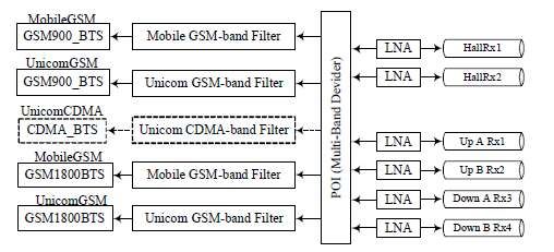
The distribution system consists of leaky cables, transmission lines, Point of Interconnection (POI)
platform and Low Noise Amplifiers (LNA). The POI platform consists of couplers, filters combiners and
splitters. The function of POI is basically to combine multi-band signals and to eliminate the inter-system
interference. For the downlink operation, POI combines multiple signals while for the upper link, it
divides the mixed signals from the leaky cables into signals in different bands.14
In order to ensure that the signals are strong enough to reach mobile phones underground, we need to
amplify the signals. So, amplifiers can be placed before passing them to POI. A variety of signals from
both GSM and CDMA will be filtered into POI platform from base transceiver stations before being sent to
leaky cables. The signals will be first split and then routed to POI platform which are placed in stations,
and tunnels14
Figure 6 Down link of the system
For the upper link, POI platform will divide mixed signals from leaky cables into different frequency band.
The signals are then filtered and sent to the corresponding base transceiver stations. This division
function is convenient to make different systems share a common leaky cable so that the cost of leaky
cables is reduced14.
Figure 7 Upper link of the system
63) COST
According to communications requirements of subway train control system and the characteristic of
leakage wave communications, 2 leaky coaxial cables are required for the communications between left-
going train and right-going train respectively. As leaky coaxial cables are required to be installed on both
sides of the railway, the total length of leakage cable is twice as long as the railway. In the meantime,
receivers and in-train receivers are also required18. However, the main cost of communications lies on the
leakage cables19.
On the other hand, the power consumed in communications is weak current, and the total weak current
consumption only takes up 2% of the total power consumption in the subway system. Therefore the
power consumption cost could be ignored as compared to other parts20.
In choosing the specification of leaky coaxial cables, the construction environmental factor, equipment
parameters and system expansion requirements should all be taken into consideration. The price of
radiated leaky coaxial cables for underground communications system is around US$1,000-US$10,000
per kilometer. Taking other communications charge into consideration, the communications cost for each
meter in tunnel is within US$2,000-US$20,000. Therefore, Piccadilly Line (76 KM) needs at least
US$152,000-US$1,520,00021.
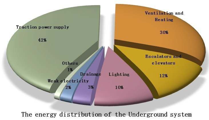
Figure 8 The energy distribution of the Underground system.
74) COMPARISON
Until now we have only evaluated the leaky coaxial cable. However, there are still two other signal
transmission technologies which can be chosen for the project. The wireless sensor network (WSN) for
mobile underground coverage is possible by using either electromagnetic (EM) waves system or magnetic
induction (MI) system. There are pros and cons for each technology.
The traditional terrestrial wireless technology uses EM waves, mainly microwave. But EM wave can no
longer be propagated in air in an underground environment. WSN has three main problems in the
underground situation, namely high path loss, dynamic channel condition and large antenna size. Firstly,
the EM waves will be heavily attenuated by soil, rock and water.
Because space is limited in the underground tube stations, the power available for the equipment will also
be limited, and hence causing transmission range of EM waves to be likely less than 4 metres. Moreover,
the path loss varies dynamically, depending on the soil properties such as water level and soil density,
which will also be dramatically different depending on time and location. This channel condition means
that there will be a difficulty designing a network with reliable connectivity and high power efficiency. In
order to reduce the path loss, the frequency of EM waves can be lowered. But this means larger antennas
are needed for signal transmission, which doesn’t satisfy the small sensor size requirement of a limited
space22.
Instead of the troublesome EM waves system, MI system could be a better form of wireless underground
sensor network (WUSN) because MI communications system can resolve the three major problems faced
by the EM waves system. Basically the transmission and the reception occur by using a coil of wire (see
Figure 9).
Unlike EM waves transmitter, we don’t have to consider the radiation power of MI transmitter. The ratio
of transmitting and receiving power is nearly one, if the resistance of the coil is small. This feature
ensures almost no transmission power lost to the surroundings23. This technology is not affected by the
dynamic channel condition because magnetic permeability of different components of soil is relatively
constant so the channel condition remains the same for most of the time.
The system operates with small-sized coils so there is no need for big antenna, thus saving space. For MI
system, if the transmission distance increases by d, then the magnetic field strength decreases by a factor
of d324. It thus makes MI and EM wave systems hard to be applied in the real world due to their short
transmission ranges, both less than 10 metres25: “the MI system provides larger transmission range
(around 10 m) than that of the EM wave system (around 4 m)”26. Currently there is no technical solution
to improve their transmission range and thus making the leaky coaxial cable the most practical solution.
Figure 9 MI communications channel model27
85) CONCLUSION
Over the past 20 years, the 80% mobile phones ownership has grown to 80%,
demonstrating our continuing reliance on mobile communications. However, the most
important mass transport system to the economy, the LU, is not covered by mobile
networks.
The lack of signal reception in tunnels and underground stations is due to the fact that
radio waves cannot travel through walls – which can be overcame by the use of leaky
cables.
Such approaches have already been implemented in some countries. Therefore, the
delay in solution implementation in this country could be due to a number of factors;
underdeveloped technology is certainly not one of them.
Security can be one such factor. Considering the geological conditions of the channel, as
the oldest railway in the world, the network could be too old and too fragile to support
any installation of new devices. Besides, Londoners are heavily dependent on tube;
therefore any engineering service will disrupt the daily service. Hence, any upgrade to
the system should be thoroughly planned to avoid any further disruptions. Apart from
that, using phone underground may cause signal interference with other equipment,
just like using mobile phone in flight will interfere with the operation of some avionics
instrument installed on aircraft28 .
However, with technological advancement, we are positive that these problems could be
overcame as long as there is adequate funding for further research to improve the
suggested solution and substantial support given by both the authorities and the
general public.
With that, science and technology hopefully will succeed in achieving its ultimate
purpose of making our lives easier!
9REFERENCES
IEEE, transactions on antennas and propagation, vol.
49, no. 12, December 2001
1
http://www.bbc.co.uk/news/uk-england-london-
17 Honglan Yang, Fuyun Ling, “Interference Analysis of
12381011
CDMA Network UsingExisting Integrated Wireless
Distribution Systems in Subways” IEEE 2003.
2 Wolmar 2004, p. 18.
18Guofeng Qian, Hualin Xu. Metro Mobile
3http://www.tfl.gov.uk/corporate/modesoftransport
Communications Design [M] China Railway Press,
/londonunderground/1608.aspx 1994
4The New York Times. 19Peregrinus P. Leakage the feedback line and
http://www.nytimes.com/2010/04/30/world/asia/ underound wireless communication [M] Chunnian
30shanghai.html?_r=1. Retrieved 31 December 2010. Wang, Yaosen Dai, Huaizhen Gao. Beijing People's
Posts and Telecommunications Press,1982
5http://www.itu.int/ITU-
R/index.asp?category=information&rlink=imt- 20 Long Tan. URBAN MASS TRANSIT, 2010
advanced&lang=en
20http://uk.alibaba.com/trading-
6 http://conversation.which.co.uk/transport- search?CatId=0&Country=&SearchText=leaky+coaxia
travel/do-you-want-mobile-coverage-on-london- l+cable&IndexArea=product_en
underground/
22Pg1, ‘1.Introduction’ section, 2nd paragraph,
7http://www.cellularnews.com/story/36527.php
‘Magnetic Induction Communication for Wireless
8 Underground Sensor Networks’ by Zhi Sun and Ian F.
http://www.ukstudentlife.com/Life/Telephone/Mobile.
htm Akyildiz.
9Roger L. Freeman (2004). Telecommunication system
23Pg4, ‘3.MI channel characteristic’, ‘B.Path loss’, 2nd
engineering. John Wiley and Sons. paragraph, Magnetic Induction Communication for
Wireless Underground Sensor Networks’ by Zhi Sun
10Antenna Theory (3rd edition), by C. Balanis, Wiley, and Ian F. Akyildiz.
2005, ISBN 0-471-66782-X;
24Pg1, ‘1.Introduction’ section, 4th paragraph,
11Jun Hong Wang, “ Research on the Radiation ‘Magnetic Induction Communication for Wireless
Characteristics of Patched Leaky Coaxial Cable by Underground Sensor Networks’ by Zhi Sun and Ian F.
FDTD Method and Mode Expansion Method “ IEEE Akyildiz.
12Jun Hong Wang, “ Research on the Radiation 25Pg9, ‘5.Conclusion’ section, 2nd bullet point,
Characteristics of Patched Leaky Coaxial Cable by ‘Magnetic Induction Communication for Wireless
FDTD Method and Mode Expansion Method “ IEEE Underground Sensor Networks’ by Zhi Sun and Ian F.
Akyildiz.
13http://www.solwise.co.uk/downloads/files/leaky-
feeder-cable-introduction.pdf 26Pg6, ‘3.MI channel characteristic’, ‘C.Numerical
Analysis’, ‘3) Bandwidth’, 2nd paragraph, Magnetic
14Jun Hong Wang, Kenneth K. Mei, “Transactions On Induction Communication for Wireless Underground
Antennas And Propagation”, Vol. 49, No. 12, Sensor Networks’ by Zhi Sun and Ian F. Akyildiz.
December 2001 IEEE
27Pg2, ‘Magnetic Induction Communication for
15M. LiCnard, Ph. Mariage, J. Vandamme and P. Wireless Underground Sensor Networks’ by Zhi Sun
Degauque, “Radiowave retransmission in confined and Ian F. Akyildiz.
areas using radiating cable: Theoretical and
experimental study,” IEEE, 1994 28http://www.boeing.com/commercial/aeromagazin
e/aero_10/interfere_textonly.html
16Jun Hong Wang and Kenneth K.Mei, “Theory and
analysis of leaky coaxial cables with periodic slots,”
10You can also read